DAITEM SH630AX User manual


2
The command and information keypad can be used to operate an intrusion protection system from outside or inside the
home.
The keypad commands can be accessed:
• using the master code,
• using the 8 user codes.
Each command is confirmed with an audible signal and a visual signal (LED) issued by the keypad. The keypad also
indicates the system status and any faults or open doors or windows.
The keypad is protected against:
• opening,
• removal,
• attempts to discover the access code.
1. Introduction
8 command buttons
can be personalised
Two-colour LED
Buttons
for access codes
and programming
Arm
If the level of lighting is low or a button is pressed, the buttons and keypad are back-lit for 10 s.
The back-lighting period is repeated for 10 s when the last key is pressed.
Disarm
Partial 1
Partial 2
Arm Presence
System status query
Not allocated
Not allocated
1.1 LED indications
LED LED status Meaning
Red steady button pressed correctly
1 flash every 5 s keypad in test mode
2 flashes every 10 s keypad in installation mode
3 quick flashes handling or programming error, access code invalid
Green steady for 2 s correct programming
steady for 10 s access code valid (the 10 s period is repeated after each command)
IMP RTANT
• Some functions are only available with control panel versions 2.0.0 or later (enter on the control
panel keypad to check the version).
• perational differences in relation to former ranges are described in the compatibility booklet available in the Daitem Installers
section at www.daitem.co.uk.

3
1.2 Information feedback indications
IMP RTANT: only the commands sent from the keypad result in the following audible and visual responses. rders issued by
another remote control unit do not lead to a keypad response.
Command sent to: LED status and colour Buzzer Meaning
An alarm control panel lights up steady GREEN
for 1.5 s
Long beep Total or group DISARMING
flashes GREEN 3 times 3 short beeps Total or group DISARMING
with alarm memory
lights up steady RED
for 1.5 s
Long beep Total, partial or group
ARMING
lights up steady RED
for 1.5 s
3 short beeps Total, partial or group
ARMING with a fault
or an open exit
flashes RED 3 times 3 short beeps ARMING blocked (1)
A command receiver
or remote-controlled socket
lights up steady GREEN
for 1.5 s
/ Transmission of home control
command (light, relay, etc.)
(1) ARMING blocked means that the intrusion system has been unable to arm owing to a system fault.
The user must check the control panel for more information.
2.1 Tooling required
6 mm
2.5 mm
PH.1
2. Pre aration
IMP RTANT: the fixing screws and plugs are not provided.

4
1. Unclip the front panel
from the bottom.
2. Remove the front panel.
3. Loosen the 2 screws. 4. Remove the electronic part
from the base.
5. Remove the pre-cut part of the sticker and
stick it to the guarantee certificate inside
the user manual supplied with the control
panel. If you are adding to an existing
system, use the guarantee certificate
supplied with this product.
6. Connect the lithium power pack to its support.
7. Push the lithium power pack lock downwards.
Philips PH.1
Coller sur certif
SH630AX
A1235A04824
SH630AX
A1235A04824
The keypad will issue a long beep and
the LED will light up RED for 2 s.
“Bip”
2.2 Power supply

5
3. Changing the o erating mode
IMP RTANT
• When the keypad is powered it is in user mode.
• The keypad must be in installation mode for recognition programming and parameter-setting.
4. Recognition rogramming
IMP RTANT: the product does not need to be placed next to the control panel for recognition programming. In fact, it is
advisable to move it at least 2 metres away from the control panel.
Recognition programming allows the control panel to recognise the keypad.
1. Make sure the control panel is in
installation mode (see Control panel
installation manual) with its front cover
removed.
3. Perform the following recognition programming procedure:
IMP RTANT: the control panel issues 3 short beeps to indicate a programming error. If this happens, the recognition
programming procedure should be performed again from the start.
Press *then #on the
control panel keypad
Press and hold “ ff” until
the control panel responds
The control panel issues a voice
message to confirm keypad recognition
The keypad issues a long beep
to confirm recognition.
)))))
10 s max.
“bip”
then
The mode can be changed by entering the factory master code “0000” then the factory installer code “1111” as shown
below:
IMP RTANT
• For security reasons, the keypad automatically switches back to user mode after 4 hours without a command being issued.
• If 5 wrong codes are entered in less than 5 minutes the keypad will be blocked for 5 minutes.
• If the keypad:
- is used without a control panel (e.g. command from external receiver),
- is not or no longer recognised by a control panel,
the operating mode cannot be changed if the tamper pin on the back is pressed in.
INSTALLATION
MODE
TEST MODE
USER MODE
installer code
master code
master code
installer code
installer code
Operating mode
on power-up
1 flash
every 5 s
2 flashes
every 10 s
2. Switch the keypad to installation mode by entering:
then
master code
(factory: 0000)
installer code
(factory: 1111)
“bip”
“bip”
“bip, remote ontrol unit X”

6
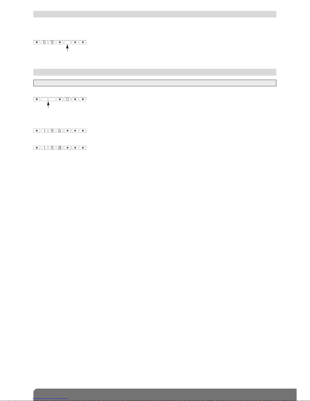
5.4 Modifying the installer code
The Installer code is for use by the installer.
It is used to access all keypad installation, programming and maintenance operations in INSTALLATION mode.
To ensure system confidentiality, the installer code must be changed. To do this, enter:
Example: to replace the factory installer code “1111” with the new code “6789”, enter:
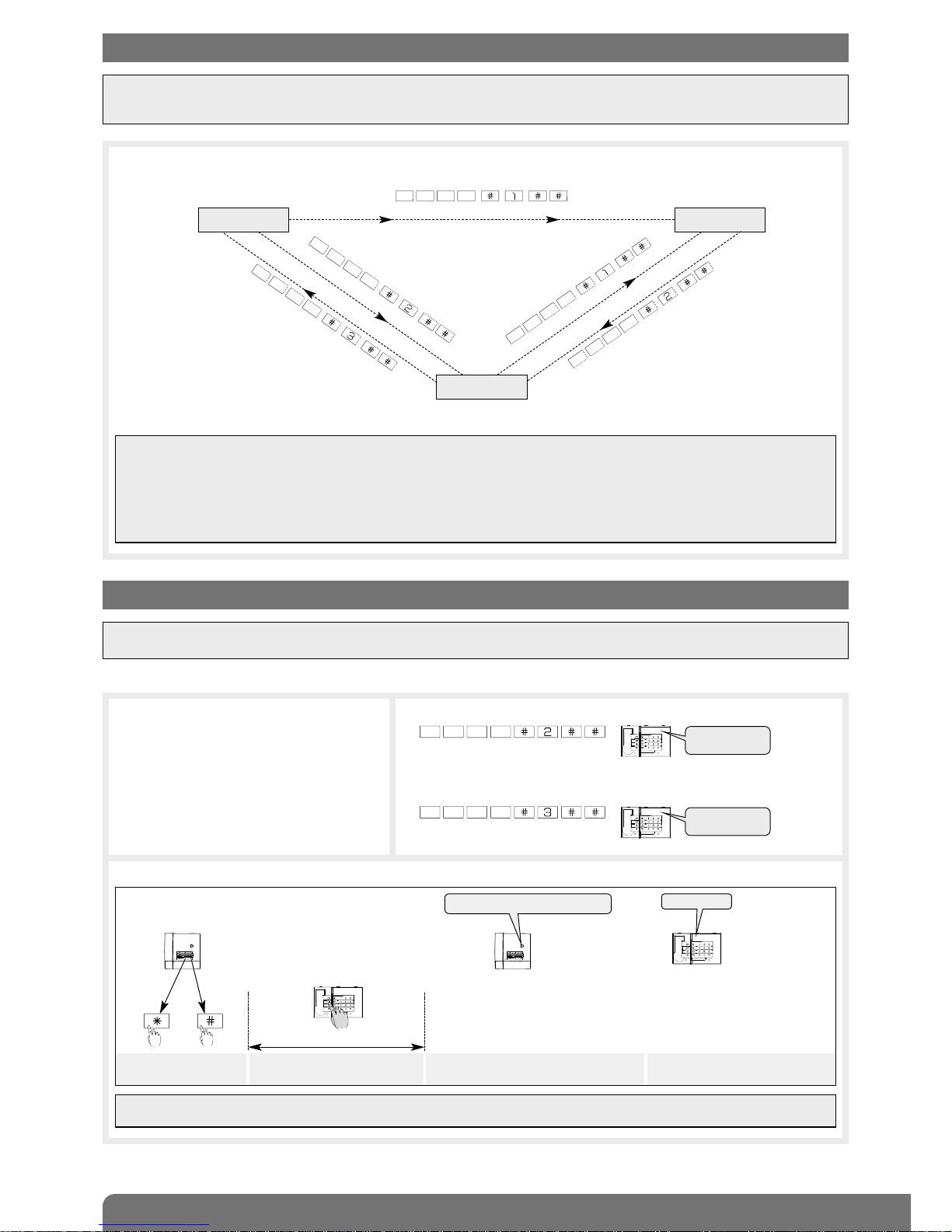
5.1 Managing beeps
0: beeps disabled
1: beeps enabled
The beeps issued by the keypad can be deactivated. Enter:
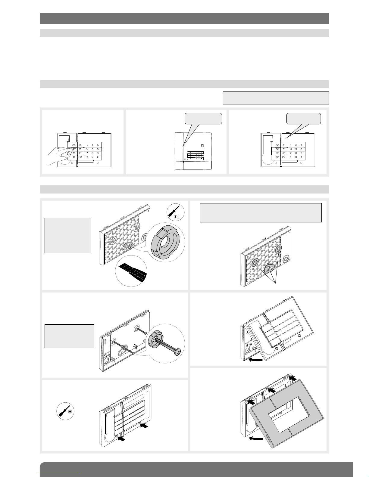
IMP RTANT:
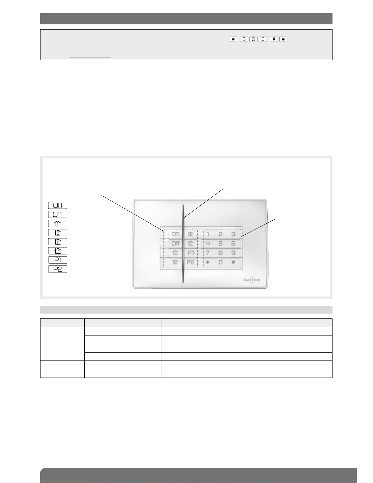
• Before setting any parameters, the keypad must first be in installation mode (see chapter 3. Changing the operating mode).
• A long beep is issued and the LED lights up green for 2 s to indicate correct programming. If an error is made, the red LED
flashes 3 times and the keypad issues 3 short beeps.
5. Parameter-setting
IMP RTANT: the number of access code digits can only be modified when all the access codes correspond to the factory
values. To do this, put the keypad in installation mode and enter: .
IMP RTANT: the 3 error beeps cannot be deactivated
even if this function has been disabled.
5.2 Number of access code digits
Before modifying the keypad access codes, the number of access code digits must be determined (4 digits in the factory
code).
If you extend the number of digits this will apply to all the following:
• the master code,
• the installer code,
• the 8 user codes.
To modify the number of digits, enter:
Example: to extend the access codes to 6 digits, enter:
number of digits (4 to 6)
IMP RTANT
• Forbidden access codes: 0000, 1111, 2222, 3333.
• The master code can be modified in the three operating modes: installation mode, test mode or user mode.
5.3 Modifying the master code
The master code is for use by the main user and enables:
• use of all keypad functions (all commands),
• access to TEST mode and USER mode,
• control (authorisation or non-authorisation) of User codes.
To ensure system confidentiality, the master code must be changed. To do this, enter:
Example: to replace the factory master code “0000” with the new code “1234”, enter:
old code new code new code

7
IMP RTANT: there are no factory programmed user codes.
5.5 Managing user codes
The user codes are for secondary and occasional users (service staff, employees, etc.).
They allow for limited and temporary use of the keypad:
• restricted access to specific commands or specific groups can be programmed for each user code,
• each user code can be enabled or disabled at any time.
The keypad has 8 user codes.
To programme or modify a user code, enter:
Example: after entering the master code (1234), programme user number 1 (1213) by entering:
5.5.1 Disabling and enabling a user code
User codes can be disabled or enabled in the 3 operating modes.
A programmed user code is automatically enabled.
To disable or enable a user code, enter:
Example: to disable user code 1, enter:
master code user code1 to 8 (choice
of user number)
user code
master code 0: disabled
1: enabled
1 to 8 (choice
of user number)
5.5.2 Restricted access to commands
User codes can have separate limited access to:
• specific keypad command buttons,
• specific groups.
Only selected commands or groups can be accessed when the user code is entered.
• To restrict a user code to (a) specific command button(s), enter:
Example: to restrict user code 1 (1213) to the Partial 1 command, enter:
In this case, only the Partial 1 button can be accessed via user code 1.
...
master code user code1 to 8 (choice
of user number)
user code command
button(s)
• To restrict a user code to (a) specific group(s), enter:
Example: to restrict user code 1 (1213) to Group 1 and Group 2, enter:
In this case, user code 1 can only disarm and arm Group 1 and Group 2.
...
master code user code1 to 8 (choice
of user number)
user code groups 1 to 8
5.5.3 Restricted access to both a command button and a group
Example: to restrict user code 1 (1213) to Group 1 Arm/Disarm and the Partial 1 button, enter:
In this case, user code 1 can only disarm or arm Group 1
and operate the Partial 1 button. Group 1 “Partial one”
command button

8
5.6 Personalising a command button
IMP RTANT
• In installation mode, the keypad commands can be
accessed directly.
• In User mode all Arm or Disarm commands as well as the
System Status command can only be accessed by using a
User code.
The 8 keypad command keys can be personalised to adapt keypad commands to user needs (see table below)..
Furthermore, this personalisation allows the user to choose between direct or code-based access to keypad commands.
To personalise a command key, enter:
5.7 Personalising a command button for arming or disarming groups 1 to 8
ey to be
personalised
Command number
(see table below)
Type of access:
0: direct access
1: code-based access
Example: to personalise the button for an “Alert” command accessed via a code, enter:
• To personalise a button to arm groups 1 to 8, enter:
...
Example: personalise the button to arm group 5 and 6:
button to be
personalised
groups 1 to 8 depending
on the type of control panel
• To personalise a button to disarm groups 1 to 8, enter:
...
Example: personalise the button to disarm group 7 and 8:
button to be
personalised
groups 1 to 8 depending
on the type of control panel
IMP RTANT: all disarm and arm commands can only be accessed via a code.
Command description Command n°
Disarm (1) 21
Alert 22
Arm (1) 23
Silent alarm 24
Partially arm 1 (1) 25
Partially arm 2 (1) 27
Fire alarm 32
Arm presence 33
Silent command 36
Stop indications (1) (2) 37
Chime 38
Audible signal 42
No command 44
Light pulse 50
Off light 52
Command description Command n°
On light 54
Light toggle switch 56
Light timer 58
Relay 1 pulse 60
Off relay 1 62
On relay 1 64
Relay 1 toggle switch 66
Relay 1 timer 68
Relay 2 pulse 70
Off relay 2 72
On relay 2 74
Relay 2 toggle switch 76
Relay 2 timer 78
Relay 3 pulse 80
Off relay 3 82
Command description Command n°
On relay 3 84
Relay 3 toggle switch 86
Relay 3 timer 88
Relay 4 pulse 90
Off relay 4 92
On relay 4 94
Relay 4 toggle switch 96
Relay 4 timer 98
Off relay control panel 1 112
On relay control panel 1 114
Off relay control panel 2 122
On relay control panel 2 124
System status (1) 129
(1) Command with code access only.
(2) Used to stop indications concerning a technical alarm, an alert or a tamper alarm without changing the system status.
Important: telephone transmissions are not interrupted.

9
5.8 Managing back-lighting
If the level of lighting is low or a button is pressed, the buttons and keypad are back-lit for 10 s.
The back-lighting period is repeated for 10 s when the last button is pressed.
To activate or deactivate back-lighting, enter:
0: disabled
1: enabled (factory)
5.9 Deleting parameters
To delete a parameter, enter:
To delete all the access codes, enter:
To return to the factory setting, enter:
parameter number
IMP RTANT: parameters can only be deleted if the keypad is in installation mode.

10
6.1 Choosing the best place
6.3 Fixing the keypad in place
6. Installing the device
1. Remove the fixing washer
from the back of the keypad.
2,5
2.
IMP RTANT: once
the washer has
been removed,
remove any burrs
from the keypad
and washer.
IMP RTANT: if the keypad is installed outside,
position the pieces of foam provided around the
fixing slots.
Pieces of foam
3. Position the base on the wall in order to determine the 3
fixing points. Insert the washer removed during step 1
and fix it in place using suitable
plugs and screws.
5. Tighten the 2 screws.
6. ¿Hook the top of the front
face on the 3 clips.
¡Clip the front face on.
4. Position the electronic part
on the base.
Philips PH.1
¿
¡
IMP RTANT: use
Ø 4 mm max screws
with Ø 8 mm max
heads.
6.2 Testing the radio range
Before fixing the keypad in place, position it in the desired location and test
the radio range. If it is good, fix the keypad in place, otherwise move it.
1. Press the “ ff” key. 2. The control panel
issues the
message:
3. The keypad issues
a long beep to
confirm.
“beeep”
“bip, off, remote
ontrol unit X”
The keypad can be installed:
• inside,
• outside the premises in a sheltered location,
• making sure that there is a distance of at least 2 metres between each product, except between two detectors.
The keypad cannot be installed: directly on a metal surface or close to sources of interference (e.g. electricity meter).
N TE: the keypad will have to be recognised
by the Control panel first , see section 4.0.

11
To change the battery:
1. Switch the system to installation mode
using the keypad to enter:
then
master code
installer code
IMP RTANT: if the battery fails, the red LED and back-lighting no longer come on when a key is pressed.
8.2 Changing the battery
2. Remove the keypad front panel.
“bip”
“bip”
8.1 Fault indications
The control panel supervises and identifies the keypad.
It monitors the state of:
• the battery,
• the radio link,
• the tamper contact.
If a fault has been memorised, the control panel issues a voice message indicating the fault following a system command
(see § Fault indications in the control panel installation manual).
The keypad also issues an audible and visual signal of faults following a command issued from the keypad.
8. Maintenance
Once the radio range test has been performed:
1. Switch the keypad to user mode by entering:
7. Switching to user mode
IMP RTANT: putting the keypad in user mode automatically puts the control panel in user mode. Consequently, the keypad
should only be switched to user mode when all the parameters have been set on the different system products (keypads,
detectors, etc.).
installer code
2. Put the front cover back on the control panel.
• Example: following a system status query command issued from the keypad, the keypad battery fault is indicated:
IMP RTANT: a keypad battery fault is also indicated by
the red LED not being lit and by the absence of back-
lighting when a button is pressed.
LED colour
and status
Buzzer
Lights up steady
RED for 1.5 s
3 short
beeps
“bip”“bip, Off”
“Bip, system status, armed
partial 2, bip, on 12/03/2012
at 12 PM, fault, voltage,
remote ontrol unit 1”

12
IMP RTANT: before connecting
the new lithium power pack,
press on a keypad button to
delete the battery fault.
The keypad battery fault is
automatically deleted from the
control panel 10 min after the
battery has been changed.
IMP RTANT
• The lithium battery pack must be replaced with the same type of pack with the same technical characteristics,
i.e. 2 x (3 V – 2.4 Ah).
• We advise you to use the DAITEM RXU02X battery available in the catalogue in order to guarantee individual safety
and equipment reliability.
• Dispose of the waste lithium power pack in an appropriate recycling bin.
Li
7. Position the electronic part
on the base.
8. Tighten the 2 screws. 9. Put the front panel back
on the keypad.
Philips PH.1
10. Switch the system to user mode using the keypad to enter:
master code
IMP RTANT: the keypad parameters are saved when the lithium pack is changed.
“bip”
¿
¡
5. Insert a new lithium power pack.
6. Push the lithium power pack lock downwards. The keypad issues a long beep
and the LED lights up red for 2 s.
“Bip”
3. Loosen the 2 screws and remove the electronic
part from the base.
4. Push the lithium power pack lock upwards
and then remove it.
Philips PH.1

13
9. Summary of arameters
Parameter description Parameter-setting sequence Factory
parameters Possible values Page
Number of access code
digits
* 69 * ? ** 4 digits code with 4, 5 or 6 digits 6
Master code
programming
MMMM * 50 * ? ? ? ? * ? ? ? ? ** 0 0 0 0 code with 4, 5 or 6 digits 6
Installer code
programming
I I I I * 51 * ? ? ? ? * ? ? ? ? ** 1 1 1 1 code with 4, 5 or 6 digits 6
Command button
personalisation
* 58 * T * n° * a ess **
access to
commands
via code
T: key to be personalised
n°: command n°
access:
0 = direct access
1 = access via code
8
User code programming MMMM * 20 X * UUUU * UUUU ** none X: 1 to 8 7
Access restricted to
specific command key(s)
MMMM * 20 X * UUUU * UUUU * T ** X: 1 to 8
T: personalised command key(s)
7
Access restricted
to specific groups
MMMM * 20 X * UUUU * UUUU * G ** X: 1 to 8
G: groups 1 to 8
7
User code
enabled/disabled
MMMM * 20 X * Y ** user code not
programmed
X: 1 to 8
Y: 0 = disabled
1 = enabled
7
Management of beeps * 12 * X ** enabled X = 0: beeps disabled
1: beeps enabled
6
Activation of back-lighting * 59 * X ** enabled X = 0: disabled
1: enabled
9
Deletion of all access
codes
* 196 *** 9
Deletion of one parameter * parameter n° * 0 ** 9
MMMM = master code I I I I = installer code UUUU = user code

14
Technical data SH630AX command keypad
Command keys 8 programmable keys
Back-lighting according to lighting level and when a key is pressed
Access codes • 1 installer code
• 1 master code
• 8 user codes
Indications audible and visual indications of system status, alarms, exits and faults
LED two-colour LED to support use and programming
Environment Indoor/outdoor in a sheltered location
Power supply 2 x (3 V – 2.4 Ah) lithium battery pack
Battery life 5 years in normal conditions of use
Average humidity rate 5% to 75% without condensation at 25°C possibly varying between 85% & 95%
for 30 days over the course of the year
Radio links TwinBand®400/800 MHz
Environment indoor/outdoor in a sheltered location
Operating temperature -25°C to +55°C
Tamper protection • against opening
• against removal
• against access code search
Degrees of mechanical protection IP 53 / I 07
Dimensions H x W x D 115 x 176 x 24 mm
Weight 340 g (with battery)
Designed to comply with the requirements of EN50131-3 grade 2 class III
10. Technical data
DECLARATI N F C NF RMITY
Manufacturer: Hager Security SAS
Address: F-38926 Crolles Cedex - France
Product type: Command keypad
Trade mark: Daitem
We declare under our sole responsibility that the product to which this declaration
relates is compliant with the essential requirements of the following directives:
• R&TTE directive: 99/5/EEC
• Low voltage directive: 2006/95/EC
• R HS directive: 2002/95/EC
in compliance with the following harmonised European standards:
This product can be used in all EU, EEA Countries and Switzerland.
Crolles, 02.01.2013 Signature:
Patrick Bernard
Research & Development Manager
Product reference SH630AX
EN 300 220-2 V2.3.1 X
EN 300 330-2 V1.3.1
EN 50130-4 (2001) X
EN 55022 & 55024 (2002)
EN 60950 (2006) X
EN 301 489-1 V1.8.1 X
Non-binding document, subject to modification without notice.
13
GB
To obtain advi e when installing your system or before returning equipment, please onta t the Daitem
te hni al support team (see telephone number at the ba k of the alarm system installation manual)
or he k the web site at:
www.daitem.co.uk
A team of qualified te hni ians will advise you what to do.
Recommendations
The user must not attempt to access the device’s internal parts, except areas described in this manual. If the user does
access these parts, the product guarantee will be considered null and void and DAITEM shall not be held responsible for any
problems. Touching the device’s internal parts and/or electronic components can damage the product. Furthermore, the
device is designed in such a way that these parts and components do not need to be accessed for operation or
maintenance purposes.

15

805093/A - 02.2013
Table of contents