Dake SLTC93 Quick start guide

INFORMAZIONI COMMERCIALI PER I CONSUMATORI
COMMERCIAL INFORMATION FOR THE CONSUMER
INFORMATIONS COMMERCIALES POUR LE CLIENT
INFORMACIONES COMERCIALES PARA EL CLIENTE
HANDELSINFORMATIONEN FÜR DEN KUNDEN
COMMERCIËLE INFORMATIES VOOR DE KLANT
INFORMAZIONI TECNICHE
TECHNICAL INFORMATION
INFORMATION TECHNIQUES
INFORMACIONES TÉCNICAS
TECHNISCHE INFORMATIONEN
TECHNISCHE INFORMATIES
ISTRUZIONI PER L’INSTALLAZIONE,L’USO E LA MANUTENZIONE
IT
INSTALLATION, USE AND MAINTENANCE OF HOOD
GB
INSTRUCTIONS POUR L’INSTALLATION, L’EMPLOI ET L’ENTRETIEN
DE LA HOTTE
F
INSTRUCCIONES PARA LA INSTALACIÓN, USO Y MANTENIMIENTO
DEL PRODUCTO
ES
BEDIENUNGSANLEITUNG MIT MONTAGEANWEISUNGEN FÜR
DE
INSTRUCTIES VOOR DE INSTALLATIE, HET GEBRUIK EN HET
ONDERHOUD VAN HET PRODUCT
NL
SLTC93 - SLTC94 - SLTC95 - SL96 - SLTC97 - SLTC103

2

1 2
3 4
5 6
3

7 8
9 10
11 12
4

13 14
15 16
17 18
5

19
6

INDICE
Avvertenze
Versioni d’uso
Installazione
Funzionamento
Temporizzazioni
Manutenzione
IT
7

sull’uso dell’apparecchio in
modo sicuro e comprendono
pericoli coinvolti.
- I bambini non devono giocare
con l’apparecchio.
- la pulizia e la manutenzione
non devono essere eseguite da
bambi ni senza supervisione.
- Se il cavo di alimentazione è
danneggiato, esso deve essere
sosti tuito da un cavo o da un
assemblaggio speciale, disponi-
bili presso il costruttore o il suo
servizio assistenza tecnica.
- Il locale deve disporre di ade-
guata ventilazione quando si
utilizza la cappa da cucina con-
temporaneamente con altri ap-
parecchi che impiegano gas o
altri combustibili (non si applica
agli apparecchi che si limitano a
scaricare nuovamente l’aria nel
locale);
- Esiste la possibilità di incendio
qualora le operazioni di pulizia
non vengano effettuate secondo
quanto indicato nelle istruzioni;
- Non preparare alimenti ambé
sotto la cappa da cucina.
ATTENZIONE: Le parti accessi-
bili possono scottare se utilizza-
te in concomitanza con gli appa-
recchi di cottura.
AVVERTENZE
L’uscita aria dell’apparecchio,
non deve essere collegata ad
un condotto usato per lo sca-
rico di altri fumi quali impianti
di riscaldamento, scaldabagni,
ecc..
Per l’emissione all’esterno
dell’aria rispettare le norme vi-
genti.
L’alimentazione per il motore
della centralina avviene tramite
la cappa posta in cucina.
Prima del collegamento elettri-
co assicurarsi che i valori di ten-
sione dell’abitazione corrispon-
dano con quelli delle traghette
dati elettrici dell’apparecchio.
Prima di procedere a qualsiasi
tipo di operazione di pulizia o
manutenzione assicurarsi che
l’apparecchio sia scollegato
dalla rete elettrica.
Una buona manutenzione ga-
rantisce un buon funzionamen-
to ed un buon rendimento nel
tempo.
Tutti i modelli sono in classe I
pertanto necessitano di colle-
gamento a terra.
- Questo apparecchio può es-
sere utilizzato da bambini di
età pari o superiore a 8 anni e
da persone con ridotte capaci-
tà siche, sensoriali o mentali
o mancanza di esperienza e co-
noscenza se sono stati sottopo-
sti a supervisione o istruzione 8

VERSIONI D’USO
L’apparecchio può essere utilizzato sia in versio-
ne ltrante che in versione aspirante.
Nella versione ltrante (Fig. 1) l’aria ed i vapori
convogliati dall’apparecchio, vengono depurati
da un ltro antigrasso, da un ltro al carbone e
rimessi in circolazione nell’ambiente.
Nella versione aspirante (Fig. 2) i vapori vengo-
no convogliati direttamente all’esterno, tramite
un condotto di evacuazione. L’utilizzo del ltro al
carbone non è necessario.
INSTALLAZIONE
La ditta produttrice non risponde per danni
causati durante la movimentazione e l’instal-
lazione del prodotto.
Prima di procedere all’installazione leggere
attentamente tutte le istruzioni di seguito ri-
portate.
Vericare che tutti i componenti non siano dan-
neggiati, in caso contrario contattare il rivenditore
e non proseguire con l’installazione.
- Utilizzare un tubo evacuazione aria che abbia
la lunghezza minima possibile, limitato numero di
curve, materiale approvato normativamente.
- Evitare cambiamenti drastici di sezione (diame-
tro costante consigliato Ø 150 mm o pari super-
cie).
- Per il mancato rispetto delle precedenti istruzio-
ni la ditta fornitrice non risponderà per problemi di
portata o di rumorosità e nessuna garanzia sarà
prestata.
Tutti i prodotti sono stati progettati con la possi-
bilità di orientare l’uscita aria nel lato posteriore
del prodotto; nel caso si intenda utilizzare questa
funzione occorre rimuovere le n° 10 viti del sup-
porto gruppo aspirazione (dis. 3 ), quindi estrarre
il gruppo aspirazione e ruotarlo in modo da orien-
tare il boccaglio uscita aria verso il lato posteriore
del prodotto (dis. 4), successivamente ricollocare
il gruppo aspirazione nella propria sede e ripristi-
nare le viti rimosse in precedenza.
Utilizzando l’apposita maschera di foratura (dis.
5A), effettuare i fori per l’installazione delle staffe
a muro.
Il punto più basso posteriore del prodotto deve
essere posizionato alla seguente distanza, ri-
spetto al piano cottura:
SLTC93 distanza dal piano cottura minimo:
495mm
SLTC94 - SLTC103 distanza dal piano cottura
minimo: 500mm
SLTC95 distanza dal piano cottura minimo:
450mm
SL96 distanza dal piano cottura minimo:
600mm
9

SLTC97 distanza dal piano cottura minimo:
650mm
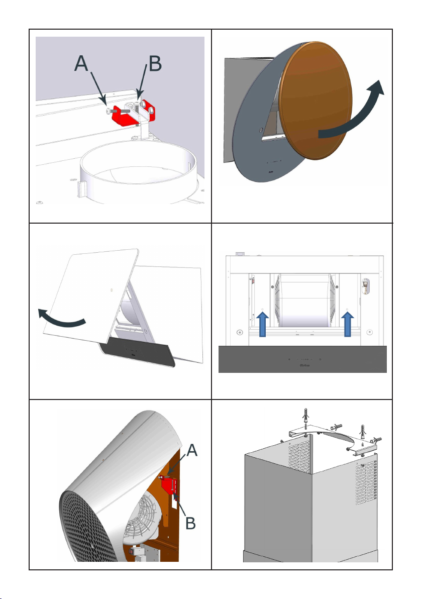
Fissare le staffe a muro, alla parete utilizzando i
tasselli e le viti in dotazione. (FIG.6 A).
Agganciare il corpo aspirante alle staffe a muro
precedentemente ssate. (FIG. 6).
SLTC93 - SLTC94 - SLTC95 - SLTC97 - SLTC103
Avvitare le due viti nella staffa a muro (g. 7A)
necessarie a far aderire il prodotto alla parete,
successivamente vericare che la cappa sia per-
fettamente in piano, in caso contrario agire sulle
viti indicate in g. 7B, avvitando la vite per alzare
il lato corrispondente oppure svitandola in caso
sia necessario ridurre l’altezza.
Effettuare il collegamento elettrico mediante l’ap-
posito cavo di alimentazione.
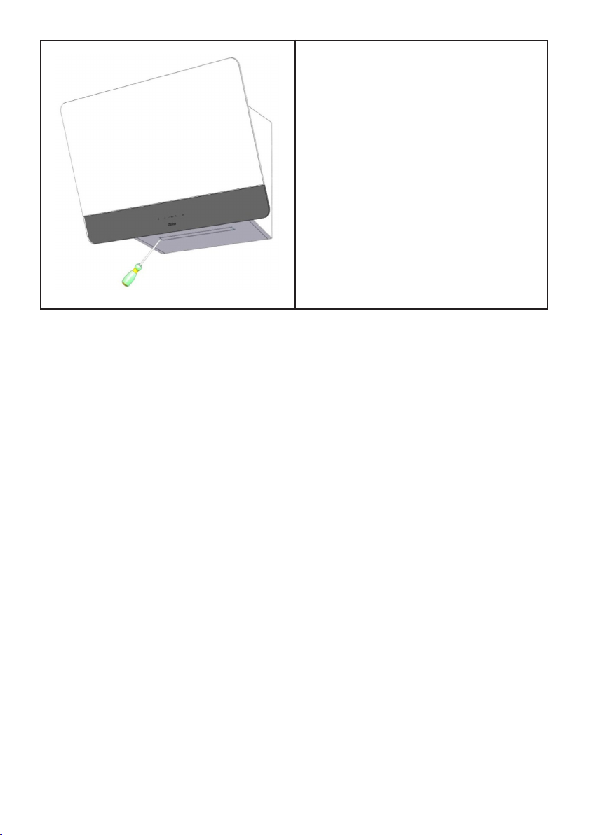
Solo per i prodotti SLTC93 e SLTC94, aprire il
pannello frontale ruotando la parte inferiore verso
l’alto come indica il (dis. 8 e g. 9).
Rimuovere il ltro antigrasso al ne di avere ac-
cesso alla parte interna del prodotto. Il ltro viene
rimosso come indicato nel capitolo manutenzio-
ne.
Bloccare denitivamente il prodotto alla parete
mediante le viti in dotazione come da (dis. 10).
Ripristinare il ltro antigrasso e richiudere il pan-
nello frontale.
SL96
Rimuovere il ltro antigrasso come indicato nel
capitolo manutenzione.
Avvitare le due viti nella staffa a muro (g. 11 A
) necessarie a far aderire il prodotto alla parete,
successivamente vericare che la cappa sia per-
fettamente in piano, in caso contrario agire sulle
viti indicate in g. 11 B, avvitando la vite per al-
zare il lato corrispondente oppure svitandola in
caso sia necessario ridurre l’altezza.
Effettuare il collegamento elettrico mediante l’ap-
posito cavo di alimentazione.
Bloccare denitivamente il prodotto alla parete
mediante le viti in dotazione come da (dis. 10).
Ripristinare il ltro antigrasso, vedi capitolo ma-
nutenzione.
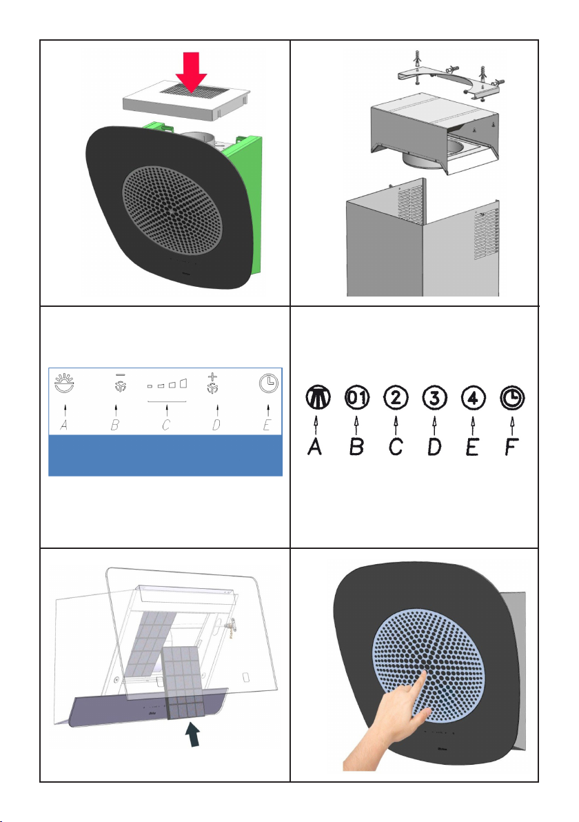
Versione aspirante (uscita superiore).
Mediante i tasselli e le viti in dotazione ssare
alla parete e/o al softto la staffa supporto tubo
(dis. 12), in posizione centrale rispetto alla cappa.
Collegare la angia uscita aria del motore al foro
di evacuazione tramite un tubo adatto.
Posizionare i due tubi decorativi sopra al corpo
aspirante; sollevare il tubo interno afnché arrivi
alla staffa; quindi ssarlo utilizzando n° 2 viti au-
tolettanti in dotazione.
La versione aspirante con uscita aria superio-
re non è realizzabile con il prodotto SL96.
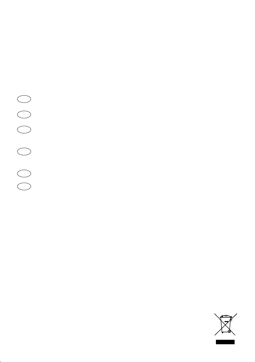
Versione aspirante (uscita posteriore).
E’ necessario ruotare il motore di aspirazione,
come indicato nel capitolo installazione e nelle
gure 3 e 4, al ne di orientare l’uscita aria del
motore verso il lato posteriore del prodotto.
Installare la griglia uscita aria in corrispondenza
della relativa sede sopra la cappa (g. 13). I tubi
decorativi in acciaio non sono necessari.
Nel prodotto SLTC97 occorre sempre instal-
lare i tubi decorativi in acciaio anche se viene
usata l’uscita aria posteriore.
Versione ltrante.
Installare la griglia uscita aria in corrispondenza
della relativa sede sopra la cappa (g. 13). I tubi
decorativi in acciaio non sono necessari.
Nella versione ltrante è necessario installare an-
che il ltro carbone, come indicato nel capitolo
manutenzione a seconda del modello.
Nel prodotto SLTC97 occorre sempre installa-
re i tubi decorativi in acciaio anche in versio-
ne ltrante.
10

E’ disponibile come accessorio (non per il pro-
dotto SL96), un deettore aria che permette di
convogliare l’aria in uscita dal motore direttamen-
te verso le griglie dei tubi decorativi in acciaio
(g. 14), il deettore aria deve essere collegato
all’uscita aria del motore di aspirazione mediante
un tubo adatto, non fornito in dotazione.
FUNZIONAMENTO
SLTC Glass (dis. 15)
A : ON/OFF luci
B : riduzione velocità / OFF motore
C : indicatori velocità
D : ON motore/aumento velocità
E : temporizzatore 10 min.
La pulsantiera Touch control su vetro per mette di
impostare la funzione desiderata sorando il rela-
tivo simbolo. Se il prodotto SLTC rimane privo di
alimentazione elettri ca, al momento del ripristino
delle funzioni richiede 15 secondi per l’autodia-
gnosi, nel frattempo potrebbe non funzionare
corret tamente.
SLTC93: il prodotto può funzionare con il pan-
nello anteriore chiuso ma, consigliamo di aprirlo
come da g.9, quando si impostano le velocità
più alte, del motore di aspirazione.
SLTC94: il pannello anteriore in ceramica, deve
essere aperto (g. 8) solo in caso di assistenza o
manutenzione dei ltri.
SL (dis. 16)
A: Interruttore on/off luce
B: Interruttore on (I velocità)/off motore
C: Interruttore II velocità
D: Interruttore III velocità
E: Interruttore IV velocità
F: Temporizzatore 10 minuti
Dopo 30 ore di esercizio della cappa (SL96) la
pulsantiera, segnalerà la saturazione del ltro,
mediante l’illuminazione di tutti i tasti.
Nei modelli SLTC93, SLTC94, SLTC95 e SLTC97
(Versione Touch Control), la saturazione del ltro
viene segnalata mediante lampeggio degli in-
dicatori di velocità. Per il reset premere il tasto
temporizzatore.
Tutti i prodotti sono dotati di un dispositivo elet-
tronico che permette lo spegnimento au tomatico
dopo quattro ore di funzionamento dall’ultima
operazione eseguita.
11

TEMPORIZZAZIONI
Con l’entrata in vigore dal 1° Gennaio 2015 dei nuo-
vi regolamenti della Commissione Europea EU65
“Energy label” e EU66 “ Ecodesign”, abbiamo
reso conforme i prodotti in base ai requisiti richiesti.
Tutti i modelli nelle versioni energy label di-
spongono di una elettronica, con funzioni di
temporizzazione delle velocità di aspirazione,
superiore a 650m³/h.
In effetti i modelli con motore a bordo, con porta-
ta massima superiore a 650m³/h, prevedono la
IVa velocità temporizzata dopo 6 minuti di funzio-
namento, Trascorsi i tempi di cui sopra il motore
di aspirazione passa alla IIIa velocità in maniera
automatica.
Il prodotto in modalità stand-by ha un consumo
inferiore a 0.5W.
SLTC93 - SLTC97
FUNZIONE LUCI DIMMERABILE
TALE FUNZIONE PREVEDE LA DIMMERA-
BILITA’ DELLE LUCI DAL 20% FINO AL 100%
TRAMITE LA PRESSIONE CONTINUATA DEL
TASTO LUCE DEL TELECOMANDO.
LE FUNZIONI SONO LE SEGUENTI:
- LUCE CAPPA SPENTA - PRESSIONE BREVE
DEL TASTO - ACCENZIONE LUCE AL 100%.
- LUCE ACCESA AL 100% - PRESSIONE BRE
VE DEL TASTO - SPEGNIMENTO LUCE.
- LUCE ACCESA AL 100% - PRESSIONE CON
TINUATA DEL TASTO - DIMINUZIONE DELLA
LUMINOSITÀ.
- RILASCIO DEL TASTO DURANTE LA DIMINU
ZIONE O INCREMENTO - LA LUCE RIMANE
NELL’INTENSITÀ OTTENUTA.
- LUCE ACCESA DIMMERATA - NUOVA PRES
SIONE CONTINUATA DEL TASTO - INVERSIO-
NE LUMINOSITA’ RISPETTO ALLA PRECE-
DENTE.
SETTAGGIO TEMPERATURA COLORE
Assicurarsi che le luci ed il ventilatore siano
spenti.
Tenendo premuto il tasto TIMER , viene accesa
la luce nella temperatura colore impostata in pre
cedenza.
Premere e mantenere premuto il tasto Luce per
variare la temperatura colore.
Fintanto che il tasto viene mantenuto premuto,
viene variata la temperatura colore da calda a
fredda,
basta lasciare il tasto Luce per seleziona re il co-
lore desiderato.
Uscire dalla funzione di selezione della tempera-
tura colore premendo il tasto ON/OFF.
12

Un’accurata manutenzione garantisce un buon fun-
zionamento ed un buon rendimento nel tempo.
Una cura particolare va rivolta al pannello anti-
grasso.
RIMOZIONE FILTRO ANTIGRASSO E FILTRO
AI CARBONI ATTIVI
SLTC93 - SLTC94 Dopo aver aperto il pannello
anteriore, come indicato nel capitolo installazione,
rimuovere il ltro antigrasso agendo sull҆’apposita
maniglia.
L installazione del ltro carbone avviene come in-
dicato in g. 17, collocando il ltro ai carboni attivi
nell’apposita sede, posta immediatamente dietro
al ltro antigrasso in metallo.
SLTC95 - SLTC96 Il ltro antigrasso viene rimosso
afferrandolo, mediante la foratura centrale g.18, e
tirandolo via dalla cappa. Il ltro viene mantenuto
mediante magneti.
L installazione del ltro carbone avviene diretta-
mente sul ltro antigrasso, nella parte posteriore
agganciando il ltro carbone direttamente sul tela-
io del ltro antigrasso.
SLTC97 Rimuovere il ltro antigrasso agendo
sull҆’apposita maniglia.
L’installazione del ltro carbone avviene diretta-
mente sul ltro antigrasso, nella parte posteriore
agganciando il ltro carbone direttamente sul te-
laio del ltro antigrasso mediante l’apposita mani-
glia.
La sostituzione del ltro al carbone avviene in rap-
porto all’uso, almeno una volta ogni sei mesi.
Per la pulizia dell’apparecchio stesso viene con-
sigliato l’uso di acqua tiepida e detersivo neutro,
evitando l’uso di prodotti contenenti abrasivi.
La sostituzione del cavo alimentazione deve
essere eseguita esclusivamente da personale
autorizzato.
Sostituzione della barra LED
Utilizzando un utensile appropriato, rimuovere la
barra LED dalla sua sede (vedi Fig. 19), scollegar-
la elettronicamente mediante l’apposito connetto-
re quindi sostituirla con una di pari caratteristiche.
MANUTENZIONE
13

CONTENTS
Warnings
Uses
Installation
Working
Timing
Maintenance
GB
14

WARNINGS
The air outlet of the appliance
must not be connected to a ue
which is used for exhausting
other fumes from appliances,
such as a central heating, boi-
lers etc..
For the external exhausting of
the fumes, comply with the re-
gulations in force.
The motor of the peripheral
exhausting group is powered
by the coo ker-hood placed in
the kitchen.
Before connecting the coo-
ker hood to the mains supply,
make sure that the voltage in-
dicated in the rating plate cor-
responds to the mains voltage
in the home.
Before carrying out any sort of
maintenance or cleaning ope-
ration, make sure that the ap-
pliance is disconnected from
the electrical mains.
An appropriate maintenance
ensures a good working and a
good per formance in the long
run.
All models are built in class I,
therefore they must be earthed.
- This appliance can be used
by children aged from 8 years
and above and persons with
reduced physical, sensory or
mental capabilities or lack of 15
experience and knowledge if
they have been given supervi-
sion or instruction concerning
use of the appliance in a safe
way and under stand the ha-
zards involved.
- Children shall not play with
the appliance.
- Cleaning and user maintenan-
ce shall not be made by chil-
dren without supervision.
- If the power cable is dama-
ged, it must be replaced by a
cable or a special assembly,
available from the manufactu-
rer or its service de partment
technique.
- The room must have adequa-
te ventilation when using the
kitchen hood simultaneously
with other appliances that use
gas or other fuels (not yes ap-
plies to appliances that simply
release the air back into the
room);
- There is the possibility of re
if the cleaning operations are
not carried out as indicated in
the instructions;
- Do not prepare ambéed food
under the kitchen hood.
ATTENTION: The accessible
parts can burn if used in con-
junction with the cooking ap-
pliances.

USES
The appliance is already arranged both for lte-
ring and for suction performances.
In its ltering version (Fig. 1), the air and fumes
conveyed by the appliance are cleaned both by a
grease lter and by an active coal lter, and put
again into circulation through the side-grids of the
chimney.
In its sucking version (Fig. 2), fumes are direct-
ly conveyed outside, through an evacuation duct
connected with the superior part of the wall or the
ceiling. Both coal lter and air deector are not
necessary in this case.
INSTALLATION
The manufacturer will not accept any liability
for damages occurred during the appliance
handling/transport and installation opera-
tions.
Carefully read the following installation instruc-
tions , before installing the appliance.
Check that all the components are not damaged.
In case of damages , please contact your retailer
and do not carry out installation.
- Use an air exhaust pipe of the shortest possi-
ble length , with a limited number of elbows, and
made in a certied material .
- Avoid drastic section changes (recommended
constant diameter Ø 150 mm or similar surface).
- The manufacturer will not accept any liability for
air capacity or noise problems , should the above
instructions be ignored. The product will not be
covered by our guarantee for problems resulting
from failure to comply with the aforementioned
instructions.
All of the products have been designed with the
possibility to direct the air out-let towards the ap-
pliance rear side; in case you choose this op-
tion , you will need to remove the no. 10 screws
found in the suctioning unit support (g. 3 ), pull
the suctioning unit out and rotate it in such a way
as to direct the air out-let nozzle towards the ap-
pliance rear side (g. 4); then ret the suctioning
unit into place and tighten the screws previously
removed.
With the help of the special drilling template (g.
5A), please drill the holes for the wall brackets .
The rear, lowest part of the appliance shall be
placed at the following minimum distance from
the cook top:
SLTC93 minimum distance from the cook top:
495mm
SLTC94 - SLTC103 minimum distance from
the cook top: 500mm
LTC95 minimum distance from the cook top:
450mm
SL96 minimum distance from the cook top:
600mm
16

SLTC97 minimum distance from the cook top:
650mm
Secure the wall brackets to the wall, by using the
anchors and screws supplied with the appliance
(FIG. 6A).
Hook the hood to the wall brackets previously -
xed (FIG. 6).
SLTC93 - SLTC94 - SLTC95 - SLTC97 - SLTC103
Tighten the two screws into the wall bracket (g.
7A), which are necessary to make the applian-
ce adhere to the wall; then check that the hood
is perfectly ush with wall, otherwise act on the
screws shown in g. 7B, as follows tighten the
screw if you need to lift the corresponding side,
or unscrew it in case you need to reduce the
height.
Carry out the electrical connection, by using the
appropriate power cord.
Only for SLTC93 and SLTC94 models: open the
front panel by rotating the lower part upwards, as
shown in (g. 8 and g. 9).
Remove the grease lter in order to reach the ap-
pliance inner side. The grease lter is removed
by following the instructions given in the mainte-
nance section.
Denitively secure the product to the wall by
using the screws provided, as shown in g. 10.
Ret the grease lter and close the front panel.
SL96
Remove the grease lter , as shown in the main-
tenance section.
Tighten the two screws into the wall bracket (g.
11A), which are necessary to make the applian-
ce adhere to the wall; then check that the hood
is perfectly ush, otherwise act on the screws
shown in g. 11B , as follows: tighten the screw
if you need to lift the corresponding side, or un-
screw it in case you need to reduce the height.
Carry out the electrical connection by using the
appropriate power cord.
Denitively secure the product to the wall by
using the screws provided, as shown in g. 10.
Ret the grease lter: see the maintenance sec-
tion.
Suctioning mode (top air out-let).
Secure the pipe support bracket (g. 12) to the
wall and/or the ceiling , by using the anchors and
screws provided, in a position corresponding to
the centre of the hood.
Connect the motor air out-let ange to the exhaust
hole , by using a suitable pipe.
Place the two decorative pipes on the hood
exhaust body ; lift the inner pipe as long as it rea-
ches the bracket; then secure it by using the no.
2 self-threaded screws provided .
The suctioning version, with top air out-let, is
not available in the SL96 model.
Suctioning mode (rear air out-let).
You will need to rotate the suction motor, as
shown in the installation section and in g. 3 and
4, in order to direct the motor air out-let towards
the appliance rear side .
Fit the air out-let grid into place on top of the
hood (g. 13). The use of steel decorative pipes
is not necessary .
In SLTC97 model, it is always necessary to
use the steel decorative pipes, even if the rear
air out-let is used.
Filtering mode.
Fit the air out-let grid into place on top of the
hood (g. 13). The use of steel decorative pipes
is not necessary.
In the ltering version, a charcoal lter shall also
be used, as shown in the maintenance section,
according to the model.
In SLTC97 model, it is always necessary to
use the steel decorative pipes, even in the l-
tering version.
17

An air deector is available as an accessory (not
for SL96 model ), in order to direct the air co-
ming out of the motor towards the grids of the ste-
el decorative pipes (g. 14); the air deector shall
be connected to the motor air out-let with a suita-
ble pipe, which is not supplied with the product.
WORKING
Mod. SL TC – Glass (dis. 15)
A: Light switch On/Off
B: Reduce speed / OFF motor
C: Luminous telltale
D: ON motor/incrase speed
E: 10 - minute timer
The touch control key allows the function desired
by touching the relative key. If the electrical power
supply to the product SLTC is cut, 15 seconds are
needed for selfdiagnostics after the functions are
restored. In the meanwhile, its operation may be
incorrect.
SLTC93: The product works even if the panel is
closed. We anyway suggest to open it as shown
in (pic. 9) if high speeds are set.
SLTC94: The ceramic front panel must be ope-
ned (pic. 8) only during service or lter mainte-
nance.
Mod. SL (dis. 16)
A: Light switch on/off
B: Motor switch on/off (1st rate level)
C: 2nd rate level switch
D: 3rd rate level switch
E: 4th rate level switch
F: 10 - minutes timer
After 30 hours working model SL96 ), the push
button control panel will signal the saturation of
the grease lter by lighting all the buttons.
For the models SLTC (Control Version). The sa-
turation of the lter is indicated by the ashing
speed indicators.
Press the timer button to reset.
18

TIMING
As a result of the new EU65 “Energy label” and
EU66 “ Ecodesign” regulations issued by the
European Commission, which came into force as
from January 1st, 2015 , our products have been
adapted to comply with these new requirements.
All of the models complying with the energy label
requirements, are equipped with new electronics
including a timer device for suction speeds con-
trol, when the air capacity exceeds 650m³/h.
Internal motor models, with maximum air capa-
city higher than 650m³/h, are equipped with a
timer device that automatically switches the suc-
tion speed from 4th to 3rd speed, after 6 minutes
operation.
The energy consumption of the appliance in
stand – by mode is lower than 0.5W.
SLTC93 - SLTC97
DIMMABLE LIGHTS FUNCTION
THIS FUNCTION PROVIDES FOR LIGHTS DIM
MABILITY, RANGING FROM 20% TO 100% , BY
CONTINUOUSLY PRESSING THE LIGHT KEY
ON THE REMOTE CONTROL.
FUNCTIONS ARE THE FOLLOWING:
- HOOD LIGHT OFF - SHORTLY PRESS THE
KEY - LIGHT ON AT 100%.
- LIGHT ON AT 100% - SHORTLY PRESS THE
KEY - LIGHT OFF.
- LIGHT ON AT 100% - CONTINOUSLY PRESS
THE KEY - BRIGHTNESS REDUCTION.
- RELEASING THE KEY DURING REDUCTION
OR INCREASE - LIGHT KEEPS THE LUMI
NOUS INTENSITY REACHED.
- LIGHT ON - DIMMED - CONTINOUSLY PRESS
THE KEY - BRIGHTNESS IS INVERTED IF
COMPARED TO THE PREVIOUS FUNCTION.
COLOUR TEMPERATURE SETTING
Make sure that the lights and the fan are off.
Holding down the TIMER key will turn on the light
at the previously set colour temperature.
Press and hold the Light key to change the colour
temperature.
As long as the key is kept pressed, the colour
temperature is changed from warm to cold, just
leave the Light key to select the desired colour.
Exit the colour temperature selection function by
pressing the ON/OFF key.
19

An accurate maintenance guarantees good functio-
ning and long-lasting performance.
Particular care is due to the grease lter panel.
HOW TO REMOVE THE GREASE FILTER AND
THE CHARCOAL FILTER
SLTC93 - SLTC94 After opening the front panel,
as shown in the installation section, remove the
grease lter by acting on its handle.
The charcoal lter is installed as shown in g. 17,
by tting it into its seat which is found just behind
the metal grease lter.
SLTC 95 - SLTC96 The grease lter is removed
by taking it from the centre hole g.18, and pulling
it out of the hood. The lter is held by magnets.
The charcoal lter is installed directly on the gre-
ase lter rear side, by hooking the charcoal lter
directly on the grease lter frame.
SLTC97 Remove the grease lter by acting on its
handle.
The charcoal lter is installed directly on the gre-
ase lter rear side, by hooking the charcoal lter
directly on the grease lter frame by using its spe-
cic handle.
The grease lter needs cleaning by regular hand-
washing or in dishwashers ev ery two months at
least or depending on its use. In case the applian-
ce is used in its ltering version, the active coal
lter needs to be periodically replaced.
The charcoal lter is removed by removing the
grease lter rst, following the instructions above,
then by pulling its special plastic tongue until it is
released from its seat.
The charcoal lter is inserted by following the re-
verse procedure.
To clean the appliance itself tepid water and neu-
tral detergent are recommended, while abrasive
products should be avoided.
The power cord shall be replaced by authori-
zed personnel only.
Substitution of the LED bar:
Using an appropriate tool, remove the LED bar
from its seat (refer to Fig. 19), disconnect it electro-
nically using the appropriate connector then sub-
stitute it with a LED bar with same characteristics.
MAINTENANCE
20
This manual suits for next models
5
Table of contents
Languages:
Other Dake Ventilation Hood manuals
Popular Ventilation Hood manuals by other brands

Zanussi
Zanussi ZHC960 operating instructions

ELICA
ELICA Tamaya Series Instruction on mounting and use

Euro Kitchen Appliances
Euro Kitchen Appliances Spagna Vetro 3388C-IM Installation guide and user's manual

ROBLIN
ROBLIN UNIVERS 900 Dimensions

Exquisit
Exquisit FKH62.3-1INOX instruction manual

Fagor
Fagor 6CFT-90V Operation manual

Zephyr
Zephyr Pisa ZPI-E30AG290 Use, care and installation guide

Küppersbusch
Küppersbusch LB 6500 OPERATING AND INSTALLATION Manual

Pkm
Pkm 9031 instruction manual

ROBLIN
ROBLIN DECLIC MISTRAL Dimensions

Furrion
Furrion FHO23SACR-BL instruction manual

Futuro Futuro
Futuro Futuro SAVONA CEILING installation manual