9
Riabbassare il tubo inferiore facendo attenzione
che entri correttamente nella sede della cappa
aspirante. Sollevare il tubo superiore no al soft-
to e inserire le due viti auto-lettanti (dis. 7.5-D).
* Versione ltrante
Usando la piastra superiore (dis. 5.1) posizionan-
dola sul softto, effettuare 4 fori da 8 mm. in cor-
rispondenza delle asole. Nei fori eseguiti inserire i
tasselli in plastica (dis. 5.1-A). Fissare il deettore
(dis. 5.2) alla staffa superiore (dis. 5.3) tramite le
quattro viti autoletanti in dotazione (dis. 5.3-A).
Fissare la piastra con il deettore montato a soft-
to con le viti (dis. 5.1-B). Successivamente ssare
la struttura inferiore (dis. 7.2) sulla cappa facendo
coincidere i fori della stessa con le viti metriche
saldate sul supporto ventilatore (dis. 7.1). Inserire
le relative rondelle ed i relativi dadi in dotazione
(dis. 7.2-A) avvitandoli con un’utensile idoneo.
Collegare il tubo per l’evacuazione dell’aria sul
boccaglio del gruppo motore ssandolo con una
fascetta commerciale. Inserire la struttura supe-
riore (dis. 7.3) sopra quella inferiore regolandone
la posizione in base all’altezza precedentemente
stabilita tenendo presente l’altezza minima dal pia-
no cottura. Con le apposite viti (dis. 7.3-B) ssare
le due strutture. A questo punto inserire i due tubi
telescopici (dis. 7.4 e dis. 7.5) da sopra le struttu-
re facendoli scendere no all’apposita sede del-
la cappa. Sollevare la cappa con la struttura ed i
tubi inseriti no a che le quattro molle (dis. 7.6-E)
non si aggancino alle asole (dis. 7.3-C). Una vol-
ta agganciate le due parti ssare tramite le viti di
sicurezza (dis. 6.2-A) i due compnenti (dis. 6.1 e
dis. 6.2) collegando successivamente il tubo della
cappa al foro inferiore del deettore.
Effettuare il collegamento elettrico.(Solo per ver-
sione con display) sollevare il tubo inferiore no
a scoprire il cavo piattina che esce dal gruppo
aspirante e collegarlo al cavo piattina del display.
Riabbassare il tubo inferiore facendo attenzione
che entri correttamente nella sede della cappa
aspirante. Sollevare il tubo superiore (dis. 7.5) no
al softto e inserire le due viti autolettanti (dis.
7.5-D).
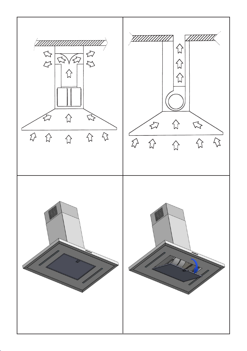
Bloccaggio valvola
Attenzione! Prima di collegare il tubo essibile
uscita aria al motore, accertarsi che la valvola di
non ritorno posta sulla bocca del motore sia libe-
ra di roteare.
VERSIONE MOTORE REMOTO
Nel caso di motore esterno collegare il cavo del
gruppo motore nell’apposita morsettiera presente
nella scatola in plastica indicata in g. 13.
Fare attenzione nel rispettare i colori dei cavi du-
rante il collegamento elettrico.
FUNZIONAMENTO
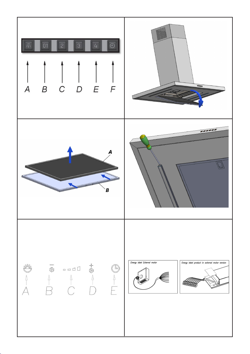
Mod. SIL-Modulo versione lusso (dis. 8)
A: Interruttore on/off luce
B: Interruttore on (I velocità)/off motore
C: Interruttore II velocità
D: Interruttore III velocità
E: Interruttore IV velocità
F: Temporizzatore 10 minuti
Mod. SIL TC - versione Touch Control
(Dis.12)
A: INTERRUTTORE ON/OFF LUCI
B: RIDUZIONE VELOCITA’/ OFF MOTORE
C: INDICATORI VELOCITA’
D: ON MOTORE / AUMENTO VELOCITA’
E: TEMPORIZZATORE 10 min.
La pulsantiera Touch Control permette di im posta-
re la funzione desiderata sorando il relativo tasto.
Le spie luminose (C) posizionate al centro della
pulsantiera indicano la velocità di aspi razione im-
postata.
Nel caso di errato funzionamento della pulsantie-
ra, premere due volte il tasto di colore rosso visi-
bile all’interno della cappa dopo la rimozione del
ltro antigrasso.
Se il prodotto SILTC rimane privo di alimentazione
elettrica, al momento del ripristino delle funzioni ri-
chiede 15 secondi per l’auto diagnosi, nel frattem-
po potrebbe non funzio nare correttamente.