Dake SL921 Quick start guide

ISTRUZIONIPERINSTALLAZIONEUSOEMANUTENZIONE
INSTALLATION,USEANDMAINTENANCEINSTRUCTION
IT
GB
INFORMAZIONICOMMERCIALIPERICONSUMATORI
COMMERCIALINFORMATIONFORTHECONSUMER
INFORMAZIONITECNICHE
TECHNICALINFORMATION
TYPE:FSEC
SL921LEDSTRIP
ENERGYLABEL

2

3
Ilsimbolosulprodottoosullaconfezioneindicacheilprodottonondeveessere
consideratocomeunnormaleriutodomestico,madeveessereportatonelpunto
di raccolta appropriato per il riciclaggio di apparecchiature elettriche ed elettro-
niche.Provvedendoasmaltirequestoprodottoinmodoappropriato,sicontribu-
isceaevitarepotenzialiconseguenze negativeperl’ambienteeperla salute, che
potrebberoderivaredaunosmaltimentoinadeguatodelprodotto.Perinformazio-
ni più dettagliate sul riciclaggio di questo prodotto, contattare l’ucio comuna-
le, il servizio locale di smaltimento riuti o il negozio in cui è stato acquistato il
prodotto. Questo elettrodomestico è marcato conformemente alla Direttiva Euro-
pea 2012/19/EC sui riuti da apparecchiature elettriche ed elettroniche (WEEE).
IT
Thesymbolontheproductoronitspackagingindicatesthatthisproductmaynotbe
treatedashouseholdwaste.Insteaditshallbehandedovertotheapplicablecollection
pointfortherecyclingofelectricalandelectronicequipment.Byensuringthisproduct
isdisposedofcorrectly,youwillhelppreventpotentialnegativeconsequencesforthe
environmentandhumanhealth,whichcouldotherwisebecausedbyinappropriate
wastehandlingofthisproduct.Formoredetailedinformationaboutrecyclingofthis
product,pleasecontactyourlocalcityoce,yourhouseholdwastedisposalserviceor
theshopwhereyoupurchasedtheproduct.Thisapplianceismarkedaccordingtothe
Europeandirective2012/19/EConwasteelectricalandelectronicequipment(WEEE).
GB

4
12
6
3 4
5

7
10
8
9
5
11 12

13 14
15
6

INDICE
Avvertenze
Versionid’uso
Installazione
Funzionamento
Manutenzione
7
IT

Vericare che tutti i compo-
nenti non siano danneggiati,
incasocontrariocontattareil
rivenditore e non proseguire
conl’installazione.
Primadiinstallareilprodotto
leggereattentamentetuttele
istruzionidiseguitoriportate:
- Utilizzare un tubo eva-
cuazione aria che abbia la
lunghezza minima possibi-
le, limitato numero di curve,
materialeapprovatonormati-
vamente.
-Evitarecambiamentidrastici
disezione(diametrocostante
consigliatoØ150mmopari
supercie).
Per il mancato rispetto delle
precedenti istruzioni la ditta
fornitricenonrisponderàper
problemi di portata o di ru-
morosità e nessuna garanzia
saràprestata.
* I bambini e le persone
inesperteoidisabiliposso-
no utilizzare l’apparecchio
solo sotto la supervisione
diadulti.
*La distanza minimatrala
superciedelpianodicot-
turaelaparteinferioredel
lacappadeveessere65cm.
*L’ariaraccoltanondevees-
sereconvogliatainuncon-
dottousatoperloscarico
8
AVVERTENZE di fumi di apparecchi ali-
mentaticonenergiadiversa
daquellaelettrica(impianti
di riscaldamento centraliz-
zati,termosifoni, scaldaba-
gni,ecc.).
* Per lo scarico dell’aria
da evacuare rispettare le
prescrizioni delle autorità
competenti.
*Prevedereun’adeguataare-
azionedellocalequandouna
cappaedapparecchialimen-
tati con energia diversa da
quella elettrica (stufe a gas,
adolio,acarbone,ecc.),ven-
gono usati contemporanea-
mente.
La cappa aspirante evacuan-
do l’aria potrebbe creare
una pressione negativa nella
stanza.Lapressionenegativa
dellocalenondevesupera-
rei0,04mbar,evitandocosì
ilrisucchiodeigasdiscarico
dellafontedicalore.
Pertantobisognaattrezzareil
locale con delle prese d’aria
chealimentinounussoco-
stantediariafresca.
* Nell’operazione di collega-
mento elettrico assicurarsi
che la presa di corrente sia
munitadicollegamentoater-
ra e vericare che i valori di
tensione corrispondono con
quelli indicati nella targhetta
all’internodell’apparecchio.

*Primadiprocedere aqual-
siasi operazione di pulizia o
manutenzione è necessario
togliere l’apparecchio dalla
rete.
Sel’apparecchiononèprov-
visto di cavo essibile non
separabileedispina,odial-
tro dispositivo che assicuri
la omnipolare disinserzione
dalla rete, con una distan-
zadiaperturadeicontattidi
almeno 3 mm, allora tali di-
spositividiseparazionedalla
rete devono essere previsti
nell’istallazionessa.
Se l’apparecchio è provvisto
di cavo alimentazione e di
spina, deve essere posto in
modo che la spina sia facil-
menteaccessibile.
* Evitare l’uso di materia-
li che causano ammate
(ambè) nelle immediate
vicinanze dell’apparecchio.
Nel caso di fritture fare
particolarmente attenzione
al pericolo di incendio che
costituiscono olio e grassi.
Particolarmente pericoloso
per la sua inammabilità è
l’olio già usato. Non usare
griglie elettriche scoperte.
Per evitare un possibile ri-
schio di incendio attenersi
alleistruzioniindicateperla
pulizia dei ltri antigrasso
e la rimozione di eventuali
depositi di grasso sull’ap-
parecchio.
9
VERSIONID’USO
L’apparecchio è già predisposto sia per la
versioneltrantesiaperlaversioneaspirante.
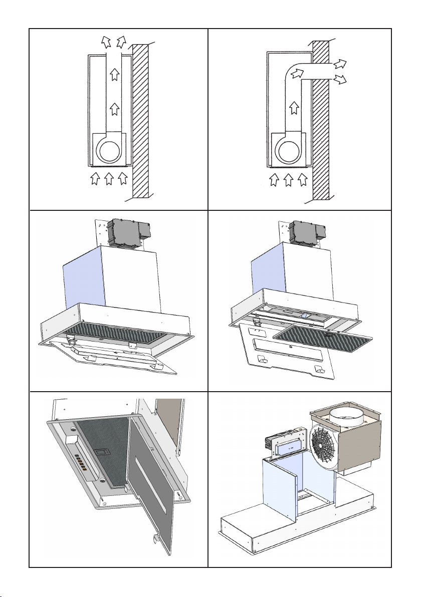
*Nellaversioneltrante(dis.1)l’ariaedi
vaporiconvogliatidall’apparecchio,vengo-
nodepuratisiadaunltroantigrassosiada
un ltro al carbone attivo e rimessi in cir-
colazione nell’ambiente attraverso un foro
praticatonellapartesuperioredelpensile.
Illtrocarbonevienefornitoseparatamente
alprodotto.
*Nellaversione aspirante(dis.2)ivapori
vengono convogliati direttamente all’ester-
no,tramiteuncondottodievacuazioneche
sicollegaconlapartesuperioredellaparete
odelsotto.L’utilizzodelltroalcarbone
nonènecessario.

10
Uscitaariaposteriore
Imodelliconunsolomotorepossonoessere
installaticonl’uscitaariadelmotorerivolta
versoillatoposterioredelprodotto.
Nel caso si intenda usare questa opzione
occorrerimuovereilsupportomotoreagen-
dosulle18viti(g.6),estrarreeruotareil
supporto,posizionarlonellasuasedeman-
tenendol’uscitaariarivoltaversoillatopo-
sterioredelprodotto(g.7).
Fissarloconlevitirimosseinprecedenza.
Bloccaggiovalvola
Attenzione! Prima di collegare il tubo es-
sibileuscitaariaalmotore,accertarsichela
valvoladinonritornopostasullaboccadel
motoresialiberadiroteare.
*Versioneaspirante
Collegare la angia della cappa al foro di
evacuazione tramite un tubo adatto. Eet-
tuare il collegamento elettrico mediante il
cavoalimentazione.
*Versioneltrante
Collegare alla angia un tubo adatto che
convogli l’aria no alla parte superiore del
pensile. Eettuare il collegamento elettrico
medianteilcavoalimentazione.
Installazionedeicamini
Posizionare i camini in acciaio nelle loro
sede,sopralacappa,sollevareilcaminosu-
periorenoaraggiungerelapartesuperiore
delpensile(g.11),tracciareconunamati-
ta dei riferimeti sulla posizione del camino
(g,.12).
Abbassare il camino superiore e posizio-
narelastaadisupportodelcaminocome
dag.13,incorrispondenzadeiriferimenti
tracciatiinprecedenza.
Fissarelastaametallicadisupportodeica-
minicomedagura.14
Alzareilcaminosuperiorenoaraggiunge-
relastaadisupportosstainprecedenza
quindi, bloccare mediante le viti fornite in
dotazione,comedag.15.
INSTALLAZIONE
Primadiprocedereall’installazione,perevi-
taredannidell’apparecchio,disinserireiltri
antigrasso.
Si dovrà procedere aprendo prima il vetro
ruotandolocomedagura3;quindirimuo-
vereiltriantigrasso,agendosull’apposita
maniglia,ruotandolinoall’estrazionedalla
lorosede(g.4).
Realizzareun’aperturasulfondodelpensile
delledimensioniparia:
SL921520:500mmX270mm
SL921780:760mmX270mm
Accertarsi che la struttura del pensile ed il
materialeconcuièstatorealizzatopermet-
tanol’esecuzioneditaleaperturasenzacau-
saredanni,anchenelcorsodell’installazione
delprodotto.
Predisporre l’alimentazione elettrica all’in-
ternodelpensile.Predisporrel’evacuazione
ariasiacheilprodottosiainstallatoinmo-
dalitàaspirantecheltrante.
Utilizzare un tubo di evacuazione aria che
abbia la lunghezza massima non superiore
a5metri.
Limitare il n° di curve nella canalizzazione
poichéognicurvariducel’ecienzadiaspi-
razioneequiparataa1metrolineare.(Es:se
siutilizzanon°2curvea90°lalunghezza
della canalizzazione non deve superare i 3
metri).
Evitare cambiamenti drastici di direzione.
Utilizzareuncondottocondiametro150mm
costantepertuttalalunghezza.
Utilizzareuncondottodimaterialeapprova-
tonormativamente.
Inserireilprodottonelpensileessarlome-
diantelevitiforniteindotazione,attraverso
leforaturecomedag.5.
Sianellatoanteriorecheposterioredelpro-
dotto.

* Un’accurata manutenzione garantisce un
buonfunzionamentoedunbuonrendimen-
toneltempo.
*Unacuraparticolarevarivoltaalltroan-
tigrasso.
La rimozione del ltro avviene operando
sull’apposita maniglia spingendola verso la
parte alta della cappa e facendo ruotare il
ltro verso il basso sganciandolo dalla sua
sede(dis.4).Illtrovieneinseritonell’ope-
razioneinversa.
Dopo30oredieserciziodellacappalapul-
santiera, segnalerà la saturazione del ltro,
mediantel’illuminazionedituttiitasti.Peril
reset,schiacciareiltastotemporizzatore.
La pulizia del ltro antigrasso può essere
eseguitaamanooinlavastoviglieaprodotto
spento.
Lapuliziaavvieneinrapportoall’uso,alme-
nounavoltaogniduemesi.
*Nelcasod’usodell’apparecchioinversione
ltrante,ènecessariosostituireilltrocar-
boneattivo(g.9)periodicamente.
Illtrodicarbonesirimuovetogliendopri-
mailltroantigrasso(dis.4)epoi tirando
l’appositalinguettainplasticadelltrocar-
bonesganciandolodallasuasede.Illtroal
carbonevieneinseritonell’operazioneinver-
sa.Lasostituzione delltroal carboneav-
vienein rapporto all’uso, almeno una volta
ogniseimesi.
*Perlapuliziadell’apparecchiostessovie-
neconsigliatol’usodiacquatiepidaedeter-
sivoneutro,evitandol’usodiprodotticon-
tenentiabrasivi.Perlapuliziadiapparecchi
inacciaiovieneconsigliatol’usodiprodotti
specializzati,seguendoleistruzioniindicate
sulprodotto.
SOSTITUZIONEDELLABARRALED.
Perlasostituzione dellabarraledsiconsi-
gliadirimuovereillistelloinmetallo come
dagura10.
Sostituirelabarraledconunadiparecarat-
teristiche.
Ripristinareillistellometallicoalprodotto.
* La sostituzione del cavo alimentazione
deve essere eseguita esclusivamente da
personaleautorizzato.
11
FUNZIONAMENTO
Mod.SL921(g.8)
A:Interruttoreon/oluce
B: Interruttoreon(I°velocità)/omotore
C:InterruttoreII°velocità
D:InterruttoreIII°velocità
E: InterruttoreIV°velocità
F: Temporizzatore10minuti
TEMPORIZZAZIONI
Conl’entratainvigoredal1°Gennaio2015
dei nuovi regolamenti della Commissione
EuropeaEU65“Energylabel”eEU66 “ Eco-
design”,abbiamoresoconformeiprodottiin
baseairequisitirichiesti.
Tuttiimodellinelleversionienergylabeldi-
spongonodiunaelettronica,confunzionidi
temporizzazionedellevelocitàdiaspirazio-
ne,superiorea650m3/h.
Ineettiimodelliconmotoreabordo,con
portatamassimasuperiorea650m3/h,pre-
vedonolaIVavelocitàtemporizzatadopo6
minuti di funzionamento, Trascorsi i tempi
di cui sopra il motore di aspirazione passa
allaIIIavelocitàinmanieraautomatica.
Ilprodottoinmodalitàstand-byhauncon-
sumoinferiorea0.5W.
SETTAGGIOTEMPERATURACOLORE
Assicurarsicheleluciedilventilatoresiano
spenti.
TenendopremutoiltastoTIMER,vieneac-
cesalalucenellatemperaturacoloreimpo-
statainprecedenza.
PremereemantenerepremutoiltastoLuce
pervariarelatemperaturacolore.
Fintanto che il tasto viene mantenuto pre-
muto,vienevariatalatemperaturacoloreda
calda a fredda, basta lasciare il tasto Luce
perselezionareilcoloredesiderato.
Usciredallafunzionediselezionedellatem-
peraturacolorepremendoiltastoON/OFF.
MANUTENZIONE

CONTENTS
Warnings
Uses
Installation
Working
Maintenance
12
GB

energy other than electric
power(eg.centralizedhea-
ting, radiators, water-hea-
ters,etc.).
*Toevacuatetheairoutlet,
pleasecomplywiththeper-
tainingrulesgivenbycom-
petentauthorities.
* Provide the room with an
adequateaerationwhenaco-
okerhoodandappliancesfed
byenergyotherthanelectric
power (gas-, oil-, or coal-
stoves, etc.) are used simul-
taneously. The cooker hood,
when evacuating the sucked
air,couldgenerateanegative
pressurein theroom-which
can’texceedthelimitof0.04
mbar, in order to avoid the
suck of exhausts deriving
fromtheheat-source.There-
foretheroomshouldbepro-
vided with air-intakes to al-
lowacostantowoffreshair.
*Whenperformingtheelectrical
connections on the appliance,
pleasemakesurethatthecur-
rent-tapisprovidedwithearth
connectionandthatvoltageva-
lues correspond to those indi-
catedonthelabelplacedinside
theapplianceitself.
13
WARNINGS
Beforeinstallingtheapplian-
ce,makesurethatnoneofthe
partsisdamagedinanyway.
In case of damaged parts,
contact your retailer and do
notproceedwithinstallation.
Read all of the following in-
structions with care before
installingtheappliance.
-Useanairoutletpipeofthe
shortestpossiblelength.
- Limit the number of pipe
bends.
-Useamaterialapprovedby
standardsandregulations.
- Avoid any sudden changes
in pipe section (recommen-
ded constant diameter: 150
mmorequalsurfacearea).
* The appliance is not in-
tended for use by young
children or inrm persons
withoutsupervision.Young
children should be super-
visedtoensuretheydonot
playwiththeappliance.
* The cooker surface and
theinferiorpartofthecoo-
kerhoodmustbeatamini-
mundistanceof65cm.
* The air sucked can’t be
conveyedthroughorintoa
ductusedtoletoutfumes
fromappliancesfedby

14
USES
The appliance is already arranged both for
lteringandforsuctionperformances.
*Initslteringversion(Fig.1),theairand
fumesconveyedbytheappliancearedepu-
red both by a grease lter and by an acti-
vecoallter,andputagainintocirculation
throughtheholemadeonthetopoftheca-
binet.
The charcoal lter is not supplied with the
appliance.
* In its sucking version (Fig. 2), fumes are
directly conveyed outside, through an eva-
cuationductconnectedwiththesuperiorpart
ofthewallortheceiling.Bothcoallterand
airdeectorarenotnecessaryinthiscase.
*Beforecarryingoutanycle-
aning or maintaining ope-
rations, the appliance ne-
eds to be removed from the
electricgrid.If the appliance
is not provided with a non-
separable exible cable and
plug, or with another device
ensuring omnipolar discon-
nections from the grid, with
anopeningdistancebetween
thecontactsofatleast3mm,
then such disconnecting de-
vicesmustbesuppliedwithin
thexedinstallation.
Ifthexedapplianceisendo-
wedwithasupplycordanda
plug,theappliancehastobe
putinaplacewheretheplug
canbereachedeasily.
*Theuseofmaterialswhich
canburstintoamesshould
be avoided in close proxi-
mityoftheappliance.When
frying,pleasepayparticular
attentiontoreriskdueto
oilgrease. Beinghighlyin-
ammable,friedoilisespe-
ciallydangerous.Donotuse
uncovered electric grills.
In order to avoid possible
rerisk,allinstructionsfor
grase-ltercleaningandfor
removing eventual grease
deposits should be strictly
followed.

15
INSTALLATION
Remove the grease lters before installing
theproduct,inordertoavoidtodamagethe
appliance.
Opentheglassbyrotatingitasshowning.
3; then remove the grease lters by acting
ontheirspecichandle androtatethemto
removethemfromtheirseating(g.4).
Makeanopeningonthekitchencabinetbot-
tomofthefollowingsizes:
SL921520:500mmX270mm
SL921780:760mmX270mm
Makesurethecabinetstructureandthema-
terial used allow you to make this opening
without causing any damages, even during
theapplianceinstallation.
Preparethepowersupplyinsidethecabinet.
Prepare the air discharge hole for the pro-
ductbeinginstalledeitherinthesuckingor
lteringmode.
Useanairdischargepipewhosemaximum
lengthdoesnotexceed5meters.
Limitthenumberofelbowsinthepiping,as
each elbow reduces the air capacity of the
hoodofabout1linearmeter.(Eg.:ifyouuse
no.2x90°elbows,thelengthofthepiping
shouldnotexceed3meters).
Avoid abrupt direction changes. Use a
150mmconstantdiameterpipeforthewho-
lelength.Usepipingapprovedstandardsin
force.
Placetheapplianceinsidethecabinetandx
itbyinsertingthescrews suppliedintothe
holes,asshowning.5.
Both in the front and rear side of the ap-
pliance.
Rearairoutlet
Modelsequippedwithonlyonemotorcanbe
installedhavingthemotorairoutletorien-
tedtowardstheappliancerearside.
If you choose this option, you will need to
removethemotorsupportbyremovingthe
18 screws (g. 6), taking out and rotating
thesupport,placingitinitshousing,always
keepingtheairoutletorientedtowards the
appliancerearside.(g.7).
Secureitbyusingthescrewspreviouslyre-
moved.
Blockingofthestopvalve
Warning! Before connecting the exible
exhaustingpipetothemotor,makesurethe
stopvalve,whichisontheairoutletofthe
motor,canswing.
Exaustingversion
Connect the ange to the exhausting hole
with an appropriate pipe. Connect the ap-
pliancewiththeelectricalmainsthroughthe
supplycord.
Filteringversion
Connect the ange with a pipe suitable to
conveytheairtothetopofthecabinet.Con-
necttheappliancewiththeelectricalmains
throughthesupplycord.
Chimneyinstallation
Lifttheinternalsteelchimneyuptothetop
ofthewallunit(g.11),drawwithapencil
therearendoftheinternalchimneyonboth
sides(g.12),lowertheentirechimneyan-
dposi tion the xing bracket in correspon-
dencewiththemarkingmade(g.13),se-
curethebracketwithscrews(g.14).
Lifttheinternalchimneyuptocoverthebra
cketandsecureitwithscrewspositionedon
bothsides(g.15).

16
WORKING
Mod.SL921(g.8)
A: Lightswitchon/o
B: Motorswitchon/o(1stratelevel)
C: 2ndratelevelswitch
D:3rdratelevelswitch
E: 4thratelevelswitch
F:10-minutetimer.
TIMING
AsaresultofthenewEU65“Energylabel”and
EU66“Ecodesign”regulationsissuedbythe
EuropeanCommission,whichcameintoforce
asfromJanuary1st,2015,ourproductshave
beenadaptedtocomplywiththesenewre-
quirements.
Allofthemodelscomplyingwiththeenergy
label requirements, are equipped with new
electronicsincludingatimerdeviceforsuc-
tionspeedscontrol,whentheaircapacityex-
ceeds650m³/h.
Internal motor models, with maximum air
capacity higher than 650m³/h, are equip-
ped with a timer device that automatically
switches the suction speed from 4th to 3rd
speed,after5minutesoperation.
Theenergyconsumptionoftheappliancein
stand–bymodeislowerthan0.5W.
COLOUR TEMPERATURE SETTING
Make sure that the lights and the fan are off.
Holding down the TIMER key will turn on the light
at the previously set colour temperature.
Press and hold the Light key to change the colour
temperature.
As long as the key is kept pressed, the colour
temperature is changed from warm to cold, just
leave the Light key to select the desired colour.
Exit the colour temperature selection function by
pressing the ON/OFF key.
MAINTENANCE
*Anaccuratemaintenanceguaranteesgood
functioningandlong-lastingperformance.
* Particular care is due to the grease lter
panel.Itcanberemovedbypushingitsspe-
cialhandletowardtheback-sideoftheco-
okerhoodandturningthelterdownwards
sotounfastenitfromitsslot(Fig.4).
Toinsertthelterjustperformtheopposite
operation.
After 30 hours working (model), the push
buttoncontrolpanelwill signalthesatura-
tion of the grease lter by lighting all the
buttons.Pressthetimerbuttontoreset.
The grease lter needs cleaning by regular
hand-washing or in dishwashers every two
monthsatleastordependingonitsuse.
*Incasetheapplianceisusedinitsltering
version,theactivecoallter(Fig.9)needs
to be periodically replaced. The coal lter
canberemovedbyremovingthegreaselter
rst(Fig.4),andbypullingitsspecialplastic
tongue until it is unfastened from its slot.
Re-insertthecoallterbyoperating inthe
oppositeway.Thecoallterneedsreplacing
dependingontheuse,buthowevereverysix
monthsatleast.
* To clean the appliance itself tepid water
and neutral detergent are recommended,
whileabrasiveproductsshould be avoided.
For steel appliances specialized detergents
arerecommended(pleasefollowtheinstruc-
tionsindicatedotheproductitselftoobtain
thedesiredresults).
LEDBARREPLACEMENT
Toremovetheledbar,itisrecommended
toremovethesteelbarasshowninFig.10.
Replace the led bar with one of the same
characteristics.
Retthesteelbar.
*Ifthesupplycordisdamaged,itmustbe
replacedbythemanufactureroritssevi-
ceagentorasimilarlyqualiedpersonin
ordertoavoidahazard.

17

18


00000000000 - 05/19
Table of contents
Languages:
Other Dake Ventilation Hood manuals
Popular Ventilation Hood manuals by other brands

U.S. Products
U.S. Products HHP-310 Information & operating instructions

Pando
Pando E-201 installation manual

Heartland
Heartland 3400 user manual

KitchenAid
KitchenAid KVUC606J55 Installation Instructions and Use & Care Guide

Bosch
Bosch DUH30162UC use and care manual

Bosch
Bosch DHE645MGB Operating and installation instructions

Teka
Teka DMR 75 Series instruction manual

Sirius Satellite Radio
Sirius Satellite Radio FSED Installation, Use and Maintenance Instruction

Thermador
Thermador VTI1010W installation instructions

Electrolux
Electrolux WHGL9040CN installation manual

Zephyr
Zephyr Pisa ZPI-E24AG290 Use, care and installation guide

THERMEx
THERMEx Turbo K702 II User instructions