H9Q/H9QD User Manual
Author: CNR Revised by: MES Rev: 05/05/21 Page 3 of 12
The AgCam® and EnduraCam® camera lines are a durable, reliable surveillance system with the innovative ability to be quickly
moved from one application to the next.
II. STANDARD FEATURES
•Feature the latest in Analog HD technology
•View 1, 2, 3 or 4 cameras at the same time
•LED backlit
•Compatible with NTSC or PAL cameras, not simultaneously
•Advanced LCD technology allows you to clearly see your image from any angle
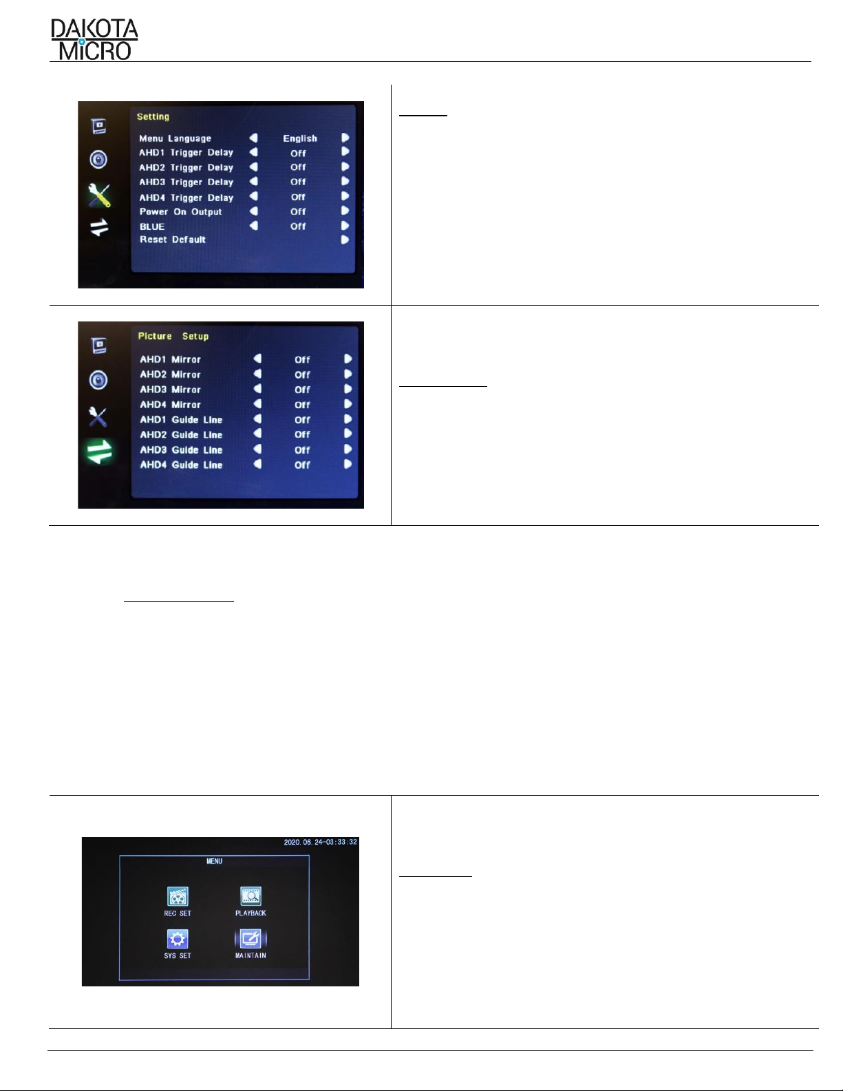
•Mirror the view of any of your cameras for use as a backup camera
•2 Year Warranty
•16:9 aspect ratio
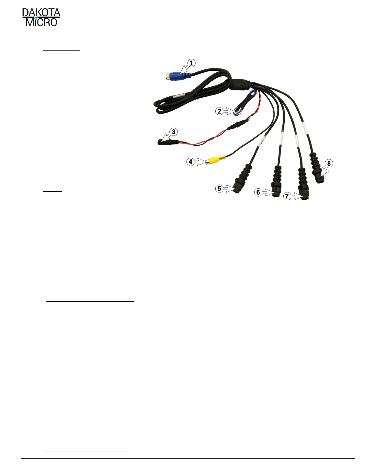
•4 Camera Inputs
•Records up to 4 cameras simultaneously or independently onto SD card for easy transfer of files
•Available in 7in or 9in size
•Event triggers for each camera allow for triggered events to bring your camera to full view (IE: putting the vehicle in
reverse)
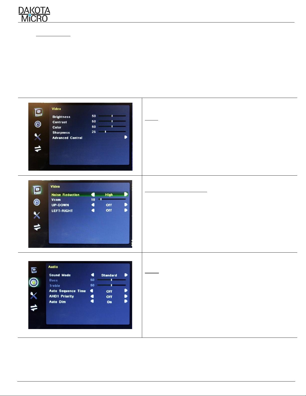
•Color, brightness, contrast, and volume controls that allow compensation for use in different environments
•Remote control, sun shield, and metal U-bracket monitor stand included
III. IMPORTANT INFORMATION REGARDING ANALOG AND AHD EQUIPMENT
•For multi-camera systems, all cameras must be either AHD or Analog.
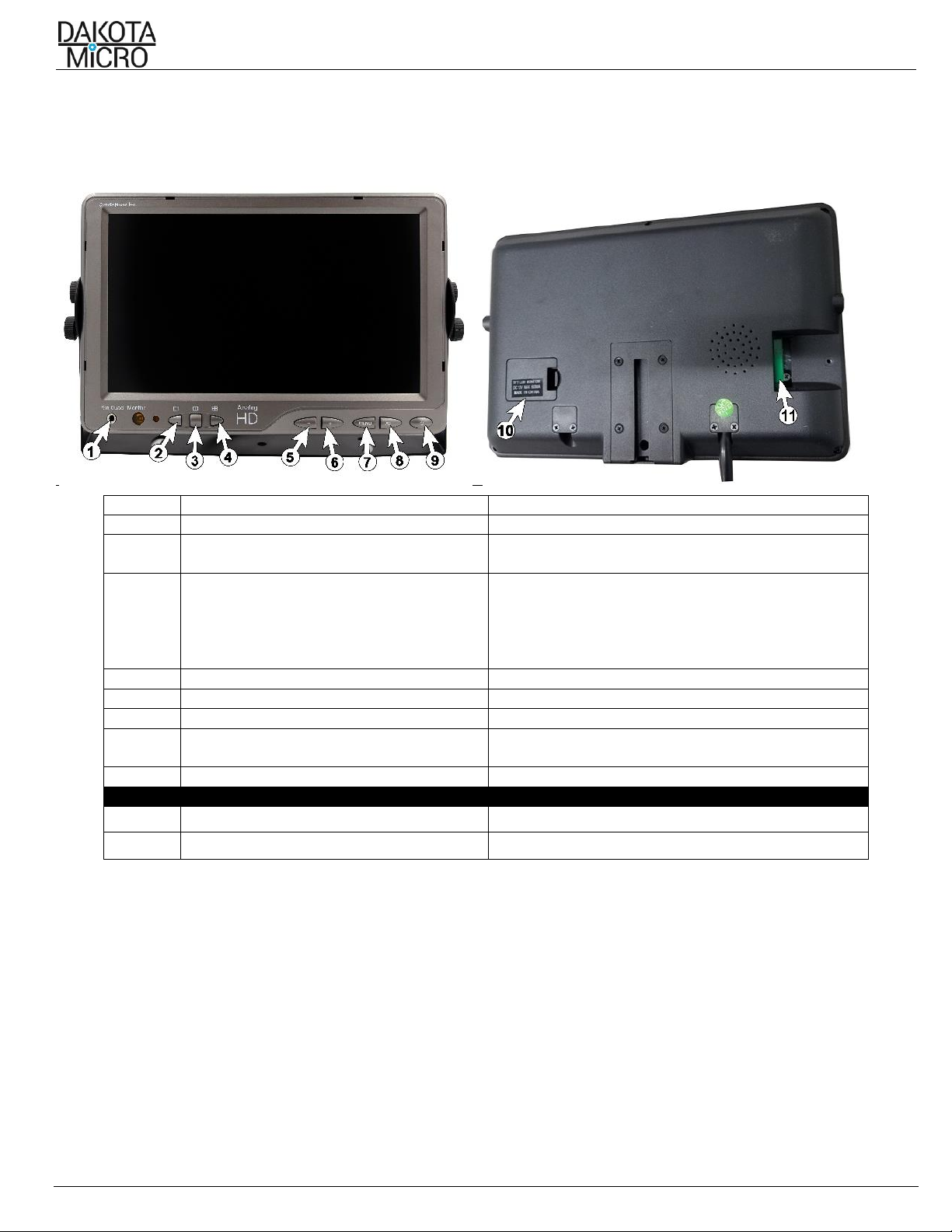
IV. MONITOR INSTALLATION & MOUNTING
A. Mounting Precautions
Remove your monitor carefully from packaging and inspect all mounting hardware. Mounting location is the most
important part of the monitor installation as it ensures you the maximum visual benefit from your AgCam® system. With
that said, when installing your monitor, ensure to follow these three (3) precautions:
1. The monitor is out of direct sunlight. This will prolong the life of the unit as well as ensure optimum visibility.
2. The monitor does not obstruct view.
3. The monitor does not interfere with the normal operation of equipment.
WARNING:
Dakota Micro, Inc. is not responsible for any damages caused to your monitor, or yourself, due to the improper installation or
use of a suction cup monitor mount, whether it be product sold by DM or product purchased from another source.
B. Universal Bracket Mounting
1. Hold monitors U-bracket in place on monitor.
2. Attach bracket with included wing bolts.
C. Finalizing Universal Bracket Installation
1. With the mount and monitor attached, find and
mark the desired position for the monitor.
2. Remove the monitor from the mount.
3. Attach the monitor to the mount and tighten
the wing nuts.
*Use ONLY the nuts included in the kit, bolts longer than 10mm will damage your monitor.
NOTE: Turn the monitor on only after it has been securely mounted, supplied with power, and the cameras are connected