manuals.online logo
Brands
  1. Home
  2. •
  3. Brands
  4. •
  5. Daktronics
  6. •
  7. Clock
  8. •
  9. Daktronics BB-2114 User guide

Daktronics BB-2114 User guide

Shot Clock Installation Quick Guide Page 1 of 2
DD5071871
Rev 00
31 May 2022
201 Daktronics Drive
Brookings, SD 57006-5128
www.daktronics.com/support
800.325.8766
Before Beginning
Consult the regulations and guidelines for your state regarding acceptable shot clock mounting location(s).
Locate and unpack all boxes that contain shot clocks and related equipment, including start/stop switches and
optional radio receivers.
For more information regarding safety, installation, or operation, refer to the Tuff Sport & Colorsmart Indoor
LED Scoreboards Installation Manual (DD2481645), shipped with the shot clocks and available online at
www.daktronics.com/manuals.
Note: Due to the variety of wall materials and backstop manufacturers used in basketball facilities, Daktronics
cannot anticipate a user’s individual installation needs or provide mounting hardware suitable for every
installation. Choose a method of installation that will safely support the weight of the display. Daktronics is
not responsible for the integrity or suitability of mounting systems manufactured and installed by others.
Recommended Hardware*
Backstop Mounting
• 2"x2"x1/4" Steel Angle;
length varies by width
of shot clock model
• 3/8" bolts @4
• 3/8" hex nuts @4
• 3/8" washers @8
• 3/8" lock washers @4
• 1/2" U-bolts @2
• 1/2" nuts @4
• 1/2" washers @4
• 1/2" lock
washers @4
Wall Mounting
• 3/8" washers @4
• 3/8" wall anchors @4
*Quantities shown per single shot clock. Quantity of U-bolts and 1/2" hardware is doubled for two-pole mounting.
Note: If your system includes wireless radio control, install radio receiver(s) BEFORE mounting the shot clock(s).
Refer to Wireless Radio (p.2).
Wall Mounting
1. Lift the shot clock up on the wall where it is to be mounted.
2. Ensure the cabinet is level, and then use the 3/8" mounting holes on the
rear side anges to mark where to drill.
3. Move shot clock out of the way, and drill holes for wall anchors.
4. Secure the shot clock to the wall by attaching mounting hardware
through all holes on the rear side anges of the cabinet to a pre-drilled
hole in the wall. Refer to Figure 1. Ask for assistance as needed to
support the shot clock while mounting.
Tools Required
• Drill/Hammer Drill
• Tape Measure
• Level
• Marker
• Phillips & Flathead screwdrivers
• Step Ladder (Lift recommended)
• Wrenches/Sockets sized
according to hardware
Washer
Pre-Drilled
Hole in Wall
Mounting Hole
Anchor
Figure 1: Shot Clock Wall Mounting
Backstop Mounting - One Pole
1. Measure the diameter of the backstop support pole to determine the
correct size U-bolts needed to secure steel angles to the pole.
2. Use the guidelines below to determine the correct length of steel angles
required to mount the shot clock to the pole. Lengths are based on the
width of the shot clock.
Shot Clock Model Steel Angle Length
BB-2114 33" minimum
BB-2115 40" minimum
3. Place the steel angles level on the rear of the shot clock, and use the
3/8" mounting holes in the side anges of the cabinet as a guide to mark
where to drill on the steel angles.
4. Use the U-bolts as a guide to mark holes on the opposite ends of the
steel angles.
5. Drill all holes in the steel angles for the shot clock mounting hardware and U-bolts.
6. Use the U-bolts and appropriate hardware to loosely secure the steel angles to the support pole.
7. Lift the shot clock up above the backstop and use 3/8" hardware to secure the shot clock to the steel angles.
Refer to Figure 2. Ask for assistance as needed to support the shot clock while mounting.
8. Make nal adjustments to the shot clock position, and then tighten down all U-bolt hardware.
Backstop Mounting - Two Poles
1. Measure the diameter of the backstop support poles to
determine the correct size U-bolts needed to secure steel angles
to the poles.
2. Measure the outside distance between the two poles, and add
a minimum of 4" to determine the correct length of steel angles
required to mount the shot clock between the poles.
3. Place the steel angles level and centered on the rear of the shot
clock, and use the 3/8" mounting holes in the side anges of the
cabinet as a guide to mark where to drill on the steel angles.
4. Use the U-bolts as a guide to mark holes on both outside edges
of the steel angles.
5. Drill all holes in the steel angles for the shot clock mounting
hardware and U-bolts.
6. Use the U-bolts and appropriate hardware to loosely secure the steel angles to the support poles.
7. Lift the shot clock up above the backstop and use 3/8" hardware to secure the shot clock to the steel angles.
Refer to Figure 3. Ask for assistance as needed to support the shot clock while mounting.
8. Make nal adjustments to the shot clock position, and then tighten down all U-bolt hardware.
3/8" Hardware
1/2" Hardware
Steel Angle
U-Bolt w/
Figure 2: Single Pole Mounting
3/8" Hardware
1/2" Hardware
Steel Angle
U-Bolt w/
Figure 3: Two Pole Mounting
Shot Clock Installation Quick Guide Page 2 of 2
DD5071871
Rev 00
31 May 2022
201 Daktronics Drive
Brookings, SD 57006-5128
www.daktronics.com/support
800.325.8766
Power
Only qualied individuals should complete the electrical installation; untrained personnel should not attempt
to install these displays or any of the electrical components. Improper installation can seriously damage the
equipment and be hazardous to personnel.
Shot clocks feature an 11' long 120 VAC power cord with a three-prong plug. Install a grounded receptacle
nearby so that the power cord can easily reach it. If the provided power cord does not reach a grounded
receptacle, it must be re-terminated with a longer cord.
Wired Signal
Wired signal installation requires routing control
cable from the control console to a signal junction
box (J-box) near the display. Refer to Figure 4 for
typical signal layout. At a minimum, use a paired,
22 AWG shielded cable (Daktronics part # W-1077).
1. Connect the cable to a dual 1/4" J-box at the
control console end.
2. Route the cable in conduit from the J-box on
the control console end to a J-box near the shot
clock.
3. Install the 1/4" phone plug (part # 0L-40683)
to the shot clock end of the cable. Be sure to
connect the cable shielding only in the J-box
on this end. DO NOT connect cable shielding at
the J-box near the control console.
4. Insert the plug into the J31 – SIGNAL IN jack
located on the side of the shot clock.
5. Connect a signal cable from the J-box on the
control console end to the J1, J2, or J3 jack on
the rear of the All Sport 5000 console.
6. Connect the Shot Clock Start/Stop Switch (0A-
1196-0031) to the J7 jack on the rear of the All
Sport 5000 console.
Wireless Radio
A wireless radio system requires a radio receiver
mounted inside the shot clock. For more information,
refer to the Gen VI Radio Installation Manual
(DD2362277), provided with the receiver and
available online at www.daktronics.com/manuals.
Radio Settings
By default, radio receivers are set to Broadcast 1
("b1") and Channel 01 ("C1"). This may or may not
match the settings used by existing scoreboards in
the facility. Power ON the All Sport 5000 console to
check the radio settings as shown at right.
J1, J2,
or J3
All Sport Controller
J-Box:
Dual 1/4" Phone
(0A-1196-0013)
Pin Color Function
tip red signal +
ring black signal -
J-Box:
(Not provided by
Daktronics)
Signal Cable:
1 Pair, 22 AWG
(W-1077)
in Conduit
Signal Cable:
1/4" Male Phone to Pigtail, 10'
(0L-40683)
[To Main
Scoreboard]
Signal Cable:
10' (W-1340) 30' (W-1238)
20' (W-1236) 50' (W-1237)
Figure 4: Shot Clock Wired Installation Diagram
Radio Receiver Antenna -
Facing Control Location
All Sport
Controller
with Radio
Option
Up to 500' away with
direct line of sight
Figure 5: Shot Clock Wireless Installation Diagram
RADIO SETTINGS
BCAST 1 CHAN 01
All Sport Radio Settings
If the shot clock radio receiver settings DO NOT need to be changed, skip ahead to Receiver Mounting.
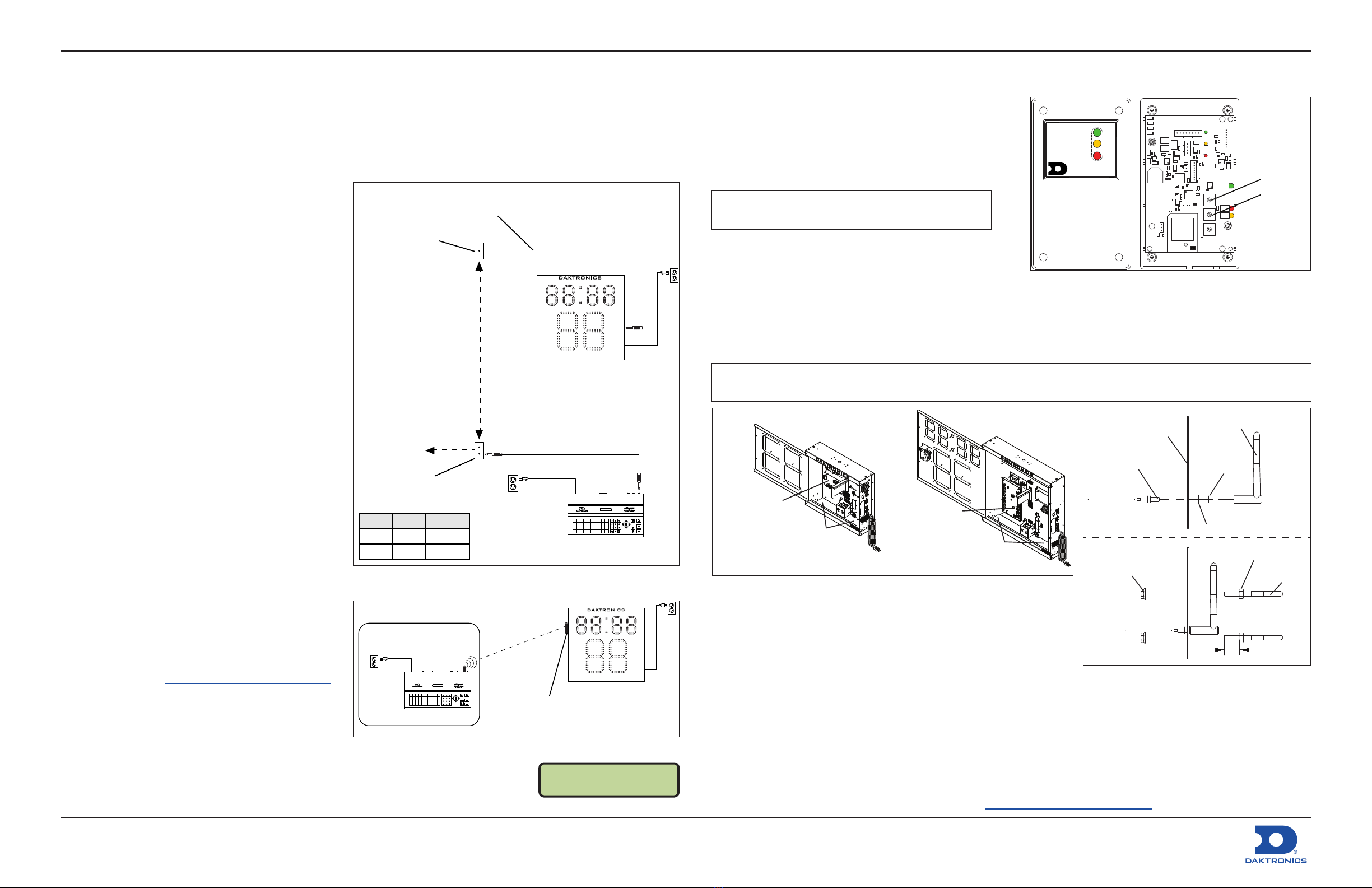
If the shot clock radio receiver Broadcast/Channel settings DO need to be changed:
1. Disconnect power to the shot clock and use a Phillips
screwdriver open the front face panel.
2. Use a Phillips screwdriver to remove the four screws
securing the radio receiver cover.
3. Use a small athead screwdriver to change the BCAST
and CHAN switches accordingly. Refer to Figure 6.
Note: Do NOT change the FUNC switch; this must
always be set to "1".
4. Replace the radio receiver cover.
5. Proceed to Step 2 of Receiver Mounting.
Receiver Mounting
1. Disconnect power to the shot clock and use a Phillips screwdriver to open the front face panel.
2. Use the double-sided adhesive tape to secure the radio receiver inside the bottom of the shot clock cabinet.
Refer to Figure 7. Mount the radio receiver toward the side of the court where the controller is located.
3. Connect the 6-pin cable from the radio receiver to the mating 6-pin J21 jack on the LED driver.
Note: The BB-2114 shot clock will include a 5-pin to 6-pin adapter connected to the 5-pin J45 jack on a wiring
harness coming from the LED driver. Connect the 6-pin cable from the radio receiver to this adapter.
6-Pin Cable
Connection (J21)
6-Pin Cable
Connection (J45)
BB-2115BB-2114
Radio Receiver
& Antenna
Mounting Locations
Radio Receiver
& Antenna
Mounting Locations
Figure 7: Shot Clock Radio Mounting
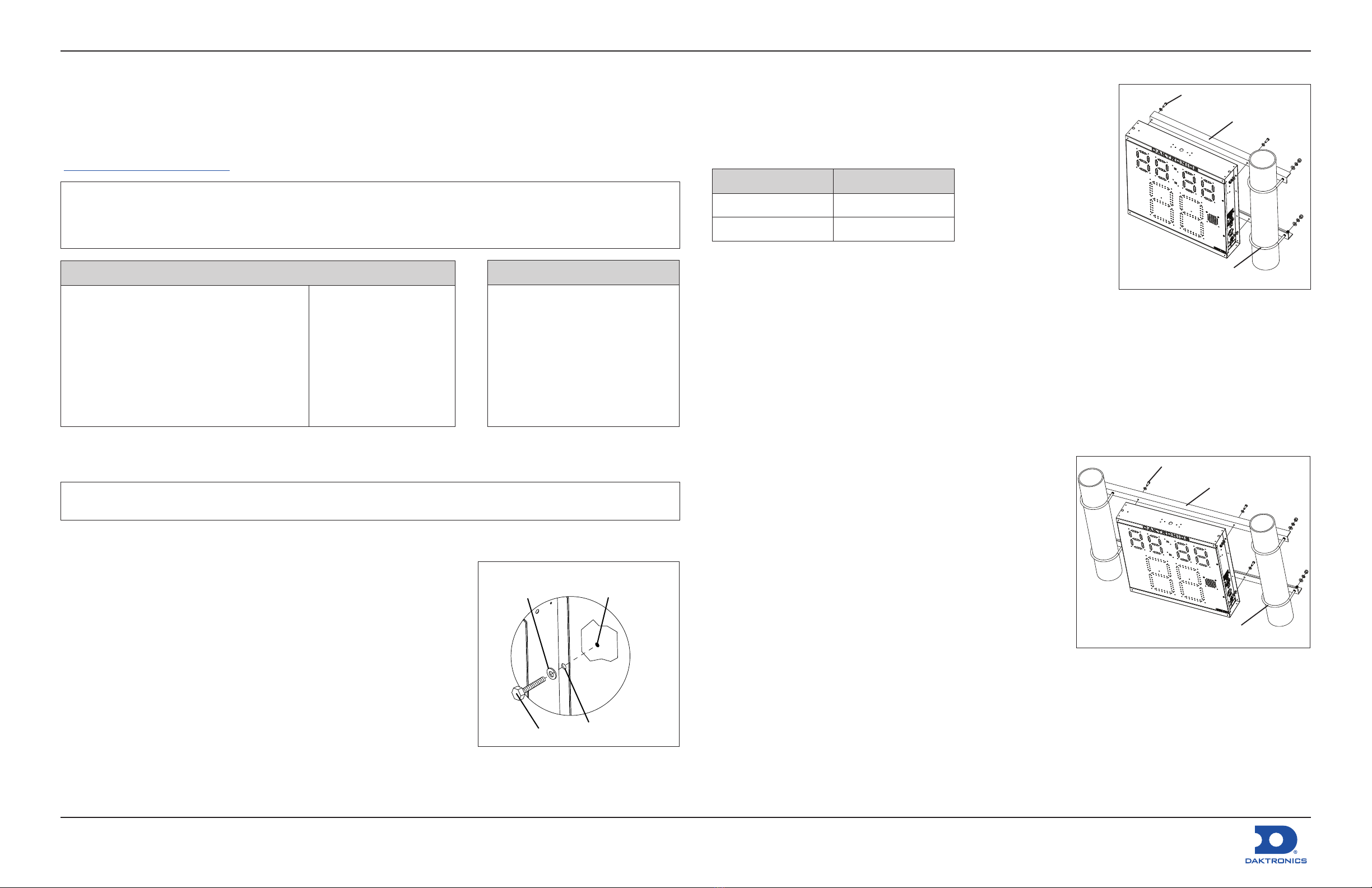
4. Mount the antenna as described below and illustrated in Figure 8:
a. Route the antenna cable through the D hole on the lower side
of the shot clock cabinet. Again, the antenna should be on
the side that faces the control location for best reception.
b. On the outside of the shot clock cabinet, attach the lock
washer, nut, and antenna.
c. Attach the two small U-bolts around the antenna. This is for added protection from ball impacts.
5. Ensure all internal wires are out of the way of getting pinched, and then close and secure the front panel.
6. Power up the shot clock and All Sport 5000 console to test the radio control.
Light Strips
For installations with backboard light strips, refer to the LTS-BB Backboard LED Light Strips Manual (DD4692853),
provided with the light strip kit and available online at www.daktronics.com/manuals.
2.4GHZ
LL-2567
REV 01
POWER
RADIO IN RANGE
DATA OUT
DAKTRONICS
WIRELESS RECEIVER
FUNC CHAN BCAST
X1
X2
J4
0
0
0
1
1
1
Broadcast
Channel
Figure 6: Radio Receiver with and without Cover
Gold Antenna
Connector
Shot Clock
Side Panel
Gold Washer
~3/4"
Gold
Nut
1/4" Black Nut
@4
U-bolt
@2
Antenna
1/4" Nut
@4
Figure 8: Shot Clock Radio Antenna

This manual suits for next models

1

Other Daktronics Clock manuals

Daktronics BB-2140 User manual

Daktronics

Daktronics BB-2140 User manual

Daktronics bb-3140 User manual

Daktronics

Daktronics bb-3140 User manual

Daktronics TI-2031 User manual

Daktronics

Daktronics TI-2031 User manual

Daktronics PC-2001 User manual

Daktronics

Daktronics PC-2001 User manual

Daktronics P2345 User manual

Daktronics

Daktronics P2345 User manual

Daktronics P1348 Instruction Manual

Daktronics

Daktronics P1348 Instruction Manual

Popular Clock manuals by other brands

Velleman WT51 user manual

Velleman

Velleman WT51 user manual

TFA CLOCCO instruction manual

TFA

TFA CLOCCO instruction manual

Lathem DWA Series Setting instructions

Lathem

Lathem DWA Series Setting instructions

Velleman WT51 user manual

Velleman

Velleman WT51 user manual

Extech Instruments 40102F instruction manual

Extech Instruments

Extech Instruments 40102F instruction manual

Mobatime DMU 140 Installation and operating instructions

Mobatime

Mobatime DMU 140 Installation and operating instructions

Casio TQ-379 Operation guide

Casio

Casio TQ-379 Operation guide

Oregon Scientific PRYSMA R manual

Oregon Scientific

Oregon Scientific PRYSMA R manual

Timex 75324T user guide

Timex

Timex 75324T user guide

Sapling SAM Series installation manual

Sapling

Sapling SAM Series installation manual

LFF LWC216 user manual

LFF

LFF LWC216 user manual

MOB MO9410 user manual

MOB

MOB MO9410 user manual

Compumatic TR220D Instruction mamual

Compumatic

Compumatic TR220D Instruction mamual

Trendworx 4044 instruction manual

Trendworx

Trendworx 4044 instruction manual

Hublot SBF8A instruction manual

Hublot

Hublot SBF8A instruction manual

Philips AJ3400 user manual

Philips

Philips AJ3400 user manual

ETT ET-Mini Clock4 manual

ETT

ETT ET-Mini Clock4 manual

CHESS-PLUS AM1401 user manual

CHESS-PLUS

CHESS-PLUS AM1401 user manual

manuals.online logo
manuals.online logoBrands
  • About & Mission
  • Contact us
  • Privacy Policy
  • Terms and Conditions

Copyright 2025 Manuals.Online. All Rights Reserved.