manuals.online logo
Brands
  1. Home
  2. •
  3. Brands
  4. •
  5. DALBO
  6. •
  7. Farm Equipment
  8. •
  9. DALBO MINIMAX User manual

DALBO MINIMAX User manual

DAL·BO
MINIMAX
GB
930cm
Serienummer: 51832-XXXX
DALBO COMPACT 930 cm
Congratulations with your new COMPACT. For safety reasons and to obtain optimaluse ofthe machine you
should read through the following instructions before putting the
machine into operation.
© Copyright 1995. All rights reserved DALBO A/S
Points, which are essential as regards to safety, are marked byV.
V Re-tighten allbolted connections after a few hours use.
V Donot operate the hydraulics without the machine being securely attached toa tractor.
V
Operation must only be carried out from a sitting position in the tractor, andnopersons must
be on or in the close proximity of the machine.
V Must not be operated by children.
V The driver is responsible for correct use of lights and markings according tothe Road Traffic
Aet/ the Highway Code.
V
Itisthe driver' s responsibility to ensure that the capacity of the tractor used is sufficient to
handle the roller properly. Itmust be at least 100 HP
Your Compact has:
Serial number: _ _ _ _ _ _ _ _ _ .Type description: ______ _
Manufacturing month: .Net weight kg:
Please always quote the serial number in connection with any enquiries regarding spare parts.
An index of spare parts, which facilitates the overview of single parts, can be found at the very back.
EU-COMPLAINCE DECLARATION
DALBO A/S
DK-7183 Randbøl
declares herewith that the above machine ismanufactured in accordance with theprovisions of directive 2006/42/EC, which
replaced directive 98/373/EC and change directives 91/368/ECC, 93/44/ECC and 93/68/ECC on harmonisation of member state
legislation concerning health and safety requirements related totheconstruction and manufacture of machines.
hine corresponds to the safety requirements in the European Safety Guidelines.
Date:
Carsten Jensen, CEO
Application:
2
The Compact is used before andaftersowing to break up clods and press down
stones;it also improvesgermination. The Compact can beequipped
with a hydraulically controlled levelling bar, asan optional extra. It makes the
machine very effective on rough-ploughed land.
It is also used with advantage after stubble cultivation, to expedite the rotting of
straw and stubble remains andalso the germination of waste- and weed- seeds.For
rolling very loose soil,it must befitted with at least 50 cmrings.
The Compact is also used for rolling grasslands in the spring.This should bedoneas
soon asthe land can be driven over. Rolling eliminates stones andlumps of earth
from the surface,so that they donot cause obstruction later when the grass is
mowed.At the sametime, the Compact breaks up the surface of the soil, allowing
air to reachthe roots.
V
V
V
Noise:
Dust: V
Handling:
V
The Compact must not be used asa transport vehicle, pile driver, hydraulic press or
the like. Ifyou are in anydoubt, ask your dealer or DALBO.
The Compact must not be used to roll areas of road or similar hard surfaces.
When using the roller the operator must sit in the driver's seat on the tractor, and
there must beno other people eitheronorin the immediate vicinity of the roller.
Theroller may make somenoise when rolling with wom Cambridge rings, but this will
be far below the <langerlimit for tractor drivers.
A lot of dust can be raised during rolling under very dry conditions.
It is recommended that either the tractor doors and windows be closed or a dust
mask wom.
For transport purposes, the roller is supplied in the following separate parts:
830cm
930cm
Middel section, cpl.
1230 kg
1230 kg
Right side section, cpl.
1110 kg
1310 kg
Lefl side section, cpl.
1110 kg
1310 kg
Drawbar incl. rams
450kg
550 kg
2 wheels
62kg
62kg
The parts will be handled with a crane. Hook onto the side sections in the middle of
the squarepipe.
It must be fitted so that it tightens around the pipe during lifting.
3
V On the central section and drawbar yellow sitckers showing a lifting hook
indicate where to hook ontofor effective lifting.
Fitting:
V
Should be carried out in a workshop.See
Fig.7 and8.
A level floor, an approved crane cabable of lifting a minimum of 1000 kg and a
hydraulic pump with a single-acting and a double-acting take-off is required. It must
be able to exert a pressureof atleast 170 bar.
Install the central section vertically on the roller rings and wheel hubs. Fit the
drawbar with the pin in position 15,remember the split pin.
Fit the tilting ram, position 59.
Fit and adjust the support so that the height of the drawbar isapprox. 40 cm.
Connect the tilting ram to a single-acting hydraulic take-off; the hose ismarked
white.
Lift one of the wheel hubs with the cranewhilst carefully allowing the oil to drain out
ofthe ram
This will cause the central section to assume a horizontal position.
Lift each side section into position with the crane hooking onto it as described under
"handling". Secure the side sections with the pins, pos. 35, which are in tum secured
with the screws,pos.36.
Connect the hoses to the folding ram to a double-acting take-off.
Push the folding ram out almost to their full extent and fit, making sure that the
hoses donot cross.
Fit the wheels.
Apply pressure in order to push the folding ram all the way out.
Carefully rock the roller upwards by applyingpressure on the single-acting ram,
making sure that all the hoses are able to move freely.
Carefully retract the roller with the double-acting valve, keeping aneye on the hoses.
Ease the pressure on the single-acting ram sothat the side sections drop down into
their transport bearing.
Secure the hoses to the folding ram with the hose clipsand self-tapping
screws.
Fold the roller in and out a couple oftimes. Keepaneye on the hoses. Thefolding
ramsare throttled opprevent toofast a movement.This isnot of crusial
importance but it may giverise toa whistling soundin the pressure valve on the
hydraulic pump.
Tighten all screws securely, including hub nuts.
Theroller sections areswivelled back to the transport position in the reverse order
toextension.
Start-up:
V
V
Operation:
Maintenance:
4
No adjustments or similar action is necessary before starting to use the
Compact. The roller is drawn by the pickup-hitch of the tractor; which should
be about 40 cmabove the ground.
Remember to secure the draw bolt with a split pin or similar device.
Connect the hydraulic hose (marked white) to a single-acting valve. Connect the
othertwo hoses (marked red) to a double-acting valve.
All the hoses arefitted with 1/2"connectors. If the tractor is not equipped for these,
your dealer can help. A maximumpump pressure of 160bar isrequired.
Defective hoses must be repaired or replaced immediately.A broken hose can in bad
casescause personal injury or mechanical damage to the roller.
All operation must take place fromthe driver's seat andthere must be no-oneelse
in the vicinity of the machine.The changefrom transport to operational mode, and
vice versa, must be made while stationary on more or less levelground,with the
tractor almost idling. Tounfold, operate first the single- acting valve,sothat the
sidesections arelifted clear oftheir transport bearings;usethe double-acting
valvetounfold the side sections completely. Then lower the pressure from the
single-actingvalve, sothat the roller tilts down to the ground. It isadvantageous to
to allow the valves to float freelyduring rolling, if possible.
Toraise the roller, apply the pressure first with the double-acting valve, sothat the
long cylinder acrossthe roller is completely compressed. Then lift the roller
completely vertical with the single-acting valve. Fold the side sections in by means
of the double-acting valve. Lastly,lower them intotheir transport bearings using the
single-acting valve.
Theroller must be raised only for transport. It is not necessary to raise it when
tuming. It can also run backwards in the operating.position.
Recommended speed of travel: 4-5 mph.Moveslowly over stony ground. Tighten all
the screws, and alsobuh nuts, after the first working day.
Chassis - 3 lubrication points - lubricate daily.
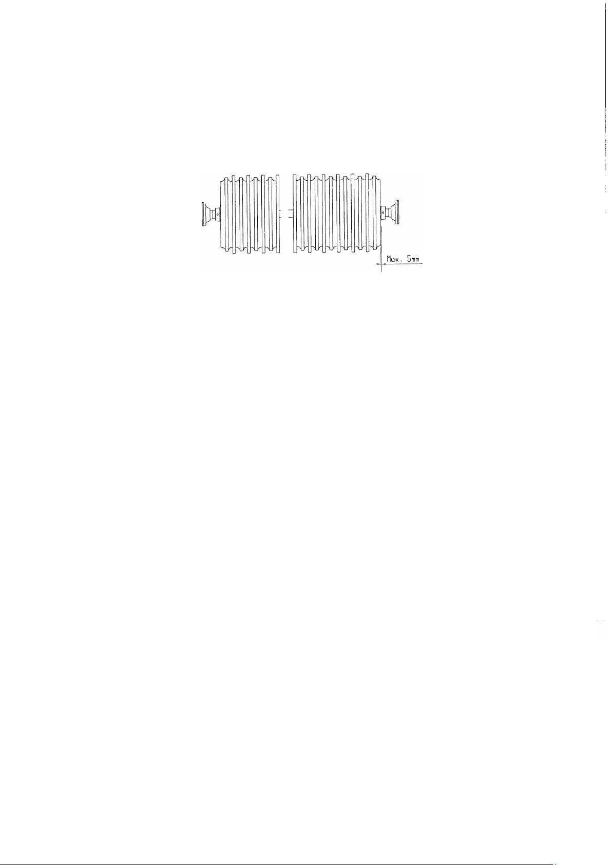
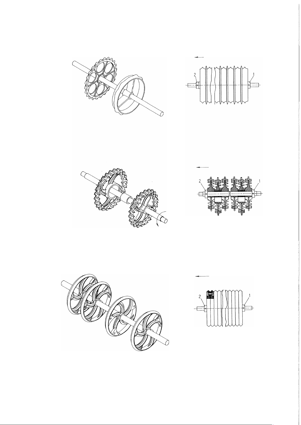
Roller bearings - 6 units - lubricate every 50operatinghours. Lubricate the
wheel bearings onceper season.
Adjust the wheel bearings once a year,followingthe instructions for replace-ment
of bearings, points 1,2,11,12and 13.
5
After the first season the surface of the rings will have wom smooth and they will
therefore take up slightly less space. Adjust the resulting clearance down to max.
5 mm by moving the stop rings (see fig. 1). Remember to tighten the stop ring
screws well. It is advisable to slacken and retighten the screws a couple oftimes
so that they grip better.
Fig. 1:
Check the air pressure in the tyres before the season. It should be 5.2 bar.
For prolonged indoor parking in the transport position, the piston rod should be
lubricated with oil or grease.
REPAIRS:
Wheels: For changing wheels owing to punctures, etc., set the machine in the operating
position. This enables the wheel to be removed without using ajack.
Changing the wheel bearings, see fig. 2.
1. Unscrew the hub cap, pos. 21.
2. Remove split pin pos. 20.
3. Remove lock nut, pos. 19.
4. The axle, pos. 2, can now be knockedout.
5. The bearings, pos. 17and 18, can now be removed.
6. The sealing ring, pos. 16,can now be removed.
7. Install the outer races of the bearings, pos. 17and 18,in the hub housing, item
22.
8. Fit the sealing ring, pos. 16.
9. Mount the inner ring for the bearing, pos.17. on the axle, pos. 2, and
insert the axle in the hub housing.
10. Mount the inner ring for the bearing, pos. 17, on the axle, pos. 2.
11. Screw the lock nut onto the axle, pos. 2, whilst rotating the hub housing, pos.
22. Tighten the lock nut sothat it is difficult to rotate the hub housing, pos.
22. Then slacken the lock nut until the hub housing can again be rotated
without resistance.
12. Fit the split pin, pos. 20.
13. Fit the hub cap, pos. 21.
14. Lubricate the hub with ball bearing grease.
6
Fig. 2: FLSS-6
Bearings, rings
and shafts:
V
Dismounting roller shaft with rings for replacement of bearings, rings or shaft.
This should be done in the workshop.
Side section - DISMOUNTING:
For this, an approved crane capable of lifting at least 1000 kg is required.
The roller should be positioned with the appropriate section beneath the crane
- preferably coupled to a tractor, otherwise, a hydraulic pump with a single- acting
and a double-acting valve is needed. It must be able to deliver a pressure of at least
170 bar. Connect the opposite section to the guide over the transport bearing so
that it can still be moved upand down. Using the single- acting valve, lift the side
sections clear of the transport bearing. Use the double-acting valve to swing the
side section concemed about 1 m out from the side.
Start carefully with two chains/slings around the rings about 1 m apart. Lift until the
chains/slings are taut. Thoroughly loosen the bearing nuts. Lift with the crane until
the screws are loose. Remove them and the whole shaft can be manoeuvred out.
Clear all grease from the bearing housings. Remove any burrs on the protruding
shaft end with a file. Loosen the pointed screws in the bearings; the bearings
can then be pulled out.
When the stop ring with the two pointed screws has been removed, the roller
rings can be pulled off the shaft.
MOUNTING:
Cambridge rings. Start with a smooth ring with the "nose" pointing inwards (see fig.
3). This is followed by a serrated ring with the smooth side facing outwards. This
must be pushed right over the boss ("nose") of the smooth ring. Fill the shaft up in
this way until a space of about 12cm remains. Omit the last serrated ring. Ensure
that the rings arepacked tight together.
Fig. 3:
7
roller middle
Crosskill rings. Note the direction of rotation of the shaft.
Start with a small ring, which must face the direction shown in fig. 4.
Then fit a bush, and a large ring above this, facing the direction shown in fig.
4. Finish with a small ring. Ensure that the rings fit tightly together. Fig.
4:
roller middle
Welled rings. Start with two rings, screwed together as shown in fig. 5.Fill the
shaft until a gapof about 22cm is lefl. Close off the shaft with two rings bolted
together. Ensure that the rings arepacked tightlytogether.
Fig.5:
roller middle
8
Insert the stop ring, fig. 3-5, pos.2, and tighten well. It is recommended
that the screws be tightened and loosened a few times to ensure that they grip
betler.
Then insert the bearings on the shaft.
V Unfold the roller frame asdescribed above.Attach two slings/chains to the
frame. Lift the complete shaft with rings, using anapproved crane (min.lifting
capacity 800 kg)and lower it into the roller frame.The end with the last mounted
stopring (fig. 3-5,pos. 2) must point inwards on the roller.
Fit the bearings and tighten. Remember to turn the lubrication nipples to
allow for lubrication (fig. 6). Use Locktite no. 270 on the pointed screws and
tighten well. Close up the roller as described under "Operation".
Fig. 6:
Center section - DISMANTLING:
If possible, attach the roller to a tractor; if not, a hydraulic pump with a single-
acting and a double-acting valve will be required. The pump must be able to deliver
a pressure of at least 170 bar.
Use the single-acting valve to lift the side sections clear of the transport
bearings and use the double-acting valve to swing them right out.
V If the roller is not attached toa tractor, it must be opened up gently toensure
that it does not tip overbackwards.
Use the single-acting valve to lower the roller until the roller rings are resting on the
ground.
V Thedouble-acting valve MUST NOT BE OPERATED in this situation.
V Secure the roller mechanically in this position, asa safeguard against the
possibility of hose rupture.
V Thebolts holding the ball bearings can now beremoved. Take care not toinjure
your fingers.
Next, using the single-acting valve carefully tilt the roller upwards, ensure that
9
the roller shaft stays down on the ground.
ASSEMBLY:
Cambridge rings. Fit a stop ring about 12cm in along the shaft (see fig. 3). Then start
with a smooth ring with the "nose" pointing outwards (see fig. 3),and follow with a
serrated ring with the smooth side facing inwards. This must be pushed right in on
the boss ("nose") of the smooth ring. Fill the shaft up in this way until a space of
about 12cm is lefl.Omit the last serrated ring and finish with a stop ring.
Crosskill rings. Fit a stopring about 12 cm in along the shaft (see fig. 4). Start with
a small ring, then fit a bush, and a large ring above this, the spokes of which run
the same way as on the first ...... And so on,finishing with a small ring and a stop
ring.
Welled rings. Fit a stop ring about 12cminto the shaft. Start with two rings, screwed
together asshown in fig. 5.Fill the shaft until a space of about 22 cmislefl.Close
off the shaft with two rings bolted together and a stop ring.
Loosen the stop ring screws. The projecting shaft ends must be of equal length. This
is achieved by striking the shaft. Make sure that the rings are very tightly packed.
Tighten the stop rings well. It is recommended that the screws be tightened and
loosened a few times toensure that they gripwell.
Then push the bearings in along the shaft ends.
Open up the roller frame as described above under 'Dismantling'. Push the whole
shaft into the frame. If it isa crosskill roller, ensure that the direction of rotation is
the sameasshown in fig. 4. Mount the bearings and tighten securely.Remember to
tum the grease nipples soasto allow for
lubrication (fig. 6).
V
Rams:
Raise the roller to the vertical position, using the single-acting valve. The
DOUBLE-ACTING VALVE MUST NOT OPERATED until the
single-acting valve is fully extended.
Folding ram:
This can be done with the roller in either the transport or the operating position,
where the ram is in both instances pressureless; but the operating position is
recommended.
Remove the hoses. It isrecommended that a bucket beplaced undemeath to
catch anyoil. Remove split pins and washers. The ram, weighing 21 kg, can be
dismountedalso.
10
Assembly isdonein reverse order.After assembly, carefully swing the side
sections out and in a couple of times (see under operation) to force out
unwanted air.
Check that the hoses can move sufficiently not to get j ammed, and that the
connections are tight.
Replacing the hydraulic sealings:
REMOVAL:
1. Empty the oil from the ram, compressed air can beused to move the
piston rod back and forth, to press the oil out.
2. Place the piston rod in the middle position. Unscrew the gland (pos. 7) 30mm out.
If the gland can't be unscrewed, it may be necessary to warm it upto 300°c. Let
it cool off slowly. With the gland screwed out, pull the piston rod out towards the
gland.Screw the gland allthe way off,and the piston rod can now be removed.
3. Reomve the self-locking nut (pos. 1).
4. Remove the sleeve (pos. 2).
5. Pull the gland offthe piston rod (pos. 7).
6. The sealings above the sleeve are now removed, (pos. 3,4,8,9,10,11), use
either a awl or a screwdriver.
7. Clean allthe parts. Check for filings and shavings, make sure that their is no
rust in the gland. If this is the case,it must beromoved.
ASSEMBLING:
1. Assembel the new sealings in the gland and sleeve. The scraper ring pos.
11 is mounted with the help of a pipe, that fits around the outside of the lip. The
sleeve (pos. 3) is mounted with a round iron bar or screwdriver
2. The threads on the gland and ramhousing should begreesed before assem-
bling, (rustprotection).
3. The gland pos. 7 is now mounted over the piston rod.
4. The sleeve pos. 2 is mounted and the self-locking nut pos. 1 is screwed onwith
"loctite". Make sure that the threads are clean, no oil or greese.
With use of loctitte, you must not fill the ram with oil the first 12 hours.
5. Oil the sleeve and the top end of the ram housing, and press the pistion rod into
the middel position.
6. Screw the gland downtight
11
Tilting ram:
This is done with the roller in the transport position. Remove the hose. It is
recommended that a bucket be placed underneath to catch any oil. Remove
split rings and pins, and the ram, weighing 41 kg, can be removed.
Assembly is done in the reverse order.
V There must be an air plug in the top connection. After assembly, lift the side
sections clear of the transport beaings a couple of times (see under operation).
Check that the oil connections are tight.
Replacing the hydraulic sealings:
REMOVAL:
1. Empty the oil from the ram, compressed air can be used tomove the
piston rod back and forth, to press the oil out.
2. Place the piston rod in the middle position. Unscrew the gland (pos.11) 30mm
out. If the gland can't beunscrewed,
it may benecessary towarm it upto 300 °c. Let it cool off slowly. With the gland
screwed out, pull the piston rod out towards the gland. Screw the gland allthe
way off,and the piston rod can now be removed.
3. Remove the sleeve (pos. 6).
4. Pull the gland offthe piston rod (pos. 11).
5. The sealings above the sleeve are now removed, (pos. 5,7,9,10,12,13), use
either a awlor a screwdriver.
6. Clean allthe parts. Check for filings and shavings, make sure that their is no
rust in the gland. If this is the case, it must beromoved.
ASSEMBLING:
1. Assembel the new sealings in the gland and sleeve. The scraper ringpos.
10 is mounted with the help of a pipe, that fits around the outside of the lip. The
sleeve (pos. 3) is mounted with a round iron bar or screwdriver
2. The threads on the gland and ram housing should be greesed before assem-
bling, (rustprotection).
3. The gland pos. 11is now mounted over the pistonrod.
12
4. The sleeve pos. 6 ismounted and locked in place with "loctite". Make surethat
the threads areclean, no oil orgreese.
With use of loctitte, you must not fill the ram with oil the first 12 hours.
5. Oil the sleeve and the top end of the ram housing, and press the pistion rod into
the middel position.
6. Screw the gland down tight.
Side sections:
V
Drawbar:
V
Scrapping:
Removal of side sections should be done in the workshop.
First dismount the shaft with roller rings asdescribed on page 5. Then support the
side section with slings on a crane (max. weight: 200 kg). Unscrew the two locking
screws, position 36 in fig.7,and pull out the pin, using a
crowbar or similar tool.
Take care, when the pin has been removed, as the frame can then rotate.
Assemble in the reverse arder.
Changing the drawbar. This must be done in a workshop with a crane
available. Max. weight 300 kg.
Place the roller on a level surface in the operating position without the tractor. Lift
the front end and remove the support leg. Lift just in front of the roller main frame
until the main pin is loose. Remove the ram; this can be done without detaching
the hose.
Knock out or pull out the main pin. Take care and ensure that the drawbar does
not rotate.
Assemble in the reverse arder.
Dismantle the roller in the following sequence:
1. Side shaft with races, see page 6.
2. Middle shaft with races see page 8.
3. Side sections, see page12.
4. Wheels, see page 5.
5. Drawbar, see page 12.
Send hydraulic hoses, oil and tyres to be destroyed.
Use the roller rings as recycled metal for casting and the rest for recycled
metal.

Other DALBO Farm Equipment manuals

DALBO MEGAROLL 2130 User manual

DALBO

DALBO MEGAROLL 2130 User manual

DALBO MINIMAX 830 2008 User manual

DALBO

DALBO MINIMAX 830 2008 User manual

DALBO MAXIDISC 300 User manual

DALBO

DALBO MAXIDISC 300 User manual

DALBO MINIMAX 450 User manual

DALBO

DALBO MINIMAX 450 User manual

DALBO POWERCHAIN 800 User manual

DALBO

DALBO POWERCHAIN 800 User manual

DALBO MINIMAX User manual

DALBO

DALBO MINIMAX User manual

DALBO MAXIROLL 1030 User manual

DALBO

DALBO MAXIROLL 1030 User manual

DALBO CULTILIFT 300 User manual

DALBO

DALBO CULTILIFT 300 User manual

DALBO PowerRoll 1030 User manual

DALBO

DALBO PowerRoll 1030 User manual

DALBO CULTIMAX 650 User manual

DALBO

DALBO CULTIMAX 650 User manual

DALBO Maxiroll Greenline Lift 300 User manual

DALBO

DALBO Maxiroll Greenline Lift 300 User manual

DALBO MAXIROLL 950 User manual

DALBO

DALBO MAXIROLL 950 User manual

DALBO Ratoon User manual

DALBO

DALBO Ratoon User manual

DALBO POWERROLL 1430 User manual

DALBO

DALBO POWERROLL 1430 User manual

DALBO Levelflex 2000 User manual

DALBO

DALBO Levelflex 2000 User manual

DALBO MAXIROLL 530 User manual

DALBO

DALBO MAXIROLL 530 User manual

DALBO Dinco 2000 User manual

DALBO

DALBO Dinco 2000 User manual

DALBO CULTILIFT 300 User manual

DALBO

DALBO CULTILIFT 300 User manual

DALBO MINIMAX 950 User manual

DALBO

DALBO MINIMAX 950 User manual

DALBO FARMERDISC 300 User manual

DALBO

DALBO FARMERDISC 300 User manual

DALBO COMBIFLEX User manual

DALBO

DALBO COMBIFLEX User manual

DALBO SUPERMAX 250 User manual

DALBO

DALBO SUPERMAX 250 User manual

DALBO MaxiDisc User manual

DALBO

DALBO MaxiDisc User manual

DALBO Rollomaximum XL User manual

DALBO

DALBO Rollomaximum XL User manual

Popular Farm Equipment manuals by other brands

Toro Reelmaster 5510 Operator's manual

Toro

Toro Reelmaster 5510 Operator's manual

enorossi DM Series User and maintenance manual

enorossi

enorossi DM Series User and maintenance manual

pronovost P-1624 Operator's manual

pronovost

pronovost P-1624 Operator's manual

Stocks AG FAN JET PRO PLUS i-CON 65 Original instructions

Stocks AG

Stocks AG FAN JET PRO PLUS i-CON 65 Original instructions

Reese 3400 Operator's manual

Reese

Reese 3400 Operator's manual

Maschio PANTERA Instructions for use and maintenance / spare parts

Maschio

Maschio PANTERA Instructions for use and maintenance / spare parts

Headsight Corn AGCO 3000 installation manual

Headsight

Headsight Corn AGCO 3000 installation manual

MacDon M205 2010 Operator's manual

MacDon

MacDon M205 2010 Operator's manual

AGI WHEATHEART X Series Assembly and operation manual

AGI

AGI WHEATHEART X Series Assembly and operation manual

aivituvin AIR 04-B instruction manual

aivituvin

aivituvin AIR 04-B instruction manual

Land Pride SGC1560 Operator's manual

Land Pride

Land Pride SGC1560 Operator's manual

Degelman PRO-TILL SCORPION HITCH Operator's & parts manual

Degelman

Degelman PRO-TILL SCORPION HITCH Operator's & parts manual

Land Pride RTR2570 Operator's manual

Land Pride

Land Pride RTR2570 Operator's manual

Landoll Brillion WFPD23 Operator's manual

Landoll

Landoll Brillion WFPD23 Operator's manual

Standen POWAVATOR 400 manual

Standen

Standen POWAVATOR 400 manual

Agri-Fab SpeedEPart 45-05183 manual

Agri-Fab

Agri-Fab SpeedEPart 45-05183 manual

Tanco E100 SA Operator's handbook

Tanco

Tanco E100 SA Operator's handbook

Westermann CMA 800 Elektro operating instructions

Westermann

Westermann CMA 800 Elektro operating instructions

manuals.online logo
manuals.online logoBrands
  • About & Mission
  • Contact us
  • Privacy Policy
  • Terms and Conditions

Copyright 2025 Manuals.Online. All Rights Reserved.