1.0 INTRODUCTION
Throughout this manual there are a number of HAZ-
ARD WARNINGS that must be read and adhered to in
order to prevent possible personal injury and/or dam-
age to equipment. Three signal words “DANGER”,
“WARNING” and “CAUTION” are used to indicate the
severity of a hazard, and are preceded by the safety
alert symbol
Denotes the most serious hazard, and is used
when serious injury or death WILL result from
misuse or failure to follow specific instruc-
tions.
Used when serious injury or death MAY result
from misuse or failure to follow specific
instructions.
Used when injury or product/equipment dam-
age may result from misuse or failure to fol-
low specific instructions.
It is the responsibility and duty of all personnel
involved in the installation, operation and maintenance
of the equipment on which this device is used to fully
understand the:
procedures by which hazards can be avoided.
1.1 Description
1.1.1 The Dalin air-actuated VC clutch is specifically
designed and manufactured for severe service
encountered in grinding mill operations, where high
starting loads and sustained slippage would normally
lower clutch efficiency and reduce operating life. Con-
stricting action and ventilated construction make high
torque capacity and rapid heat dissipation possible.
1.1.2 All Dalin VC elements are supplied with long wear-
ing, NON-ASBESTOS friction material.
1.1.3 Dalin element assemblies are available for drum
diameters from 11.5 inches through 76 inches.The
element size designation indicates the nominal drum
diameter in inches, the clutch model and the width of
the friction material. For example, size “38VC1200”
indicates the element operates on a drum having a
nominal diameter of 38 inches, is an Dalin ‘VC’
series clutch and has friction material which is 12
inches wide.
1.1.4 Where diameter space is limited, or the torque
required is greater than a single element can transmit,
all sizes of Dalin VC elements can be supplied as
dual units.
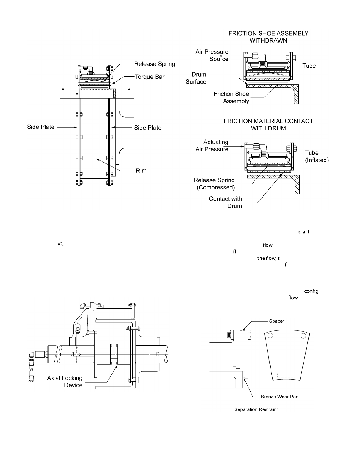
1.2 How It Works
1.2.1 Referring to Figures 1 and 2, the neoprene and cord
actuating tube is contained within a steel rim which is
drilled for mounting to the driving component. As air
pressure is applied to the air actuating tube, the tube
inflates, forcing the friction shoe assemblies uniformly
against the drum, which is attached to the driven com-
ponent. The friction shoe assemblies, which consist of
friction blocks attached to aluminum backing plates,
are guided by torque bars which are secured to side
plates. The torque flow is from the driving shaft,
through the element mounting component (typically
an iron spider), through the rim/side plate structure,
through the torque bars to the backing plates and fric-
tion material, where the torque is transmitted through
the friction couple to the components mounted on the
driven shaft (clutch drum and drum mounting compo-
nent). As actuating air is exhausted, release springs
and centrifugal force assure positive disengagement.
1.2.1.1 In some cases, the spider and element assembly may
be mounted to the driven shaft rather than the driving
shaft. This “reverse-mounted” arrangement is typically
used when retrofitting a mill drive and it is more practi-
cal to drill the pinion shaft for the air supply rather than
the motor shaft In these cases, the operation and
torque flow description is opposite to what is stated
above.
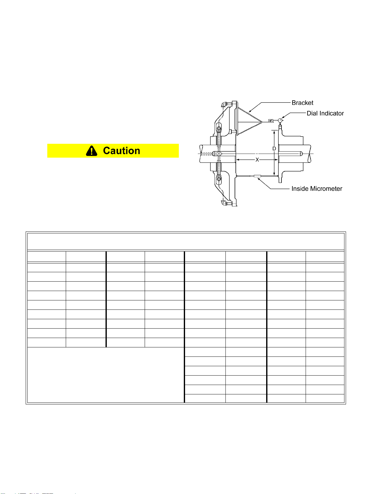
1.2.2 For applications where the clutch is mounted on a
motor shaft having plain bearings, an axial locking
device is used to hold the motor on magnetic center
during operation. Refer to the INSTALLATION
section for axial locking device adjustment.
1.2.2.1 Figure 3A illustrates another type of axial locking
device called a separation restraint. This device is
attached to the clutch rim as shown, with a bronze
wear pad which rides against the clutch drum to
restrict axial movement.
Note : There is no relative motion between the drum
and wear pad when the clutch is fully engaged.