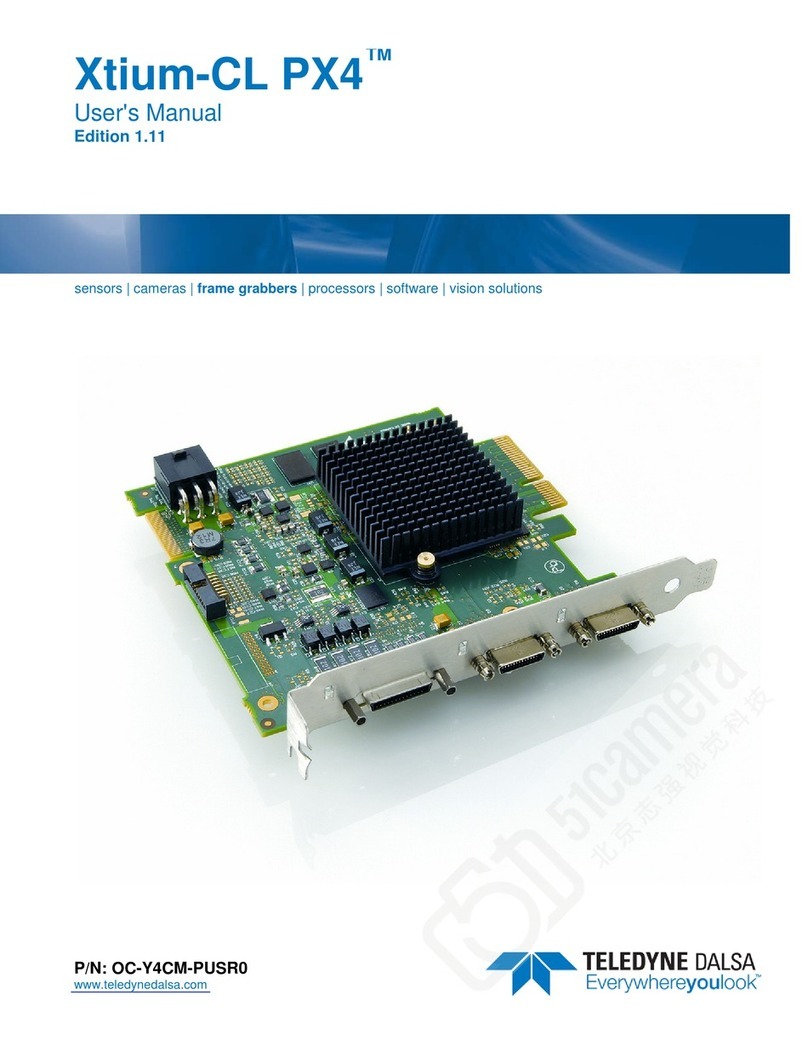
Dalsa X64 Xcelera-CL PX4 User manual

NOTICE
© 2007 DALSA Corp. All rights reserved.
This document may not be reproduced nor transmitted in any form or by any means, either electronic or
mechanical, without the express written permission of DALSA Corp. Every effort is made to ensure the
information in this manual is accurate and reliable. Use of the products described herein is understood to
be at the user’s risk. DALSA Corp. assumes no liability whatsoever for the use of the products detailed in
this document and reserves the right to make changes in specifications at any time and without notice.
Microsoft® is a registered trademark; Windows®, Windows® 2000, Windows® XP, Windows® Vista
are trademarks of Microsoft Corporation.
All other trademarks or intellectual property mentioned herein belong to their respective owners.
Edition 1.10 printed on: April 18, 2007
Document Number: OC-X4CM-PUSR0
Printed in Canada

X64 Xcelera-CL PX4 User's Manual Contents •i
Contents
X64 XCELERA-CL PX4 OVERVIEW________________________________________ 5
PRODUCT PART NUMBERS...................................................................................................5
ABOUT THE X64 XCELERA-CL PX4 FRAME GRABBER ......................................................7
Series Key Features.....................................................................................................7
User Programmable Configurations...........................................................................7
ACUPlus: Acquisition Control Unit............................................................................8
DTE: Intelligent Data Transfer Engine.......................................................................8
Advanced Controls Overview......................................................................................9
ABOUT THE OPTIONAL X-I/O MODULE...............................................................................9
DEVELOPMENT SOFTWARE OVERVIEW .............................................................................10
Sapera++ LT Library................................................................................................10
Sapera Processing Library........................................................................................10
INSTALLING X64 XCELERA-CL PX4______________________________________ 11
WARNING! (GROUNDING INSTRUCTIONS).........................................................................11
UPGRADING SAPERA OR ANY BOARD DRIVER...................................................................11
Board Driver Upgrade Only......................................................................................11
Sapera and Board Driver Upgrades .........................................................................12
SAPERA LT LIBRARY INSTALLATION ................................................................................12
INSTALLING X64 XCELERA-CL PX4 HARDWARE AND DRIVER........................................13
In a Windows 2000/XP/Vista System.........................................................................13
X64 Xcelera-CL PX4 Firmware Loader....................................................................14
ENABLING THE CAMERA LINK SERIAL CONTROL PORT.....................................................16
COM Port Assignment...............................................................................................16
Setup Example with Windows HyperTerminal ..........................................................17
DISPLAYING X64 XCELERA-CL PX4 BOARD INFORMATION ............................................19
Device Manager – Board Viewer..............................................................................19
CAMERA TO CAMERA LINK CONNECTIONS .......................................................................20
CONFIGURING SAPERA ......................................................................................................21
Viewing Installed Sapera Servers..............................................................................21
Increasing Contiguous Memory for Sapera Resources.............................................21
Contiguous Memory for Sapera Messaging..............................................................22
TROUBLESHOOTING INSTALLATION PROBLEMS ................................................................22
Recovering from a Firmware Update Error..............................................................22
Windows Event Viewer..............................................................................................23
Device Manager Program.........................................................................................23

ii •Contents X64 Xcelera-CL PX4 User's Manual
PCI Configuration.....................................................................................................25
Sapera and Hardware Windows Drivers...................................................................26
Log Viewer................................................................................................................26
Windows Device Manager.........................................................................................27
Memory Requirements with Area Scan Acquisitions.................................................27
Symptoms: CamExpert Detects no Boards................................................................28
Symptoms: X64 Xcelera-CL PX4 Does Not Grab.....................................................28
Symptoms: Card grabs black ....................................................................................29
Symptoms: Card acquisition bandwidth is less than expected..................................29
CAMEXPERT QUICK START _____________________________________________31
INTERFACING CAMERAS WITH CAMEXPERT......................................................................31
CamExpert Example with a Monochrome Camera...................................................31
CAMEXPERT DEMONSTRATION AND TEST TOOLS.............................................................33
CAMERA TYPES & FILES APPLICABLE TO THE X64 XCELERA-CL PX4............................33
CamExpert Memory Errors when Loading Camera Configuration Files.................33
Overview of Sapera Acquisition Parameter Files (*.ccf or *.cca/*.cvi)...................34
Camera Interfacing Check List .................................................................................35
USING THE FLAT FIELD CORRECTION TOOL......................................................................36
X64 Xcelera-CL PX4 Flat Field Support ..................................................................36
Flat Field Correction Calibration Procedure...........................................................36
Using Flat Field Correction......................................................................................38
USING THE BAYER FILTER TOOL.......................................................................................38
Bayer Filter White Balance Calibration Procedure..................................................38
Using the Bayer Filter...............................................................................................39
SAPERA DEMO APPLICATIONS __________________________________________41
GRAB DEMO OVERVIEW ...................................................................................................41
Using the Grab Demo ...............................................................................................41
FLAT-FIELD DEMO OVERVIEW..........................................................................................42
Using the Flat Field Demo........................................................................................42
X64 XCELERA-CL PX4 REFERENCE ______________________________________43
FULL BLOCK DIAGRAM.....................................................................................................43
ACQUISITION TIMING ........................................................................................................44
LINE TRIGGER SOURCE SELECTION FOR LINESCAN APPLICATIONS...................................45
CORACQ_PRM_EXT_LINE_TRIGGER_SOURCE – Parameter Values
Specific to the X64-CL series.............................................................................45
SHAFT ENCODER INTERFACE TIMING................................................................................47
VIRTUAL FRAME_RESET FOR LINESCAN CAMERAS ..........................................................48
ACQUISITION METHODS....................................................................................................50
SUPPORTED EVENTS..........................................................................................................50
LUT AVAILABILITY..........................................................................................................52
SUPPORTING NON-STANDARD CAMERALINK CAMERAS...................................................52
Firmware: X64-CL 10-Tap Format 2........................................................................52
X64 XCELERA-CL PX4 SUPPORTED PARAMETERS...........................................................54

X64 Xcelera-CL PX4 User's Manual Contents •iii
Camera Related Capabilities - CameraLink Full Mono............................................54
Camera Related Parameters - CameraLink Full Mono ............................................55
VIC Related Parameters - CameraLink Full Mono...................................................60
ACQ Related Parameters - CameraLink Full Mono .................................................65
Camera Related Capabilities - CameraLink Medium Color RGB ............................65
Camera Related Parameters - CameraLink Medium Color RGB .............................66
VIC Related Parameters - CameraLink Medium Color RGB....................................70
ACQ Related Parameters - CameraLink Medium Color RGB..................................75
MEMORY ERROR WITH AREA SCAN FRAME BUFFER ALLOCATION...................................76
SAPERA SERVERS & RESOURCES _______________________________________ 77
SERVERS AND RESOURCES ................................................................................................77
TRANSFER RESOURCE LOCATIONS ....................................................................................78
TECHNICAL SPECIFICATIONS __________________________________________ 79
X64 XCELERA-CL PX4 BOARD SPECIFICATIONS .............................................................79
HOST SYSTEM REQUIREMENTS .........................................................................................81
EMI CERTIFICATIONS .......................................................................................................81
CONNECTOR AND SWITCH LOCATIONS..............................................................................82
X64 Xcelera-CL PX4 Board Layout Drawing...........................................................82
Connector Description List .......................................................................................82
CONNECTOR AND SWITCH SPECIFICATIONS ......................................................................83
X64 Xcelera-CL PX4 End Bracket Detail .................................................................83
Configuration Micro-switches...................................................................................84
Status LEDs Functional Description.........................................................................85
J2: Camera Link Connector 1...................................................................................86
J3: Camera Link Connector 2...................................................................................87
Camera Link Camera Control Signal Overview........................................................88
J4: External Signals Connector.................................................................................89
External Signals Connector Bracket Assembly (Type 1)...........................................94
External Signals Connector Bracket Assembly (Type 2)...........................................97
CAMERA LINK INTERFACE _____________________________________________ 99
CAMERA LINK OVERVIEW.................................................................................................99
Rights and Trademarks..............................................................................................99
DATA PORT SUMMARY....................................................................................................100
CAMERA SIGNAL SUMMARY ...........................................................................................100
CAMERA LINK CABLES ...................................................................................................101
APPENDIX: X-I/O MODULE OPTION_____________________________________ 103
X-I/O MODULE OVERVIEW.............................................................................................103
X-I/O Module Connector List & Locations .............................................................104
X-I/O MODULE INSTALLATION .......................................................................................104
Board Installation....................................................................................................105
X64 Xcelera-CL PX4 and X-I/O Driver Update......................................................105
X-I/O MODULE EXTERNAL CONNECTIONS TO THE DB37...............................................105

iv •Contents X64 Xcelera-CL PX4 User's Manual
DB37 Pinout Description........................................................................................106
TTL Output in NPN Mode: Electrical Details.........................................................107
TTL Output in PNP Mode: Electrical Details.........................................................108
Opto-coupled Input: Electrical Details...................................................................109
TTL Input Electrical Details....................................................................................109
X-I/O MODULE SAPERA INTERFACE ...............................................................................110
Configuring User Defined Power-up I/O States......................................................110
Using Sapera LT General I/O Demo.......................................................................111
Sapera LT General I/O Demo Code Samples..........................................................113
DALSA CONTACT INFORMATION_______________________________________117
SALES INFORMATION ......................................................................................................117
TECHNICAL SUPPORT ......................................................................................................118
GLOSSARY OF TERMS _________________________________________________119
INDEX_________________________________________________________________123

X64 Xcelera-CL PX4 User's Manual X64 Xcelera-CL PX4 Overview •5
X64 Xcelera-CL PX4 Overview
Product Part Numbers
X64 Xcelera-CL PX4 Board
Item Product Number
All models have 85MHz Pixel Clock
X64 Xcelera-CL PX4 Full with 128 MB of memory
X64 Xcelera-CL PX4 Dual with 128 MB of memory
OR-X4C0-XPF00
OR-X4C0-XPD00
X-I/O Module (optional): provides an additional 8 input & 8 output general I/Os
(see "Appendix: X-I/O Module Option" on page 103) OC-IO01-STD00
For OEM clients, this manual in printed form, is available on request OC-X4CM-USER0
X64 Xcelera-CL PX4 Software
Item Product Number
Sapera LT version 6.00 or later (required but sold separately)
1. Sapera LT: Provides everything you will need to build your imaging
application
2. Current Sapera compliant board hardware drivers
3. Board and Sapera documentation (compiled HTML help, and Adobe
Acrobat® (PDF) formats)
OC-SL00-0000000
(optional)
Sapera Processing Imaging Development Library includes over 600 optimized image
processing routines.
Contact Sales at
DALSA

6 •X64 Xcelera-CL PX4 Overview X64 Xcelera-CL PX4 User's Manual
X64 Xcelera-CL PX4 Cables & Accessories
Item Product Number
(optional) X64 Xcelera-CL PX4 can be shipped with an External Signals Connector
Bracket Assembly, either with a DB37 or DB25 connector (see the two product
numbers below). Either cable, if required, should be specified at the time of order.
Note: clients requiring more I/O connections must add the optional X-I/O Module.
DB37 assembly
see "External Signals Connector Bracket Assembly (Type 1)"on page 94.
This cable assembly connects to J4.
OR-X4CC-IOCAB
DB25 assembly
see "External Signals Connector Bracket Assembly (Type 2)"on page 97.
Provides direct compatibility with external cables made for products such as the
X64-CL iPro. This cable assembly connects to J4.
OR-X4CC-0TIO2
(optional) Power interface cable required when supplying power to cameras OC-COMC-PCPWR
(optional) Camera Link Video Input Cable:
1meter
2meter
OC-COMC-CLNK0
OC-COMC-CLNK6

X64 Xcelera-CL PX4 User's Manual X64 Xcelera-CL PX4 Overview •7
About the X64 Xcelera-CL PX4 Frame Grabber
Series Key Features
• Monochrome or RGB Camera Link
• Flat Field Correction
• Bayer Filter Decoding
• Output lookup tables available for each mode
• Vertical Flip supported on board
• RoHS compliant
See “Technical Specifications” on page 79 for detailed information.
User Programmable Configurations
Use the X64 Xcelera-CL PX4 firmware loader function in the DALSA Device manager utility to select
firmware for one of the supported modes. Firmware selection is made either during driver installation or
manually later on (see "Firmware Update: Manual Mode"on page 14).
For the X64 Xcelera-CL PX4 Full board the firmware choices are:
• Full Camera Link Input withFlat Field Correction (installation default selection)
Support for one Base or one Medium or one Full Camera Link port. Flat Field Correction (FFC)
includes Fixed Pattern Noise (FPN), Pixel Replacement, Photo Response Non Uniformity (PRNU),
and Shading Correction.
• Base Camera Link Input with Bayer Filter Decoding.
• Camera Link Input with 10 Tap Format 2 support with Flat Field Correction
Supports camera such as the Basler A504. See "Supporting Non-Standard CameraLink Cameras" on
page 52 for details.
For the X64 Xcelera-CL PX4 Dual board the firmware choices are:
• Dual Base Camera Link Input withFlat Field Correction (installation default selection)
Support for one or two Base Camera Link ports. Flat Field Correction (FFC) includes Fixed Pattern
Noise (FPN), Pixel Replacement, Photo Response Non Uniformity (PRNU), and Shading Correction.
• Dual Base Camera Link Input with Bayer Filter Decoding.
• One Medium Camera Link Input with Flat field correction.

8 •X64 Xcelera-CL PX4 Overview X64 Xcelera-CL PX4 User's Manual
ACUPlus:Acquisition Control Unit
ACUPlus consists of a grab controller, one pixel packer, and one time base generator. ACUPlus delivers a
flexible acquisition front end plus it supports pixel clock rates of up to 85MHz.
ACUPlus acquires variable frame sizes up to 256KB per horizontal line and up to 16 million lines per
frame. ACUPlus can also capture an infinite number of lines from a linescan camera without losing a
single line of data.
ACUPlus supports standard Camera Link multi-tap configurations from 8 to 64-bit/pixels. Additionally,
alternate tap configurations can support up to 8 taps of 8-bits each or optionally 10 tap with alternate
firmware.
DTE: Intelligent Data Transfer Engine
The X64 Xcelera-CL PX4 intelligent Data Transfer Engine ensures fast image data transfers between the
board and the host computer with zero CPU usage. The DTE provides a high degree of data integrity
during continuous image acquisition in a non-real time operating system like Windows. DTE consists of
multiple independent DMA units, Tap Descriptor Tables, and Auto-loading Scatter-Gather tables.
PCI Express x4 Interface
The X64 Xcelera-CL PX4 is a universal PCI Express x4 board, compliant with the PCI Express 1.0a
specification. The X64 Xcelera-CL PX4 board achieves transfer rates up to 680 Mbytes/sec. with all taps
used when connected to a corresponding camera or sensor.
The X64 Xcelera-CL PX4 board occupies one PCI Express x4 expansion slot and one chassis opening
(two slots with the optional X-I/O Module Option).
Important:
• Older computers may not support the maximum data transfer bandwidth defined for PCI Express x4.
• The X64 Xcelera-CL PX4 board can also be used in an PCI Express x8 slot typically without issue.
• If the computer only has a PCI Express x16 slot, direct installation tests or the computer
documentation is required to know if the X64 Xcelera-CL PX4 is supported. It has been seen that
many computer motherboards only support x16 products in x16 slots (commonly used with graphic
video boards).

X64 Xcelera-CL PX4 User's Manual X64 Xcelera-CL PX4 Overview •9
Advanced Controls Overview
Visual Indicators
X64 Xcelera-CL PX4 features a LED indicator to facilitate system installation and setup. This provides
visual feedback indicating when the camera is connected properly and sending data.
External Event Synchronization
Trigger inputs and strobe signals are provided to precisely synchronize image captures with external
events.
Camera Link Communications ports
Two PC independent communication ports provide Camera Link controls for camera configurations.
These ports do not require addition PC resources like free interrupts or I/O address space. Accessible via
the board device driver, the communication ports present a seamless interface to Windows-based standard
communication applications like HyperTerminal, etc. The communication ports are accessible directly
from the Camera Link connectors.
Quadrature Shaft Encoder
An important feature for web scanning applications, the Quadrature-Shaft-Encoder inputs allow
synchronized line captures from external web encoders.
About the Optional X-I/O Module
The optional X-I/O module adds independent general purpose software controllable I/O signals to the
X64 Xcelera-CL PX4. The X-I/O module provides 2 opto-coupled inputs, 6 logic signal inputs (5V or
24V), and 8 TTL outputs (NPN or PNP type selectable). The module also makes available 5V or 12V dc
power from the host system.
The X-I/O module can be either purchased with the X64 Xcelera-CL PX4 board or installed into the
computer system at a later time. The module occupies one adjacent PCI slot and connects to the X64
Xcelera-CL PX4 via a ribbon cable. X-I/O Module external connections are made via the DB37
connector on the module bracket.
X-I/O requires X64 Xcelera-CL PX4 board driver version 1.00 or later and Sapera LT version 6.0 or
later.
See "Appendix: X-I/O Module Option" on page 103 for details and specifications.

10 •X64 Xcelera-CL PX4 Overview X64 Xcelera-CL PX4 User's Manual
Development Software Overview
Sapera++ LT Library
Sapera++ LT is a powerful development library for image acquisition and control. Sapera++ LT provides
a single API across all current and future DALSA hardware. Sapera++ LT delivers a comprehensive
feature set including program portability, versatile camera controls, flexible display functionality and
management, plus easy to use application development wizards.
Sapera++ LT comes bundled with CamExpert, an easy to use camera configuration utility to create new,
or modify existing camera configuration files.
Sapera Processing Library
Sapera Processing is a comprehensive set of C++ classes for image processing and analysis. Sapera
Processing offers highly optimized tools for image processing, blob analysis, search (pattern recognition),
OCR and barcode decoding.

X64 Xcelera-CL PX4 User's Manual Installing X64 Xcelera-CL PX4 •11
Installing X64 Xcelera-CL PX4
Warning! (Grounding Instructions)
Static electricity can damage electronic components. Please discharge any static electrical charge by
touching a grounded surface, such as the metal computer chassis, before performing any hardware
installation.
If you do not feel comfortable performing the installation, please consult a qualified computer technician.
Never remove or install any hardware component with the computer power on.
Upgrading Sapera or any Board Driver
When installing a new version of Sapera or a DALSA acquisition board driver in a computer with a
previous installation, the current version must be un-installed first. Upgrade scenarios are described
below.
Board Driver Upgrade Only
Minor upgrades to acquisition board drivers are typically distributed as ZIP files available in the DALSA
web site http://www.imaging.com/downloads. Board driver revisions are also available on the next
release of the Sapera CD-ROM.
Often minor board driver upgrades do not require a new revision of Sapera. To confirm that the current
Sapera version will work with the new board driver:
• Check the new board driver ReadMe.txt file before installing, for information on the minimum
Sapera version required.
• If the ReadMe.txt file does not specify the Sapera version, contact DALSA Technical Support
(see "Technical Support" on page 118 ).
To upgrade the board driver only:
• Logon the computer as an administrator or with an account that has administrator privileges.
• From the Windows start menu select Start • Programs • DALSA • X64 Xcelera-CL PX4
Driver • Modify-Repair-Remove.
• Click on Remove.
• When the driver un-install is complete, reboot the computer.
• Logon the computer as an administrator again.

12 •Installing X64 Xcelera-CL PX4 X64 Xcelera-CL PX4 User's Manual
• Install the new board driver. Run Setup.exe if installing manually from a downloaded driver file.
• If the new driver is on a Sapera CD-ROM follow the installation procedure described in
"Installing X64 Xcelera-CL PX4 Hardware and Driver" on page 13.
• Note that you can not install a DALSA board driver without Sapera LT installed on the
computer.
Sapera and Board Driver Upgrades
When both Sapera and the acquisition board driver are upgraded, follow the procedure described below.
• Logon the computer as an administrator or with an account that has administrator privileges.
• From the Windows start menu select Start • Programs • DALSA • X64 Xcelera-CL PX4
Driver • Modify-Repair-Remove.
• Click on Remove to uninstall the board driver.
• From the Windows start menu select Start • Programs • DALSA • Sapera LT • Modify-
Repair-Remove.
• Click on Remove to uninstall Sapera.
• Reboot the computer and logon the computer as an administrator again.
• Install the new versions of Sapera and the board driver as if this was a first time installation. See
"Sapera LT Library Installation"on page 12 and "Installing X64 Xcelera-CL PX4 Hardware and
Driver" on page 13 for installation procedures.
Sapera LT Library Installation
Note: to install Sapera LT and the X64 Xcelera-CL PX4 device driver, logon to the workstation as
administrator or with an account that has administrator privileges.
The Sapera LT Development Library (or ‘runtime library’ if application execution without development
is preferred) must be installed before the X64-CL device driver.
• Insert the DALSA Sapera CD-ROM. If AUTORUN is enabled on your computer, the
installation menu is presented.
• If AUTORUN is not enabled, use Windows Explorer and browse to the root directory of the
CD-ROM. Execute launch.exe to start the installation menu and install the required Sapera
components.
• The installation program will prompt you to reboot the computer.
Refer to Sapera LT User’s Manual for additional details about Sapera LT.

X64 Xcelera-CL PX4 User's Manual Installing X64 Xcelera-CL PX4 •13
Installing X64 Xcelera-CL PX4 Hardware and
Driver
In a Windows 2000/XP/Vista System
• Turn the computer off and open the computer chassis to allow access to the expansion slot area.
• Install the X64 Xcelera-CL PX4 into a free PCI Express x4 expansion slot. The X64 Xcelera-CL
PX4 could also be installed in a PCI Express x8. Note that some computer's x16 slot may
support the X64 Xcelera-CL PX4. The user needs to test each computer to verify support of a x4
product.
• Close the computer chassis and turn the computer on. Driver installation requires administrator
rights for the current user of the computer.
• Windows will find the X64 Xcelera-CL PX4 and start its Found New Hardware Wizard. Click
on the Cancel button to close the Wizard.
• Insert the DALSA Sapera CD-ROM. If AUTORUN is enabled on your computer, the
installation menu is presented. Install the X64 Xcelera-CL PX4 driver.
• If AUTORUN is not enabled, use Windows Explorer and browse to the root directory of the
CD-ROM. Execute launch.exe to start the installation menu and install the X64 Xcelera-CL
PX4 driver.
• Reboot the computer when prompted. During the early stages of the Windows reboot, the X64
Xcelera-CL PX4 firmware loader application starts. This is described in detail in the following
section. Allow Windows to complete its reboot before proceeding.
• When using Windows 2000, if the Digital Signature Not Found message is displayed, click on
Yes to continue the X64 Xcelera-CL PX4 driver installation. Reboot the computer when
prompted.
• When using Windows XP, if a message stating that the X64 Xcelera-CL PX4 software has not
passed Windows Logo testing is displayed, click on Continue Anyway to finish the X64
Xcelera-CL PX4 driver installation. Reboot the computer when prompted.
• When using Windows Vista, a message stating that Windows can not verify the publisher of the
driver software is displayed. Click on Install this driver software anyway.

14 •Installing X64 Xcelera-CL PX4 X64 Xcelera-CL PX4 User's Manual
X64 Xcelera-CL PX4 Firmware Loader
After Windows boots, the Device Manager-Firmware Loader program automatically executes. It will
determine if the X64 Xcelera-CL PX4 requires a firmware update. If firmware is required, the dialog
displays and it also allows the user to load firmware for alternate operational modes of the X64 Xcelera-
CL PX4.
Important:In the vary rare case of firmware loader errors please see "Recovering from a Firmware
Update Error" on page 22.
Firmware Update: Automatic Mode
Click Automatic to update the X64 Xcelera-CL PX4 firmware. The X64 Xcelera-CL PX4 Full supports
three firmware configurations with the default being a Full, Medium, or Base camera with Flat Field
correction.
The X64 Xcelera-CL PX4 Dual board supports three firmware configurations with the default being
dual Base cameras with Flat Field correction.
See “Series Key Features”on page 7 and “User Programmable Configurations” on page 7 for details on
all supported modes, which can be selected via a manual firmware update.
If there are multiple X64 Xcelera-CL PX4 boards in the system, all will be updated with new firmware. If
any installed X64 Xcelera-CL PX4 board installed in a system already has the correct firmware version,
an update is not required. In the following screen shot, a single X64 Xcelera-CL PX4 Full board is
installed in the system and the default configuration is ready to be programmed.
Firmware Update: Manual Mode
Select Manual mode to load firmware other then the default version or when, in the case of multiple X64
Xcelera-CL PX4 boards in the same system, each requires different firmware.
The figure below shows the Device Manager manual firmware screen. Information on all installed X64
Xcelera-CL PX4 boards, their serial numbers, and their firmware components are shown.

X64 Xcelera-CL PX4 User's Manual Installing X64 Xcelera-CL PX4 •15
A manual firmware update is made as follows:
• Select the X64 Xcelera-CL PX4 to update via the board selection box (if there are multiple
boards in the system)
• From the Configuration field drop menu select the firmware version required
• Click on the Start Update button
• Observe the firmware update progress in the message output window
• Close the Device manager program when the device reset complete message is shown.
Executing the Firmware Loader from the Start Menu
If required, the X64-CL Firmware Loader program is executed via the Windows Start Menu shortcut
Start • Programs • DALSA • X64 Xcelera-CL PX4 Driver • Firmware Update. A firmware change
after installation would be required to select a different Camera Link configuration mode. See "User
Programmable Configurations" on page 7.

16 •Installing X64 Xcelera-CL PX4 X64 Xcelera-CL PX4 User's Manual
Enabling the Camera Link Serial Control Port
The Camera Link cabling specification includes a serial communication port for direct camera control by
the frame grabber (see "J2: Camera Link Connector 1 " on page 86). The X64 Xcelera-CL PX4 driver
supports this serial communication port either directly or by mapping it to a host computer COM port.
Any serial port communication program, such as Windows HyperTerminal, can connect to the camera in
use and modify its function modes via its serial port controls. The X64 Xcelera-CL PX4 serial port
supports communication speeds from 9600 to 115 kbps.
Note: if your serial communication program can directly select the X64 Xcelera-CL PX4 serial port then
mapping to a system COM port is not necessary.
The X64 Xcelera-CL PX4 serial port is mapped to an available COM port by using the Sapera
Configuration tool. Run the program from the Windows start menu: Start • Programs • DALSA •
Sapera LT • Sapera Configuration.
COM Port Assignment
The lower section of the Sapera Configuration program screen contains the serial port configuration
menu. Configure as follows:
• Use the Physical Port drop menu to select the Sapera board device from all available Sapera
boards with serial ports (when more then one board is in the system).
• Use the Maps to drop menu to assign an available COM number to that Sapera board serial port.
• Click on the Save Settings Now button then the Close button. You are prompted to reboot your
computer to enable the serial port mapping.
• The X64 Xcelera-CL PX4 serial port, now mapped to COM3 in this example, is available as a
serial port to any serial port application for camera control. Note that this serial port is not listed
in the Windows Control Panel•System Properties•Device Manager because it is a logical
serial port mapping.
• An example setup using Windows HyperTerminal follows.

X64 Xcelera-CL PX4 User's Manual Installing X64 Xcelera-CL PX4 •17
Setup Example with Windows HyperTerminal
• Run HyperTerminal and type a name for the new connection when prompted. Then click OK.
• On the following dialog screen select the port to connect with. The port could be the COM port
mapped to the X64 Xcelera-CL PX4 or the COM device as shown in this example.

18 •Installing X64 Xcelera-CL PX4 X64 Xcelera-CL PX4 User's Manual
• HyperTerminal now presents a dialog to configure the COM port properties. Change settings as
required by the camera you are connecting to. Note that the X64 Xcelera-CL PX4 serial port
does not support hardware flow control.
Table of contents
Other Dalsa Media Converter manuals