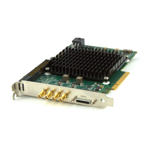
Dalsa PC2-CamLink User manual

DALSA •7075 Place Robert-Joncas, Suite 142 •Montreal, Quebec, Canada •H4M 2Z2
http://www.dalsa.com/mv
*OC-PC2M-CUM00*
PC2-CamLink
User's Manual
Part number OC-PC2M-CUM00
Edition 2.32

NOTICE
© 2001-2010 DALSA Corp. All rights reserved.
This document may not be reproduced nor transmitted in any form or by any means, either electronic
or mechanical, without the express written permission of DALSA Corp. Every effort is made to ensure
the information in this manual is accurate and reliable. Use of the products described herein is
understood to be at the user's risk. DALSA Corp. assumes no liability whatsoever for the use of the
products detailed in this document and reserves the right to make changes in specifications at any time
and without notice.
Microsoft is a registered trademark; Windows®, Windows® XP, Windows® Vista, and Windows® 7
are trademarks of Microsoft® Corporation.
All other trademarks or intellectual property mentioned herein belong to their respective owners.
Manual revision: June 15, 2010
Document Number: OC-PC2M-CUM00
Printed in Canada

PC2-CamLink User's Manual Contents •i
Contents
INTRODUCTION................................................................................................................... 1
OVERVIEW OF THE MANUAL ........................................................................................ 1
About the Manual ......................................................................................... 2
Using the Manual ......................................................................................... 2
PART I: PC2-CAMLINK BOARD ....................................................................................... 3
THE PC2-CAMLINK ..................................................................................................... 5
Components & Part Numbers....................................................................... 5
EC & FCC Certificate of Conformity ........................................................... 6
PC2-CAMLINK–INSTALLATION OVERVIEW ................................................................. 7
Warning! (Grounding Instructions).............................................................. 7
Before Installing ........................................................................................... 7
Configuration Jumpers ................................................................................. 7
SAPERA LT LIBRARY INSTALLATION........................................................................... 8
INSTALLING PC2-CAMLINK HARDWARE AND DRIVER ................................................ 8
In a Windows XP, Windows Vista, or Windows 7 System ............................ 8
UPGRADING SAPERA OR ANY BOARD DRIVER ............................................................. 9
Board Driver Upgrade Only......................................................................... 9
Sapera and Board Driver Upgrades........................................................... 10
COM Port Assignment................................................................................ 10
Configuring Sapera .................................................................................... 12
IFC SOFTWARE INSTALLATION.................................................................................. 15
IFC-SDK™ ................................................................................................. 15
Configuring Serial Port Under IFC............................................................ 17
Upgrading Onboard Firmware .................................................................. 20
THEORY OF OPERATION ............................................................................................. 21
PC2-CamLink Flow Diagram..................................................................... 21
Camera Control and Synchronization ........................................................ 23
Camera Interface ........................................................................................ 42
Input LUT ................................................................................................... 43
Data Port Sequencer................................................................................... 44
Window Generator...................................................................................... 47
YCrCb Engine............................................................................................. 48
PCI Controller ............................................................................................ 49
Visual Status LEDs ..................................................................................... 52
Parallel I/O................................................................................................. 53

ii •Contents PC2-CamLink User's Manual
Acquisition Interrupts ................................................................................. 55
Error Support Interrupts............................................................................. 59
Camera Power ............................................................................................ 60
Trigger-to-Image Reliability....................................................................... 60
TECHNICAL REFERENCE............................................................................................. 64
Block Diagram............................................................................................ 64
Hardware Specifications............................................................................. 65
PC2-CamLink Connector and Jumper Locations....................................... 67
Computer Requirements for the PC2-CamLink .......................................... 75
CAMERA LINK™ INTERFACE ..................................................................................... 76
Camera Link™ Overview ........................................................................... 76
Data Port Summary .................................................................................... 77
Camera Signal Summary ............................................................................ 77
Camera Link™ Cables................................................................................ 78
PART II: SAPERA LT ......................................................................................................... 81
SAPERA SERVER AND PARAMETERS ........................................................................... 83
SAPERA SOFTWARE EXAMPLE.................................................................................... 93
Grab Demo Overview ................................................................................. 93
Using the Grab Demo ................................................................................. 94
Using Sapera CamExpert with PC2-CamLink............................................ 97
PART III: IFC ..................................................................................................................... 101
IFC SOFTWARE EXAMPLES ...................................................................................... 103
IFC Examples for PC2-CamLink.............................................................. 103
PC-CAMLINK IFC PARAMETERS COMPARISON ....................................................... 105
Overview ................................................................................................... 105
PART IV: TROUBLESHOOTING AND SUPPORT ...................................................... 113
TROUBLESHOOTING ................................................................................................. 115
Overview ................................................................................................... 115
Tools.......................................................................................................... 115
Symptoms .................................................................................................. 117
DALSA CONTACT INFORMATION............................................................................ 121
Sales Information...................................................................................... 121
TECHNICAL SUPPORT ............................................................................................... 122
GLOSSARY OF TERMS ................................................................................................... 123
INDEX .................................................................................................................................. 127

PC2-CamLink User's Manual Introduction •1
Introduction
Overview of the Manual
• Part I: PC2-CamLink Board
• The PC2-CamLink
Description of the PC2-CamLink board and its software as well as PC2-CamLink
package contents list.
Installing the PC2-CamLink
Hardware installation instructions as well as information concerning jumper
configuration and connecting cameras and devices.
Sapera LT Software Installation
Illustrates how to install Sapera LT and the PC2-CamLink device driver as well as
information concerning COM Port assignment and how to configure Sapera LT.
IFC Software Installation
Illustrates how to install IFC as well as information concerning upgrading onboard
firmware, configuring the serial port, and starting Camera Configurator.
Theory of Operation
Detailing PC2-CamLink features.
Technical Reference
PC2-CamLink specifications. Includes connector and pinout diagrams.
Camera Link™ Interface
Information concerning the Camera Link™ specification.
• Part II: Sapera LT
• Sapera Server and Parameters
Lists the Sapera server available and describes the Sapera parameters and values
supported by PC2-CamLink.
Sapera Software Examples
Describes in detail the Sapera Grab Demo.
• Part III: IFC
• IFC Software Examples
Two board specific examples of IFC software features using the PC2-CamLink.
PC-CamLink IFC Parameters Comparison
Lists PC-CamLink parameters compared with their corresponding PC2-CamLink
parameters.
• Part IV: Troubleshooting and Support
• Troubleshooting
Offers suggestions for resolving installation or usage problems.

2 •Introduction PC2-CamLink User's Manual
DALSA Contact Information
Phone numbers, web sites, and important email addresses.
About the Manual
This manual exists in Adobe Acrobat (PDF) format. The PDF format makes full use of hypertext
cross-references and include links to the DALSA home page on the Internet located at
http://www.dalsa.com/mv, accessed using any web browser.
Using the Manual
File names, directories, and Internet sites will be in bold text
(e.g., image2.bmp, c:\IFC, http://www.dalsa.com).
Text that must be entered using the keyboard will be in typewriter-style text
(e.g., c:\temp).
Menu and dialog actions will be indicated in bold text in the order of the instructions to be executed,
with each instruction separated by bullets. For example, going to the File menu and choosing Save
would be written as File•Save.

PC2-CamLink User's Manual Part I: PC2-CamLink Board •3
Part I: PC2-CamLink Board

4 •Part I: PC2-CamLink Board PC2-CamLink User's Manual

PC2-CamLink User's Manual Part I: PC2-CamLink Board •5
The PC2-CamLink
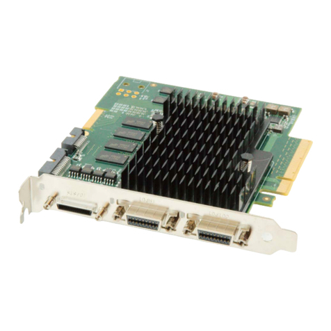
The PC2-CamLink is a half slot frame grabber that grabs images from a single base digital Camera
Link™ camera to host memory for processing. The board was designed for cost-effective
performance. Both linescan and area scan cameras are supported. Up to two channels are supported.
Note that RGB is not supported.
Components & Part Numbers
The following table lists the components and part numbers for the PC2-CamLink:
Item Part Number
Board
PC2-CamLink OC-PC20-C0000
Cables & Accessories
Camera Link™ Video Input Cable (optional product):
1 meter OC-COMC-CLNK0
2 meter OC-COMC-CLNK6
Optional Cable
Floppy power connector* (connects to J14) OC-COMC-POW03
Parallel I/O connector to female D-sub 25 bracket assembly (connects to J8) 4816
Documentation
PC2-CamLink User’s manual OC-PC2M-CUM00
IFC-SDK Software manual 403-00004-00
Camera Configurator® User's manual 405-00006-00
*The floppy power connector can be ordered by contacting DALSA. See “DALSA Contact
Information”(on page 121) for further information.

6 •Part I: PC2-CamLink Board PC2-CamLink User's Manual
EC & FCC Certificate of Conformity

PC2-CamLink User's Manual Part I: PC2-CamLink Board •7
PC2-CamLink–Installation Overview
Warning! (Grounding Instructions)
Static electricity can damage electronic components. Please discharge any static electrical charge by
touching a grounded surface, such as the metal computer chassis, before performing any hardware
installation.
If you do not feel comfortable performing the installation, consult a qualified computer technician.
Never remove or install any hardware component with the computer power on. Disconnect the
power cord from the computer to disable the power standby mode. This prevents the case where
some computers unexpectedly power up when a board is installed.
Before Installing
Make certain that a free PCI expansion slot is available PC2-CamLink is compatible with either 5V or
3.3V PCI slots..
Confirm that you are using Windows XP, Windows Vista, or Windows 7. Other versions of Windows
or non-Microsoft operating systems are not supported.
Configuration Jumpers
PC2-CamLink is equipped with two type of jumpers:
• Opto-coupler jumper
• Camera power jumper
The opto-coupler jumper includes four connectors divided into two sets of two: opto1 (J5 and J6) and
opto2 (J3 and J4). This jumper selects specific voltage power to the opto-coupler by means of jumper
configuration. See “J3, J4, J5, J6: Opto-coupler Voltage Selector”(on page 70) for more information.
Factory default is 0-6V for TTL voltage level connections.
The camera power jumper, J13, controls camera power on the DB-15 connector by means of jumper
configuration. For important information concerning this topic, see the “Camera Power”section (on
page 60). Factory default is no voltage.

8 •Part I: PC2-CamLink Board PC2-CamLink User's Manual
Sapera LT Library Installation
Note: to install Sapera LT and the PC2-CamLink device driver, logon to the workstation as an
administrator or with an account that has administrator privileges.
The Sapera LT Development Library (or ‘runtime library’ if application execution without
development is preferred) must be installed before the PC2-CamLink device driver.
• Insert the DALSA Sapera CD-ROM. If AUTORUN is enabled on your computer, the DALSA
installation menu is presented.
• If AUTORUN is not enabled, use Windows Explorer and browse to the root directory of the CD-
ROM. Execute launch.exe to start the DALSA installation menu and install the required Sapera
components.
• The installation program will prompt you to reboot the computer.
Refer to Sapera LT User’s Manual for additional details about Sapera LT.
Installing PC2-CamLink Hardware and Driver
In a Windows XP, Windows Vista, or Windows 7 System
• Turn the computer off, disconnect the power cord (disables power standby mode), and open the
computer chassis to allow access to the expansion slot area.
• Install the PC2-CamLink into a free PCI slot.
• Close the computer chassis and turn the computer on. Driver installation requires administrator
rights for the current user of the computer.
• Windows will find the PC2-CamLink and start its Found New Hardware Wizard. Click on the
Cancel button to close the Wizard Application.
• Insert the DALSA Sapera CD-ROM. If AUTORUN is enabled on your computer, the DALSA
installation menu is presented. Install the PC2-CamLink driver.
• If AUTORUN is not enabled, use Windows Explorer and browse to the root directory of the CD-
ROM. Execute launch.exe to start the DALSA installation menu and install the PC2-CamLink
driver. Note, if you are using Windows Vista or Windows 7 with the User Account Control
feature enabled, a dialog is displayed when you execute launch.exe; click Allow to continue with
the driver installation.
• Choose the device driver setup type, full installation (required for application development) or
runtime installation (supports application execution only).
• When using Windows XP, if a message stating that the PC2-CamLink software has not passed
Windows Logo testing is displayed, click on Continue Anyway to finish the PC2-CamLink
driver installation. Reboot the computer if prompted to do so.

PC2-CamLink User's Manual Part I: PC2-CamLink Board •9
• When using Windows Vista or Windows 7, a message asking to install the DALSA device
software is displayed. Click Install.
Upgrading Sapera or any Board Driver
When installing a new version of Sapera or a DALSA acquisition board driver in a computer with a
previous installation, the current version must be un-installed first. Upgrade scenarios are described
below.
Board Driver Upgrade Only
Minor upgrades to acquisition board drivers are typically distributed as ZIP files available in the
DALSA web site http://www.dalsa.com/. Board driver revisions are also available on the next release
of the Sapera CD-ROM.
Often minor board driver upgrades do not require a new revision of Sapera. To confirm that the
current Sapera version will work with the new board driver:
• Check the new board driver ReadMe file before installing, for information on the minimum
Sapera version required.
• If the ReadMe file does not specify the Sapera version, contact DALSA Technical Support (see
"Technical Support" on page 122).

10 •Part I: PC2-CamLink Board PC2-CamLink User's Manual
To upgrade the board driver only:
• Logon the computer as an administrator or with an account that has administrator privileges.
• From the Windows start menu select Start • Control Panel • Add or Remove Programs.
• Select the DALSA PC2-CamLink Device Driver, click Remove, and then in the InstallShield
dialog click on Remove to uninstall the board driver.
• When the driver un-install is complete, reboot the computer is prompted to do so.
• Logon the computer as an administrator again.
• Install the new board driver. Run Setup.exe if installing manually from a downloaded driver file.
• Note that you can not install a DALSA board driver without Sapera LT installed on the computer.
Sapera and Board Driver Upgrades
When both Sapera and the acquisition board driver are upgraded, follow the procedure described
below.
• Logon the computer as an administrator or with an account that has administrator privileges.
• From the Windows start menu select Start • Control Panel • Add or Remove Programs.
• Select the DALSA PC2-CamLink Device Driver, click Remove, and then in the InstallShield
dialog click on Remove to uninstall the board driver.
• From the Windows start menu select Start • Control Panel • Add or Remove Programs.
• Select the DALSA Sapera LT program, click Remove, and then in the InstallShield dialog click
on Remove to uninstall Sapera.
• Reboot the computer and logon the computer as an administrator again.
• Install the new versions of Sapera and the board driver as if this was a first time installation. For
installation procedures, see "Sapera LT Library Installation" on page 8 and "Installing PC2-
CamLink Hardware and Driver" on page 8 for installation procedures.
COM Port Assignment
The lower section of the Sapera Configuration program screen contains the serial port configuration
menu. Configure as follows:
• Open the ‘Sapera Configuration’ program (Start•Programs•DALSA•Sapera LT•Sapera
Configuration).
• Use the Physical Port drop menu to select the Sapera board device from all available Sapera
boards using serial ports (when more then one board is in your system).
• Use the Maps to drop menu to assign an available COM number to the Sapera board serial port.
• Click on the Save Settings Now button and then the Close button. You are prompted to reboot
your computer to enable serial port mapping.

PC2-CamLink User's Manual Part I: PC2-CamLink Board •11
• The PC2-CamLink serial port (mapped to COM3 in this example) is available as a serial port to
any serial port application for camera control. Note that this serial port is not listed in the
Windows•Control Panel•System Properties•Device Manager because it is a logical serial port
mapping.

12 •Part I: PC2-CamLink Board PC2-CamLink User's Manual
Configuring Sapera
The Sapera Configuration program (Start•Programs•DALSA•Sapera LT•Sapera Configuration)
allows the user to see all available Sapera servers for the installed Sapera-compatible boards.
Viewing Installed Sapera Servers
The System entry represents the system server. It corresponds to the host machine (your computer)
and is the only server that should be present at all times. As shown in the following screen shoot,
server index 1 is the PC2-CamLink board installed. If required, update the server list by clicking the
Refresh button.

PC2-CamLink User's Manual Part I: PC2-CamLink Board •13
Increasing Contiguous Memory for Sapera Resources
The Contiguous Memory section lets the user specify the total amount of contiguous memory (a
block of physical memory occupying consecutive addresses) reserved for the resources needed for
Sapera buffer allocation and Sapera messaging. For both items, the Requested value dialog box
shows the default driver memory setting while the Allocated value displays the amount of contiguous
memory that has been allocated successfully. The default values will generally satisfy the needs of
most applications.
The Sapera buffer values determine the total amount of contiguous memory reserved at boot time for
the allocation of dynamic resources used for host frame buffer management, such as DMA descriptor
tables as well as other kernel needs. Adjust this value higher if your application generates any out-of-
memory error while allocating host frame buffers. You can approximate the amount of contiguous
memory required as follows:
• Calculate the total amount of host memory used for frame buffers
( number of frame buffers • number of pixels per line • number of lines • (2 - if buffer
is 10 or 12 bits) ).
• Provide 1MB for every 256MB of host frame buffer memory required.
• Add an additional 1MB if the frame buffers have a short line length, e.g., 1k or less
(increased number of individual frame buffers requires more resources).
• Add an additional 2MB for various static and dynamic Sapera resources.
• Test for any memory error when allocating host buffers. Simply select the Buffer button in the
‘General Options’ section of the “Grab Demo Main Window”(see page 95) of the Sapera Grab
Demo program to open the Buffer window (see “Using the Grab Demo” on page 94) to allocate
the number of host buffers required for your acquisition source. Feel free to test the maximum
host buffer limit possible in your host system—Grab Demo will not crash when the requested
number of host frame buffers cannot be allocated.

14 •Part I: PC2-CamLink Board PC2-CamLink User's Manual
Host Computer Frame Buffer Memory Limitations
When planning a Sapera application and the host frame buffers used, as well as other Sapera memory
resources, do not forget the needs of the Windows operating system memory. Window XP, as an
example, should always have a minimum of 128MB for its own use.
A Sapera application using scatter-gather buffers could consume most of the remaining system
memory. When using frame buffers allocated as a single contiguous memory block, typical limitations
are one third of the total system memory with a maximum limit of approximately 100MB. Click on
Buffer under “General Options” in the “Grab Demo Main Window”(see page 95) to select from a list
of host buffer memory allocation types.
Contiguous Memory for Sapera Messaging
The current value for Sapera messaging determines the total amount of contiguous memory reserved
at boot time for message allocation. This memory space is used to store arguments when a Sapera
function is called. Increase this value if you are using functions with large arguments, such as arrays,
and when experiencing any memory errors.

PC2-CamLink User's Manual Part I: PC2-CamLink Board •15
IFC Software Installation
IFC-SDK™
The IFC (Imaging Foundation Classes) library offers a C++ Application Program Interface (API)
intended for use with DALSA’s PC2-CamLink board.
IFC is packaged within the “Imaging Studio CD-ROM”.
See the IFC-SDK™Software Manual for information concerning IFC.
Information in this manual matches IFC 5.8.
Note that PC2-CamLink is supplied with either Imaging Studio (IFC) or Sapera LT. Follow the
installation instructions that correspond to the software supplied with your board. It is not possible to
install both the Sapera LT and IFC PC2-CamLink driver on the same machine.
• Make certain that all applications are closed before installation.
• Insert the ‘Imaging Studio’ CD-ROM.
• Select on Next after auto-start initiates and the ‘Welcome’ window appears.
• Read the ‘Information’ window and select Next if you are not required to make adjustments to
your system. If adjustments are necessary, select Cancel, then make adjustments and re-install
‘Imaging Studio’ CD-ROM.
• Select Yes after reading the ‘Software License Agreement’.
• Enter your name and company in the ‘User Information’ window and select Next.
• Select Next in the ‘Choose Destination Location’ window if you want the software to install in the
default folder. Select Browse to choose another folder if desired.
• If Browse is selected, select OK in the ‘Choose Folder’ window after path, directory, and
driver selections are made.
• The ‘Setup’ window opens and asks if it can create the destination folder displayed. Select
Yes.
• The ‘Choose Destination Location’ window reappears. Select Next.
• The ‘Setup Type’ window is displayed. DALSA recommends selecting typical installation. Select
Next.

16 •Part I: PC2-CamLink Board PC2-CamLink User's Manual
• The ‘Select Components’ window is displayed (see above screen shot). If you do not see PC2-
CamLink in the list, select Next to display more boards. Check PC2-CamLink and select Next.
Note that only the support, configuration files and examples for the board(s) chosen get copied to
your hard drive.
• The ‘Select Program Folder’ window is displayed. You can either retain the default program
folder or create a new one. Select Next for the installation to begin.
• A window appears asking if you want Acrobat Reader to view and print manuals installed with
the ‘Imaging Studio’ CD-ROM. Select Yes if you do not already have Acrobat Reader installed in
your system.
• Select Yes or No after the window appears asking to view readme files.
• The ‘Service Pack Update Check’ window is displayed. This allows you to check for an IFC
service pack update via the DALSA web site. Note that you need an active Internet connection.
Select Yes if you want to check for an update. It is possible to check later for a service pack
update through a shortcut in the IFC program group.
• The ‘Setup Complete’ window appears and asks whether you want to restart the computer now or
at a later time. Choose desired option and select Finish. Note that the computer must be restarted
for the drivers to take effect.
Table of contents
Other Dalsa Media Converter manuals