manuals.online logo
Brands
  1. Home
  2. •
  3. Brands
  4. •
  5. Harman
  6. •
  7. Media Converter
  8. •
  9. Harman AMX NMX-ENC-N2615-WP User manual

Harman AMX NMX-ENC-N2615-WP User manual

AV FOR AN IT WORLD®
Overview
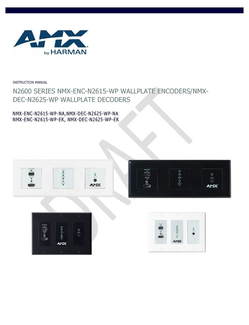
The SVSI NMX-ENC-N2615-WP Encoder Wallplate is part of the N2600 Series and used
in conjunction with N2600 Series Decoders for transmission of video, audio, control, and
USB 2.0 over Ethernet. All Encoders and Decoders of the N2600 Series feature balanced
audio, HDMI video connections, and Power-over-Ethernet (PoE).
Wallplate includes white (WH) and black (BL) faceplate covers.
FIG. 1 N2615-WP WALLPLATE ENCODER
Installing the N2615-WP Wallplate Insert:
Follow the steps below to mount your new N2615-WP Encoder faceplate inserts.
1. Select either the White or Black set of faceplates insert for the wallplate.
2. Locate the faceplate insert alignment tool.
3. Place the alignment tool around the faceplate where the insert will be applied. (Fig.
2)
4. Remove the adhesive from faceplate insert and place the insert within the
alignment tool. (Fig. 2)
•Ensure the LED and IO are aligned with the face insert correctly.
5. Press inserts firmly into place for several seconds before removing alignment tool.
6. Repeat the above process for the remaining faceplate inserts.
FIG. 2 N2615-WP WALLPLATE ENCODER
Installing the N2615-WP Wallplate Encoder:
Follow the steps below to mount your new N2615-WP Encoder into an existing three
gang electrical box. The instructions given assume the box is already installed with
Ethernet access running to it.
1. Connect the PoE-enabled Ethernet cable to the rear connector of the N2615-WP
Encoder. This provides both network and power connection to the Encoder.
2. Place the N2615-WP Encoder into the box and secure it with six screws (included
in shipment).
3. Check LEDs for normal display (see the LED table at right).
4. Attach the (customer-provided US model only) front cover plate to the unit to
complete installation.
Attaching Signal and Control Cables
The following table explains how to attach cables to the front of the Encoder.
IMPORTANT: Encoders must be securely mounted and connected to the switch before
attaching the remaining cables.
NOTE: Any switch handling the N2615-WP Encoder video stream must be configured to
support jumbo frames. Disable the wireless adapter on your computer (it must be hard-
wired to the switch).
QUICK START GUIDE
NMX-ENC-N2615-WP
Basic Cabling Guidelines
Connector Description
HDMI IN
Digital Video Connection
For video encoding of a digital source, connect from the source
to
the Encoder port labeled HDMI IN
using a video cable with an HDMI
connector (or adapter).
DP IN /
USB2.0
Digital Video & USB Data Connection
Attach a USB cable from the PC to the Encoder USB-C port labeled DP IN
/ USB2.0.
AUDIO IN -
STEREO
Audio Encoding
Insert an analog audio cable from the source into the AUDIO IN jack
(optional) or use the embedded audio from the video source.
This table shows LED states on initial power up. If not normal, check connections.
Indicator LEDs
Normal
power up
Indicates
Front-Right LEDs
AUDIO*
Green
Configured to pass analog audio
(coupled with digital or analog video path).
Front-Center LEDs
POWER
Green
PoE power is applied.
STATUS
Green
Flashing (green) when there is software activity.
STREAM
Green
On when the unit is streaming video to the network.
HDCP
Yellow
On when HDCP is active.
LINK/ACT
Green
Flashing when there is Ethernet activity.
Front-Left LEDs
DISPLAY VIDEO*
Green
Configured to pass HDMI with embedded audio.
HDMI VIDEO
Green
On when HDMI sync is detected
* The LEDs for DISPLAY VIDEO and AUDIO each indicate the configured state of the
connectors (not necessarily the presence of signals through the Encoder).
Additional Buttons
The front-center section of the unit is shown in FIG. 3. This section is covered by the
cover plate once it has been installed.
ID button - Identifies the unit in N-Able.
(press and release) Can also set Encoder
back to factory defaults (press and hold 30
seconds).
RESET button - Resets Decoder’s CPU.
FIG. 3 BUTTONS LOCATED ON FRONT OF UNIT BEHIND PLATE COVER
Establishing Connection
N2615-WP Encoders are shipped with DHCP as their default IP mode. The IP address is
assigned automatically based on the network DHCP server. If no DHCP server is found,
the unit will use Auto IP mode instead (with a default IP address of 169.254.xxx.xxx).
Before using your N2615-WP Encoder unit, it must be configured using the free N-Able
device management software. However, you will not be able to configure units until
they are in the same subnet as the host computer. The sample steps below show how
the required changes (to the host computer’s IP settings) are made in a Windows
environment.
30
▪Steps for IP address configuration:
1. From the Control Panel > Network and Internet dialog box, select Network
and Sharing Center.
2. Select Change adapter settings.
3. Select the wired interface connected to your AV network.
4. Click the Properties button.
5. Scroll down in the list to the Internet Protocol Version 4 (TCP/IPv4) option.
Highlight it and click the Properties button.
6. Enable the Use the following IP address option and enter the static IP address
provided to you by your network administrator.
NOTE: If the computer does not need Internet access, you can enter a unique
169.254.xxx.xxx IP address with a 255.255.0.0 Subnet mask. Please contact your
network administrator if you are unsure of how to configure the existing interface. If
the computer has a statically assigned IP address, click on the Advanced button. Then
click Add to enter a unique 169.254.xxx.xxx address with a subnet of 255.255.0.0.
▪Steps for auto discovering devices on the network:
1. Use the host computer to download and install the latest version of N-Able:
1.
PC version - http://www.amx.com/products/N-ABLE-PC.asp
2. Attach your N2615-WP Encoder unit(s) to the managed network switch.
3. Connect the host computer to the same managed network switch.
4. Open the N-Able application.
Note: If all devices do not appear automatically, click the Auto Discover button on
the Unit Management tab. This issues a broadcast command that will discover all
units.
▪Logging in Using N-Able Software
Once the host IP address is configured properly, you can view all discovered units
using the N-Able software. Access the N2615-WP Encoder units from the following
tabs:
•Unit Management tab - N2600 Encoder/Decoder is listed in the Type field.
•Video Matrix tab - N2615-WP Encoder units are found on the N2600 sub-tab
of this screen.
Double-click the unit’s name (in one of the lists mentioned above) to view its
Settings page. If prompted, enter admin and password for the default username and
password. Once logged in, you can change the username and password (using the
options on the unit’s Settings page). From this page, you can access any of the main
pages of the unit’s GUI.
NOTE: If you would like for N-Able to support auto-login to your units, make sure
N-Able’s Device Auto-login settings match the unit’s username and password (by
selecting N-Able > Settings from the N-Able tool bar).
NOTE: N2615-WP Encoder units can be configured to force HTTPS connections, so
your web browser may give you a security warning. N-Able on Windows will ask you
to download OpenSSL for Windows to connect HTTPS.
Basic USB 2.0 Setup
The N2615-WP Wallplate Encoders and N2625-WP/N2622D Decoders are USB
2.0-capable. By default, USB connections are enabled and configured to follow video
switching. Follow these steps for basic USB 2.0 setup.
1. On the N2615-WP Wallplate Encoder, connect the USB-C port to the computer
to be controlled.
2.
Connect the computer’s video output to the Encoder’s
HDMI IN
port.
3. On the N2622D or N2625-WP Decoder, connect the HDMI OUT to the display.
4. Connect a USB 2.0 device to the Decoder’s USB Standard-A ports (they should
be plugged into the top port).
5. Using N-Able, click the Unit Management tab.
6. Click the Auto Discover button to discover your new devices (if you have not
already done so).
7. Once discovery is complete (and you see the new units listed in N-Able), click
the Video Matrix tab.
8. On the matrix, click the common cell for the desired Encoder/Decoder
streaming combination. See the screen shot below for an example.
9. Click the Take button to make the change to your matrix. The radio button
turns green to indicate the connection was successful.
FIG.4 CREATING STREAMING COMBINATIONS
Video/USB Switching Options
Switching
Option
Description
USB Follows Video
By default, units can be switched using N-Able without
modifying the configuration. When you switch video streams
(using the matrix as shown above) the USB functionality will
follow the video.
Independent USB
Switching
Use N-Able’s USB Matrix tab to switch USB control (without
affecting video).
Independent Video
Switching
10. To switch video streams
without
affecting USB control,
first select N-Able > Settings from N-Able’s main menu.
When the N-Able Settings dialog box is displayed,
disable the USB follows Video switching for KVM
units. Now you can use the Video Matrix to switch
video streams only.
Specifications
Product Specifications
Models
Available: NMX-ENC-N2612-WP-NA (US Style)
NMX-ENC-N2612-WP-EK (EU / UK Style)
Power
Requirements:
Powered via a PoE switch or other equipment with a PoE source.
Conforms to IEEE 802.3af Class 3 (802.3at Type 1).
Dimensions:
13.2 cm x 5.8 cm x 10.6 cm (LxWxH) – (NMX-ENC-N2612-WP-NA)
21.2 cm x 6.8 cm x 7.1 cm (LxWxH) – (NMX-ENC-N2612-WP-EK)
Weight:
405g
Certifications:
FCC, CE, and UL
Environmental:
Temperature: 32° to 104°F (0° to 40°C)
Humidity: 10% to 90% RH (non-condensing)
Installation
Mounts into standard 3 gang US back box (NA models)
Mounts into standard 3 gang EU back box (EK models)
Standard Decora Style Trim Plates (NA Model / not included)
White or Black trim plates included (EK Model)
© 2022 Harman. All rights reserved. SmartScale, NetLinx, Enova, AMX, AV FOR AN IT WORLD, and HARMAN, and their respective logos are
registered trademarks of HARMAN. Oracle, Java and any other company or brand name referenced may be trademarks/registered trademarks of
their respective companies.
AMX does not assume responsibility for errors or omissions. AMX also reserves the right to alter specifications without prior notice at any time.
The AMX Warranty and Return Policy and related documents can be viewed/downloaded at www.amx.com.
3000 RESEARCH DRIVE, RICHARDSON, TX 75082 AMX.com | 800.222.0193 | 469.624.8000 | +1.469.624.7400 | fax 469.624.7153
1000375277 REV: A
Last Revised: 2023-02-23

Other Harman Media Converter manuals

Harman AMX N2600 Series User manual

Harman

Harman AMX N2600 Series User manual

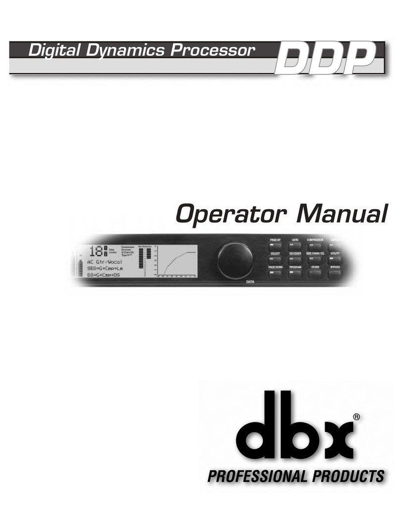
Harman dbx DDP User manual

Harman

Harman dbx DDP User manual

Harman AMX SVSI N2135A User manual

Harman

Harman AMX SVSI N2135A User manual

Harman AMX NMX-ENC-N2612S-C User manual

Harman

Harman AMX NMX-ENC-N2612S-C User manual

Harman AMX NMX-ENC-N2312 User manual

Harman

Harman AMX NMX-ENC-N2312 User manual

Harman AMX N1122A Series User manual

Harman

Harman AMX N1122A Series User manual

Harman AMX NMX-ENC-N2151 User manual

Harman

Harman AMX NMX-ENC-N2151 User manual

Harman AMX N2300 SERIES User manual

Harman

Harman AMX N2300 SERIES User manual

Harman AMX N Series User manual

Harman

Harman AMX N Series User manual

Harman AMX NMX-DEC-N2622S User manual

Harman

Harman AMX NMX-DEC-N2622S User manual

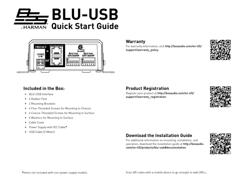
Harman BSS BLU-USB User manual

Harman

Harman BSS BLU-USB User manual

Harman AMX N2400 Series User manual

Harman

Harman AMX N2400 Series User manual

Harman AMX NMX-ENC-N2412A User manual

Harman

Harman AMX NMX-ENC-N2412A User manual

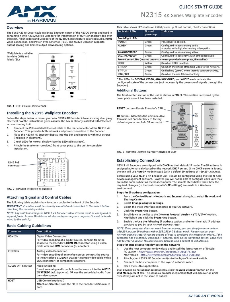
Harman AMX N2315 User manual

Harman

Harman AMX N2315 User manual

Harman AMX NMX-ENC-N2612S User manual

Harman

Harman AMX NMX-ENC-N2612S User manual

Harman AMX N3000 Series User manual

Harman

Harman AMX N3000 Series User manual

Harman AMX NMX-DEC-N2625-WP User manual

Harman

Harman AMX NMX-DEC-N2625-WP User manual

Harman AMX N2424A Series User manual

Harman

Harman AMX N2424A Series User manual

Popular Media Converter manuals by other brands

Baumer Hubner EtherNet/IP HMG10 operating manual

Baumer

Baumer Hubner EtherNet/IP HMG10 operating manual

Siko WH58M User information

Siko

Siko WH58M User information

DVDO DVDO-VGAHDMI-1 user manual

DVDO

DVDO DVDO-VGAHDMI-1 user manual

M-system JAPD instruction manual

M-system

M-system JAPD instruction manual

Renishaw HS20 installation guide

Renishaw

Renishaw HS20 installation guide

Transition Networks CGFEB10xx-12x user guide

Transition Networks

Transition Networks CGFEB10xx-12x user guide

Generac Power Systems S2502 installation manual

Generac Power Systems

Generac Power Systems S2502 installation manual

Matrox Maevex 6152 user guide

Matrox

Matrox Maevex 6152 user guide

Ferport SA04PLUS Instructions for use and installation

Ferport

Ferport SA04PLUS Instructions for use and installation

Tactical technologies TPC-48 installation manual

Tactical technologies

Tactical technologies TPC-48 installation manual

Dolby Laboratories DP591 quick start guide

Dolby Laboratories

Dolby Laboratories DP591 quick start guide

ASEA AC125V-3 Operation manual

ASEA

ASEA AC125V-3 Operation manual

Astone HDCN0007M1 user manual

Astone

Astone HDCN0007M1 user manual

ZIMO MX10 manual

ZIMO

ZIMO MX10 manual

Lika Posicontrol IF55 LIN CB Series Mounting instructions

Lika

Lika Posicontrol IF55 LIN CB Series Mounting instructions

RGBlink MSP 210V quick start

RGBlink

RGBlink MSP 210V quick start

Wavtech link2 owner's manual

Wavtech

Wavtech link2 owner's manual

CYP QU-DV12DL Operation manual

CYP

CYP QU-DV12DL Operation manual

manuals.online logo
manuals.online logoBrands
  • About & Mission
  • Contact us
  • Privacy Policy
  • Terms and Conditions

Copyright 2025 Manuals.Online. All Rights Reserved.