DAN DRYER 288 User manual

2 MB
USER MANUAL
STAINLESS DESIGN TURBO HAND DRYER
Model: 288 / 249

2 3
Dimensions
Unit of measurement: mm
TECHNICAL SPECIFICATIONS
DESCRIPTION DATA
Operating voltage 110V-120V, 50/60Hz, 1.3-1.6kW
220V-240V, 50/60Hz, 1.3-1.6kW
Air temperature 55°C ~ ambient temperature 20°C
Air speed 75-100 m/s (adjustable)
Motor type 350-700W (adjustable)
Motor thermal protection Auto resetting, thermostat turns off at:
120V at 135°C
240V at 95°C
Heating element 350-700W (adjustable)
Heating element protection Auto resetting, thermostat turns circuit off at: 85°C,
thermal fuse turns off at 142°C
Drying time ≤ 10 seconds
Stand-by power 0.3-0.4W
Sensor type Infra red
Sensor range 100-230 mm adjustable. Standard 170 mm± 20 mm
Protection timer 60 seconds auto shut off
IP Class IP21
Insulation class Class 1
Net weight 5.7 kg
Gross weight 6.5 kg
PRODUCT TYPE / MODEL
288 / 249 Stainless steel, TURBO Design hand dryer, 230V/110V
IMPORTANT!
This product falls within the scope of the WEEE directive
on recycling and recovery of waste electrical and electronic
equipment.
• This product should not be disposed of with general household waste.
• This product must be reused if possible.
• Contact your local authority for further details.
• This product may also be returned to the manufacturer/retailer for proper treatment,
recovery, and recycling
Dimensions and technical specications 3
General safety information 4
Circuit diagram 4
Installation 5
Product application 6
Recommended installation height 6
Cleaning and maintenance 6
Adjustment of air speed output and temperature 7
Adjustment of sensor range 7
Troubleshooting and corrective actions 8
Symptoms and corrective actions: New hand dryer 8
Symptoms and corrective actions: Used hand dryer 8
Parts list 9
TABLE OF CONTENTS DIMENSIONS AND TECHNICAL SPECIFICATIONS
200 198
420

L
N
4 5
CONNECTION:
A.
Connect Live wire (red or brown) to the terminal
block marked ”L”
B.
Connect Neutral wire (blue) to the terminal block
marked ”N”
C.
Connect Ground wire (green and yellow) to terminal
block marked ” ”
WARNING
• All units must be equipped with a 3-wire service. Connect the ground wire according to the
instructions.
• This product must be installed only by qualied persons. Use 2.0 mm2 (AWG) NO.14 wiring.
• Turn off the power to the unit before servicing or cleaning. All wires must be disconnected.
• Incorrect installation, defect power cords, or failure to properly ground unit could result in
electrical shock or life-threatening injuries
NOTE
We do not recommend to install this product less than 300 mm above washbasin, tabletop or
other surface. This product is suitable for indoor use only.
Type Y connection: If the power supply cord is damaged, it must be replaced immediately.
Only qualied persons shall be permitted to replace the cord to avoid a hazard. Disconnect the
electricity supply cord according to instructions.
This product is not intended for use by persons (inclusive children) with reduced physical,
sensory or mental capabilities, or lack of experience and knowledge, unless they are
supervised or have been given instruction concerning use of the product by a person
responsible for their safety.
Children should be supervised to ensure this product is used correctly.
GENERAL SAFETY INFORMATION INSTALLATION
CIRCUIT DIAGRAM
• Make sure the main breaker is turned off. Installation must be carried out by
a qualied person in accordance with standards applicable in the country where the
equipment is to be installed.
• Place template against the wall at desired height (see mounting height
recommendations).
!
NOTE
Colours of live and neutral wires depend on the
supply voltage.
5. Connect supply wires to terminal block:
1. Dismount the casing by removing the 2
securing screws.
3. Attach the base plate of the hand
dryer to the wall with the screws
supplied with the unit
4. Insert the power cord through the inlet hole.
Fasten with the retaining clip
2. Place the template
on the wall
at the desired location
(see recommended
installation height).
Drill (4) holes as
indicated.

6 7
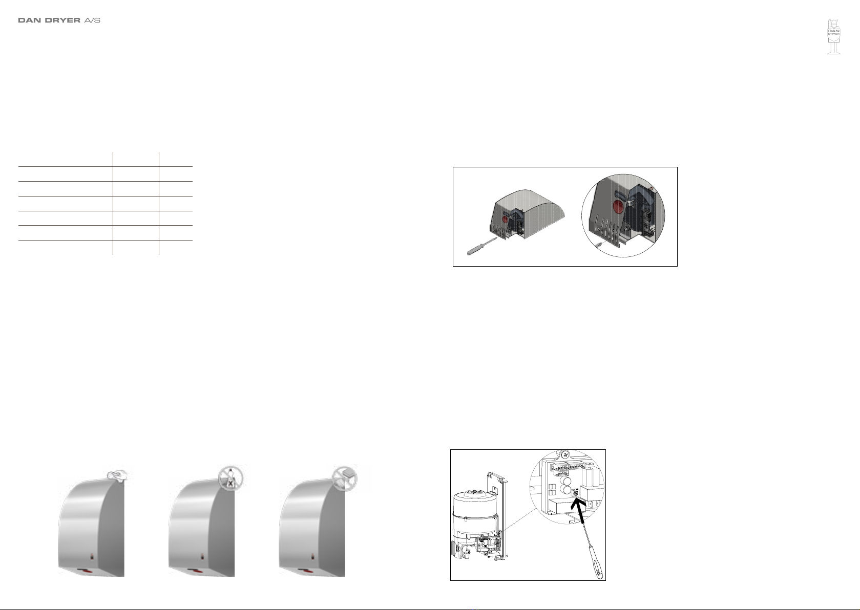
ADJUSTMENT OF AIR SPEED AND TEMPERATURE
• Insert Philips screwdriver or flat notch through the hole at the bottom of the cover and
place the screw head on the potentiometer screw (see drawing below)
• Adjust air speed and temperature on the VR potentiometer:
Clockwise to increase air speed and temperature (+)
Counterclockwise to decease air speed and temperature (-)
• Be careful not to overturn the adjustment screw
ADJUSTMENT OF SENSOR RANGE
The sensor range is adjsutable between 100 mm and 230 mm. Standard range 170 mm
± 20 mm.
• Switch off power and dismount the cover by loosening (2) screws at the bottom
• Use a small Philips screwdriver or similar to adjust the sensor on the VR screw:
Clockwise to increase sensor activation range (+)
Counterclockwise to decrease sensor activation range (-)
• The sensor activation range should be adjusted to its environments, e.g. light and
distance to the bottom of the sink
• Be careful not to overturn the sensivity adjustment
RECOMMENDED INSTALLATION HEIGHT
From bottom edge of hand dryer above nished floor.
Men 1270 mm (50”)
Women 1194 mm (47”)
Children 4-7 years 889 mm (35”)
Children 8-10 years 991 mm (39”)
Children 11-13 years 1092 mm (43”)
Children 14-16 years 1194 mm (47”)
Wheelchair users 1016 mm (40”)
PRODUCT APPLICATION
• Shake excess water from hands
• Place hands under the dryer to turn it on
• Rub hands lightly and rapidly
• Stops automatically after hands are removed.
CLEANING AND MAINTENANCE
Routine cleaning and maintenance is recommended every 12 months.
• Cut the power
• Unscrew (2) bottom security screws
• Remove the cover
• Clean the cabinet inside and remove dust/dirt. You can use compressed air
• Check carbon brushes in the motor. If carbon brushes are worn (≤ 10 mm graphite
remaining), they must be replaced
• Clean sensor lense on both sides
• Do not rinse with running water
• Use a damp cloth and mild cleaning solution. Never use cleaning detergents with an
abrasive effect
• Replace cabinet front and tighten screws. Be careful not to overtighten screws

Kabinet
Nylon-b¯sning til hul til kabelindgang
TrÊkaflastningsb¯jle
KlemmerÊkke
Jordskrue
St¯ddÊmper
BlÊserhus, top
Gummipakning til blÊserhus (stor)
Motor, 700 W
Gummipakning til blÊserhus (lille)
Varmelegeme, 900 W
UdblÊsningsstuds
Beslag til sensor
Sensor
OphÊng til blÊserhus
Bagplade
Potentiometer
Beslag til potentiometer
Timer
BlÊserhus, bund
Kabinetskrue (2 stk.)
Unbrakon¯gle til kabinetskruer
12
13
14
15
16
17
18
19
20
21
22
RESERVEDELE, TURBO DESIGN
8 9
No. Description
1 Housing
2 Nylon bushing for cable inlet hole
3 Cable clamp
4 Terminal block
5 Earthing screw
6 Shock absorber
7 Blower housing - upper part
8 Rubber gasket for blower housing
(large)
9 Motor, 700W
10 Rubber gasket for blower housing
(small)
11 Heating element, 900W
12 Outlet branch
TROUBLESHOOTING AND CORRECTIVE ACTIONS PARTS LIST
SYMPTOM CORRECTIVE ACTION: NEW HAND DRYER
The dryer does not run • Check power supply to the product and ensure the
connections at the terminal block are made properly.
The dryer cycles by itself and
runs constantly • Make sure nothing is obstructing the IR-sensor activa-
tion area.
• If problem persists, check the recommended installa-
tion height.
The dryer is very loud and
does not run for a complete
cycle
• Ensure power supply is correct
• If the timer is damaged, replace both timer and sensor
Hand dryer runs randomly
and stops before the cycle is
nished
• Check timer and sensor. Replace if required.
The hand dryer runs, but the
airspeed is low • Ensure the voltage is correct.
• Check setting of potentiomenter for air speed adjust-
ment (see page 7).
SYMPTOM CORRECTIVE ACTION: USED HAND DRYER
Hand dryer does not start • Check power supply to the product and ensure the
connections at the terminal block are made properly.
IR-sensor only detects motion
when hands are placed really
close to the hand dryer
• Make sure nothing is obstructing the IR-sensor.
• Clean sensor. If the problem persists, disconnect the-
power and remove the cabinet, taking suitable precau-
tion to avoid schock hazard.
• Carefully adjust sensor range (see paragraph on this
subject).
• If the problem persists, replace sensor and timer.
The dryer gets hot, but there is
no air stream • Disconnect the power. Remove the cover and disas-
semble the blower/fan unit.
The dryer blows only cold air
during a full cycle • Disconnect the power.
• Remove the cover and disassemble the blower/fan
unit.
• Check the heating element thermostate for open
circuit.
• Check the heating element for defects. Replace defect
heating element.
Hand dryer does not run
smoothly • Check carbon brushes. Replace if they are worn or
damaged. If no faults are detected, replace motor.
No. Description
13 Gasket for sensor
14 Sensor
15 Bracket for blower housing
16 Backplate
17 Potentiometer
18 Bracket for potentiometer
19 Timer
20 Blower housing – lower part
21 Housing screws (2 pcs.)
22 Allen key for housing screws

DAN DRYER A/S
Alsikevej 8
DK - 8920 Randers NV
T: +45 8641 5711
E: info@dandryer.com
W: dandryer.com
This manual suits for next models
2
Table of contents
Other DAN DRYER Dryer manuals
Popular Dryer manuals by other brands

Maytag Commercial
Maytag Commercial MEDP575GW installation instructions

Whirlpool
Whirlpool AWG 367 Instructions for use

Zanussi
Zanussi TCE 7276 W Instruction booklet

Electrolux Professional
Electrolux Professional Compass Pro TD6-17S installation manual

Dimplex
Dimplex AirDryer DAD25 owner's manual

Asko
Asko TD75.13 Series Instructions for use