DAN DRYER 346-347-348 User manual

USER MANUAL
TURBO LOW NOISE HAND DRYER
Model: 346-347-348 / 250-251-254

2
IMPORTANT!
This product falls within the scope of the WEEE directive
on recycling and recovery of waste electrical and electronic
equipment.
Dimensions and technical specications 3
General safety information 4
Circuit diagram 4
Installation 5
User guide 6
Recommended installation height 6
Cleaning and maintenance 6
Adjustment of warm air speed output 7
Heating element switch 7
Adjustment of sensor range 7
Troubleshooting and corrective actions 8
Symptoms and corrective actions of rst-time installed hand dryers 8
Symptoms and corrective actions of used hand dryers 8
Parts list 9
TABLE OF CONTENTS
• This product should not be disposed of with general household waste.
• This product must be reused if possible.
• Contact your local authority for further details.
• This product may also be returned to the manufacturer/retailer for proper treatment,
recovery, and recycling.

3
Dimensions
Unit of measurement: mm
TECNICAL SPECIFICATIONS
DESCRIPTION DATA
Operating voltage 110V-120V, 50/60Hz, 10.8-11.7A, 1.19-1.4kW
220V-240V, 50/60Hz, 5.4-5.8A, 1.19-1.4kW
Air temperature 55°C ~ ambient temperature 25°C
Air speed 65-95 m/s (adjustable)
Motor type 350-700W (adjustable) carbon brush with double ball bearings,
12000-18000 rpm. Lifespan of carbon brushes: Approx. 580K
activations
Motor thermal protection Auto resetting, thermostat turns off at 135°C
Heating element 350 - 700W (adjustable)
Heating element protection Auto resetting, thermostat turns circuit off at: 85°C,
thermal fuse turns off at 142°C
Drying time ≤ 15 seconds
Stand-by power 0.3-0.4W
Sensor type Infrared, self adjusting
Sensor range 100-230 mm adjustable. Standard 170mm± 20mm
Protection timer 60 seconds auto shut off
IP Class IP31 or IP33 (option)
Insulation class Class 1
Net weight 5.5 kg
Gross weight 6.1 kg
PRODUCT TYPE / MODEL
346 / 250 White enamel coated steel, Turbo Low Noise hand dryer, 230V/110V
347 / 251 Stainless steel, brushed, Turbo Low Noise hand dryer, 230V/110V
348 / 254 Black powder coated stainless steel, Turbo Low Noise hand dryer, 230V/110V
DIMENSIONS AND TECHNICAL SPECIFICATIONS

4
WARNING
• All units must be equipped with a 3-wire service. Connect the ground wire according
to the instructions.
• This product must be installed only by qualied persons. Use 2.0mm2(AWG) NO.14 wiring.
• Turn off the power to the unit before servicing or cleaning. All wires must be disconnected.
• Incorrect installation, defect power cords, or failure to properly ground unit could result in
electrical shock or life-threatening injuries.
NOTE
We do not recommend to install this product above a washbasin. Installation above reflective
surfaces will cause the hand dryer to start on its own. This product is suitable for indoor use
only.
Type Y connection: If the power supply cord is damaged, it must be replaced immediately.
Only qualied persons shall be permitted to replace the cord to avoid a hazard. Disconnect
the electricity supply cord according to instructions.
This product is not intended for use by persons (inclusive children) with reduced physical,
sensory or mental capabilities, or lack of experience and knowledge, unless they are
supervised or have been given instruction concerning use of the product by a person
responsible for their safety.
Children should be supervised to ensure this product is used correctly.
GENERAL SAFETY INFORMATION
CIRCUIT DIAGRAM
!
Circuit Board Module
L
N
G/Y
Brown
Blue
Black
Black
Only 110/120V
Motor With Thermal Switch 2A
Red
Heater with Thermo-fuse
White
VR FOR SPEED
VR FOR SENSOR
Sensor module
Transistor
Power Switch
Thermostat
NMO2HE2 MO1 HE1L

5
INSTALLATION
1: Remove the two screws in the lower
area of the unit and remove the casing
from its base.
5: Replace the casing and fasten with two
screws in the lower area
3: Connect supply wires to terminal block
4: Attach mounting plate
securely with four screws
2: Insert the power cord through the inlet
hole.
Connections:
A. Connect LIVE to terminal “L”
B. Connect NEUTRAL to terminal “N”
C. Connect GROUND to terminal “ “
Make sure the main breaker is turned off. Installation must be carried out by a
qualied person in accordance with standards applicable in the country where
the equipment is to be installed.
Place template against the wall at desired height (see mounting height recommendations)
and mark location of (4) mounting holes and the wire service entry.
Note: If several products are installed in close proximity to each other, the minimum
distance between the products should be 610 mm from the centerline of each product.

6
RECOMMENDED INSTALLATION HEIGHT
From bottom edge of hand dryer above nished floor.
CLEANING AND MAINTENANCE
Routine cleaning and maintenance is recommended every 12 months to ensure your hand
dryer is running at optimal performance.
• Disconnect the electrical supply.
• Remove the two cover-mounting screws.
• Remove the casing.
• Clean the interior of the dryer and remove any dust.
• Check carbon brushes. If carbon brushes are worn, they must be replaced.
The estimated lifespan for carbon brushes is 580K activations.
• Do not soak.
• Use a damp cloth and mild cleaning solution. Never use cleaning
detergents with an abrasive effect.
• Replace the cover. Do not overtighten the screws.
USER GUIDE
• No-touch operation.
• Shake excess water from hands.
• Place hands under the outlet to start operation.
• Rub hands lightly and rapidly.
• Stops automatically after hands are removed.
Men 1270 mm (50”)
Women 1194 mm (47”)
Children, 4-7 years 889 mm (35”)
Children, 8-10 years 991 mm (39”)
Children, 11-13 years 1092 mm (43”)
Children, 14-16 years 1194 mm (47”)
Wheelchair users 1016 mm (40”)

7
WARM AIR SPEED ADJUSTMENT
• Switch off the power and remove the cover.
• Use Phillips screwdriver or flat notch.
The air speed is adjusted on the VR potentiometer.
Clockwise to increase air speed(+).
Counterclockwise to decrease air speed(-).
SENSOR RANGE ADJUSTMENT
• The sensor range adjustable between 100mm and 230mm.
Standard range: 170mm ± 20mm
• Clockwise: To increase sensor activation range (+)
• Counterclockwise: To decrease sensor activation range (-)
• The sensor activation range should be adjusted to its environments,
e.g. light and distance to the bottom of the sink.
Note: Do not overturn the sensivity adjustment.

8
TROUBLESHOOTING AND CORRECTIVE ACTIONS
SYMPTOM CORRECTIVE ACTION: FIRST-TIME INSTALLED HAND
DRYERS
The dryer does not run First ensure that the breaker supplying the dryer is opera-
tional. If it is, disconnect the power and remove the cover.
Taking suitable precaution to avoid shock hazard, recon-
nect the power and check for voltage on the terminal block.
Verify that connections are made correctly.
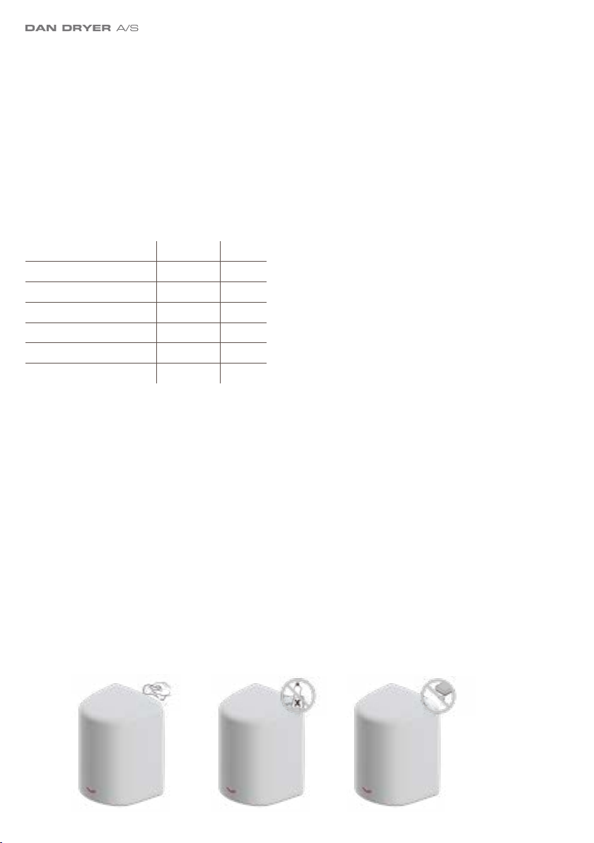
The dryer cycles by itself and
runs constantly Ensure that there is no obstruction on or in front of the IR
sensor. Clean any dirt off the sensor lens. If problem per-
sists, replace the sensor.
The dryer is very loud and
does not run for a complete
cycle
Ensure that the supply voltage is correct. The dryer will
make a loud humming noise if the input voltage is too high.
Verify voltage requirement on the unit rating label and
correct accordingly. If PCB is damaged, replace unit as well
as IR sensor.
The dryer runs, but the
airspeed is low Ensure that the supply voltage is correct. The dryer will run
slowly if the input voltage is too low.
SYMPTOM CORRECTIVE ACTION: USED HAND DRYERS
The dryer does not run First ensure that the breaker supplying the dryer is opera-
tional. If it is, disconnect the power and remove the cover.
Replace PCB and IR sensor. Taking suitable precaution to
avoid shock hazard, reconnect the power and check for vol-
tage on the terminal block.
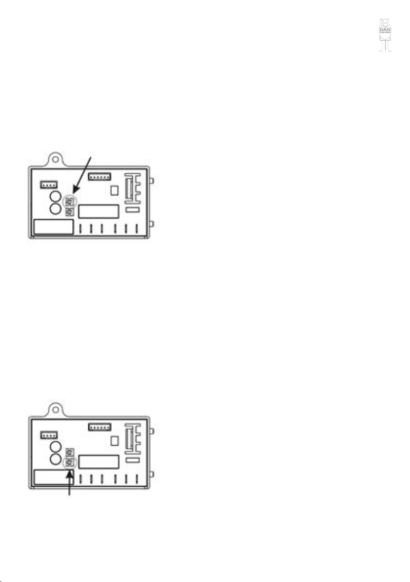
The IR-sensor detects only
close range objects Ensure that there is no obstruction on or in front of the IR
sensor. Clean any dirt off the sensor lens. If problem per-
sists, disconnect the power and remove the cover. Taking
suitable precaution to avoid shock hazard, reconnect the
power and try carefully adjusting the sensitivity range (yel-
low slot in blue component on PCB). If problem persists,
replace IR sensor.
The dryer gets hot, but there is
no air stream Disconnect the power. Remove the cover and disassemble
the blower/fan unit. Replace motor.
The dryer blows only cold air
during a full cycle Disconnect the power. Remove the cover and disassemble
the blower/fan unit. Test the thermostate for open circuit.
Check the heating element for defects. Replace defect
heating element.
The air pressure is low Check the output nozzle for obstructions. If none, discon-
nect the power and remove the cover. Remove any dirt from
the inlet. Disassemble the blower/fan unit, check if motor
brushes are worn (≤ 10 mm graphite remains) and replace
them, if necessary.

9
PARTS LIST
No. Description
1 Casing, black, white, or brushed steel
2 Security hex screw, (2 reqd.)
3 Security hex wrench
4 Blower housing, upper
5 Motor rubber, large
6 Motor
7 Motor rubber, small
8 Blower housing, lower
9 Heating element
10 Air outlet
11 LED panel
12 Air outlet bracket
13 Timer, with IR sensor
14 Sensor bracket
15 Rubber bushing (4 reqd.)
16 Base plate
17 Grounding screw
18 Filter kit (option)
19 HEPA lter kit (option)
20 P-clips
21 Insulation mylar
22 Terminal block
23 Sensor module

10
DAN DRYER A/S
Alsikevej 8
DK - 8920 Randers NV
T: +45 8641 5711
E: info@dandryer.dk
W: dandryer.com
This manual suits for next models
1
Table of contents
Other DAN DRYER Dryer manuals