DAN DRYER 244 Turbo Manual

Reference Version Document Lang. Page
244-ENG 09-01-2018 244 DAN DRYER Turbo (with nozzle)
Maintenance and service manual ENG 1 of 12
DAN DRYER A/S • Tåsingevej 2 • DK-8940 Randers SV • Tel: +45 86 41 57 11 • Email: info@dandryer.dk
Version Description of changes Page(s)
Version history
244 DAN DRYER Turbo (with nozzle)
Maintenance and service manual

Reference Version Document Lang. Page
244-ENG 09-01-2018 244 DAN DRYER Turbo (with nozzle)
Maintenance and service manual ENG 2 of 12
DAN DRYER A/S • Tåsingevej 2 • DK-8940 Randers SV • Tel: +45 86 41 57 11 • Email: [email protected]
Table of Contents:
Preface 2
General 2
Intended product use 2
The supplier's product liability 2
Safety and warnings 2
Installation and connection 3
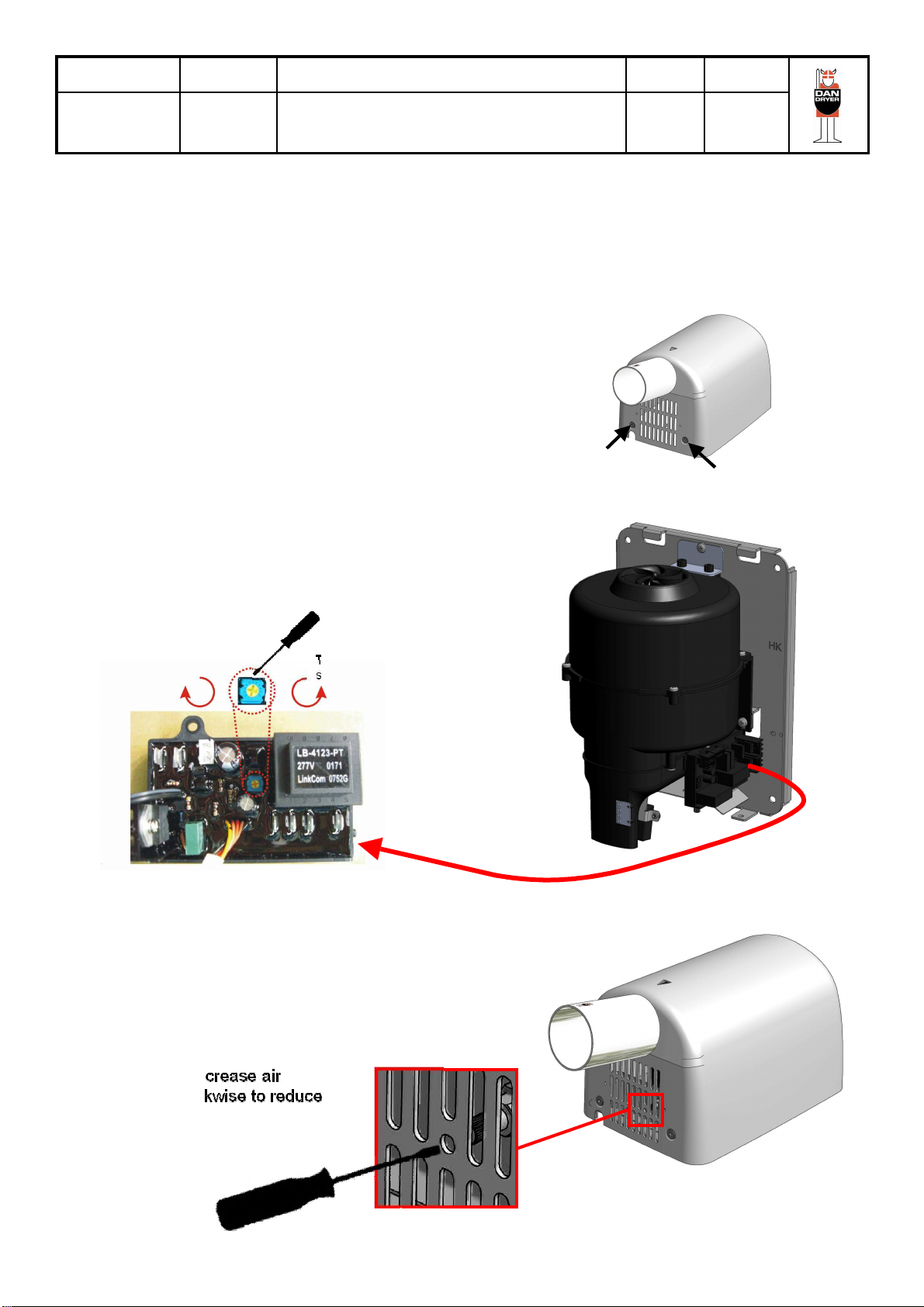
Adjustment of the machine 4
Regular maintenance 5
Fault finding and solutions 5
Cleaning the inside of the machine 6
Spare parts 9
Carbon brush replacement 10
Heating element replacement 11
Technical specifications 12
Wiring chart 12
General
The hand dryer must only be installed and
used in accordance with these instructions and
safety precautions. All service staff who work
with installation, servicing and repair of the
machine must have read and understood this
manual. If you have questions concerning the
use or maintenance of your machine, you are
welcome to contact us.
Intended product use
The hand dryer is designed for installation in
indoor public or private restrooms and may
only be used for hand drying.
The supplier's product liability:
DAN DRYER A/S accepts no responsibility if
the machine is installed, used, modified or
composed otherwise than specified in this
manual.
Note !!!
The machine is designed for indoor use only.
Preface
Thank you for purchasing your equipment from
DAN DRYER A/S and congratulations on your
new hand dryer. If you use and maintain your
hand dryer according to our manual, it will work
to your satisfaction for many years. Safety Precautions:
Check before use that:
the hand dryer is securely attached to
the wall.
the hand dryer is properly cleaned.
the hand dryer is not damaged or
otherwise in disorder.
Warning !!!
During cleaning, inspection, service etc.
the hand dryer must always be
disconnected from the power supply.
Warning !!!
If the hand dryer is not installed and
connected properly it can be dangerous to
use due to the risk of electric shock.
Always follow the installation instructions
in this manual.
All service staff who work with servicing
and repairing of the machine must have
read and understood this manual.
Safety Precautions:
Maintenance work requiring dismantling of
the machine must only be carried out by
staff with proper training so the work can
be carried out in a secure manner.

Reference Version Document Lang. Page
244-ENG 09-01-2018 244 DAN DRYER Turbo (with nozzle)
Maintenance and service manual ENG 3 of 12
DAN DRYER A/S • Tåsingevej 2 • DK-8940 Randers SV • Tel: +45 86 41 57 11 • Email: [email protected]
Installation and connection:
To protect the user against electric shock, it is important that the hand dryer is connected to the earth wire.
For fixed installation, connect via circuit breaker.
Remove the
cover screws Remove the
cover screws
Transport
protection block
Cut-out for
wiring through
the bottom
Hole for wall
mounting
screw
Hole for
hidden wiring
Hole for wall
mounting
screw
Hole for wall
mounting
screw
Hole for wall
mounting
screw
1. Remove transport protection block prior to
installation.
2. Remove the two cover screws at the bottom of
the cover using the supplied special Allen key.
Carefully remove the housing from the base
plate.
3. Attach the base plate to the wall using
appropriate screws in the four mounting
holes. Wiring can be hidden behind the
machine or may alternatively be fed through
the bottom of the cover.
4. Connect wires as follows:
A. Connect the live wire (red or brown) to the
terminal block marked ”L”.
B. Connect the neutral wire (blue or black) to
the terminal block marked ”N”.
C. Connect the green and yellow earth wire to
the screw marked ” ”.
5. Remount the cover using the two cover
screws at the bottom of the cover and
test run the hand dryer.
If the machine is mounted in an enclosed
cabinet, it is important to be aware of the
following requirements:
If the hand dryer is installed in an enclosed cabinet
it is important that there is enough space to
remove the hand dryer's cover so the machine is
easily accessible for cleaning or servicing.
Total area of ventilation
holes must be at least
35 cm2per hand dryer.
If the cabinet has a fixed
front plate, there must
be at least 200 mm
space to dismantle and
remove the hand dryer's
cover.
Do not lift the
hand dryer by
the electrical
parts during
installation.
The turbo hand dryer sucks a large amount of air
during operation. It is therefore important that the
cabinet/housing has ventilation holes of at least
35 cm2 for each hand dryer.

Reference Version Document Lang. Page
244-ENG 09-01-2018 244 DAN DRYER Turbo (with nozzle)
Maintenance and service manual ENG 4 of 12
Remove the
cover screws Remove the
cover screws
The sensing range of the hand dryer is pre-set by the manufacturer.
We recommend that the sensing range is NOT adjusted by the user.
If you wish to modify the sensing range anyway, please proceed according to the following instructions:
Sensing range adjustment:
1. Cut off the power supply to the hand dryer
2. Remove the cover by loosening the Allen screws at the
bottom of the housing. This can be done with the special
Allen key originally supplied with your hand dryer.
3. The sensing range adjusting screw is located as shown
in Fig. 1.
Use a tiny screwdriver to carefully turn the adjusting screw.
a. Turn clockwise to lengthen the sensing range.
b. Turn counter-clockwise to shorten the sensing range.
4. Remount housing and test run the hand dryer.
Turn counter-clockwise to
shorten the sensing range.
Turn clockwise to lengthen
the sensing range.
Air speed adjustment:
Turn clockwise to increase air
speed and anti-clockwise to reduce
air speed.
Fig. 1
If a lower noise level is desired, air speed may be
adjusted by turning the adjusting screw located inside
and at the bottom of the hand dryer cover.
DAN DRYER A/S • Tåsingevej 2 • DK-8940 Randers SV • Tel: +45 86 41 57 11 • Email: [email protected]

Reference Version Document Lang. Page
244-ENG 09-01-2018 244 DAN DRYER Turbo (with nozzle)
Maintenance and service manual ENG 5 of 12
DAN DRYER A/S • Tåsingevej 2 • DK-8940 Randers SV • Tel: +45 86 41 57 11 • Email: [email protected]
Regular maintenance:
To ensure a continued satisfactory function of the hand
dryer it is recommended regularly to remove dust etc. from
the machine.
The frequency of cleaning depends on the environment in
which the hand dryer is installed and how often it is used.
If the machine is used often cleaning is recommended at
least once a month.
Exhaust pipe and sensor must be cleaned with a damp
brush (available from DAN DRYER)
Cleaning / vacuuming of the air intake holes in the hand
dryer's cover and any air intake holes in the cabinet /
furniture.
If the machine is rarely used, we recommend cleaning
once every 6 months.
Exhaust pipe and sensor must be cleaned with a damp
brush (available from DAN DRYER)
Cleaning / vacuuming of the air intake holes in the hand
dryer's cover and any air intake holes in the cabinet /
furniture.
In the event that the machine is used extensively and the
environment is very dusty, it may be necessary to clean
the inside of the machine regularly. See more in the
section "Cleaning the inside of the machine"
Cleaning / vacuuming
of the air intake holes
Important: To ensure correct
function the IR sensor must
always be completely clean.
Problem: Solution:
Hand dryer does not start:
Check the 230V power supply.
Check IR sensor for dirt or damages.
Check that all electrical connections, wires etc. are intact.
If none of the above actions corrects the problem, it is either the IR sensor, the
coal brushes or the timer that causes the problem and must be replaced.
Blows cold air only: Heating element unit has been overheated and must be replaced.
Timer is defective and must be replaced.
Poor air flow: Dirt and dust in inlet and outlet impair the air flow. Clean the machine and
cabinet in accordance with the section "Regular maintenance"
Other problems not covered by this guide: If the problem is not resolved by the above actions the entire hand dryer unit
must be sent for repair to DAN DRYER or replaced with a new one.
Trouble shooting:
IMPORTANT:
If the unit is returned to DAN DRYER it must be accompanied by a detailed description of
the problem.

Reference Version Document Lang. Page
244-ENG 09-01-2018 244 DAN DRYER Turbo (with nozzle)
Maintenance and service manual ENG 6 of 12
DAN DRYER A/S • Tåsingevej 2 • DK-8940 Randers SV • Tel: +45 86 41 57 11 • Email: [email protected]
Cleaning the inside of the machine
1.Disassemble cover by removing the two cover
screws at the bottom of the housing. Use the
special Allen key which was originally supplied
with the hand dryer.
Warning !!!
During cleaning and service the hand dryer must always be disconnected from the power supply.
Remove the
cover screws Remove the
cover screws
3.Remove the four screws (B). Disassemble the
top half of the motor housing
(B)
(B)
(B)
(B)
4.Carefully lift up the motor whilst taking note
how the motor was positioned inside the
housing and how the motor wires are placed in
the protective grooves (C)
6.Check whether carbon brushes are worn down
and need to be replaced. If so, disassemble by
removing the screws and by disconnecting
wires from carbon brush terminals.
2.Disassemble angle bracket by removing the
screw (A)
(A)
5.Disconnect motor wires from the timer unit
(appearance depends on the timer type).
Place the motor on a table upside-down.

Reference Version Document Lang. Page
244-ENG 09-01-2018 244 DAN DRYER Turbo (with nozzle)
Maintenance and service manual ENG 7 of 12
DAN DRYER A/S • Tåsingevej 2 • DK-8940 Randers SV • Tel: +45 86 41 57 11 • Email: [email protected]
Cleaning the inside of the machine
7.Use compressed air (max. 8 bar) to remove dirt
and carbon dust from the motor and motor
housing. If compressed air is not available,
parts may be cleaned with a soft brush or
gently with a vacuum cleaner.
9.The heating element is placed at the bottom of
the motor housing. Clean it using compressed air
(max. 8 bar). Blow from both sides, and be
careful not to damage the heating element.
10. Put the small rubber gasket back in place at
the bottom of the fan housing. Be careful
not to turn it upside down, cf. photo ref. 11.
12.Reconnect motor wires to the timer unit
(appearance depends on the timer type).
Please be careful not to damage wires.
8.Lift the large rubber gasket out of the top of the
motor housing. Clean it and degrease with alcohol.
Clean the small rubber gasket placed at the bottom
of the motor housing in the same manner.
11. Put the motor back in the bottom part of
the fan housing. Make sure that the motor
rests properly between the two ”forks”
and on the small rubber gasket.

Reference Version Document Lang. Page
244-ENG 09-01-2018 244 DAN DRYER Turbo (with nozzle)
Maintenance and service manual ENG 8 of 12
DAN DRYER A/S • Tåsingevej 2 • DK-8940 Randers SV • Tel: +45 86 41 57 11 • Email: [email protected]
Cleaning the inside of the machine
13. Put the large rubber gasket back on top of the
motor.
15. Assemble the top of the fan housing onto the
bottom part by tightening the four screws. Be
careful not to overtighten. Fix angle bracket to
base plate of the motor
16. Reassemble hand dryer cover.
14. Reassemble the top half of the motor housing.
Make certain that motor wires are safely placed
in the protective groove.
Refit the cover
screws
17. Reconnect power supply and test run dryer.
Refit the cover
screws

Reference Version Document Lang. Page
244-ENG 09-01-2018 244 DAN DRYER Turbo (with nozzle)
Maintenance and service manual ENG 9 of 12
DAN DRYER A/S • Tåsingevej 2 • DK-8940 Randers SV • Tel: +45 86 41 57 11 • Email: [email protected]
Spare parts
1. Housing
2. Bushing for hole for cable entry
3. Tensile relief clamp
4. Terminal block
5. Earth screw
6. Shock absorber
7. Fan housing, top
8. Rubber gasket for fan housing (large)
9. Motor, 700 W
10. Rubber gasket for fan housing (small)
11. Heating element, 900 W
12. LED unit
13. Air outlet
14. Mounting bracket for sensor
15. Sensor
16. Mounting bracket for fan housing
17. Base plate
18. Potentiometer
19. Mounting bracket for potentiometer
20. Timer
21. Fan housing, bottom part
22. Housing screw (2 pcs.)
23. Allen key for housing screws

Reference Version Document Lang. Page
244-ENG 09-01-2018 244 DAN DRYER Turbo (with nozzle)
Maintenance and service manual ENG 10 of 12
DAN DRYER A/S • Tåsingevej 2 • DK-8940 Randers SV • Tel: +45 86 41 57 11 • Email: [email protected]
Carbon brush replacement
3.Disassemble angle bracket.
1.Disconnect power supply.
2.Disassemble cover by removing the two
cover screws at the bottom of the housing.
Use the special Allen key which was
originally supplied with the hand dryer.
4.Loosen the 4 screws
on the fan housing and
disassemble fan
housing lid.
5.Gently lift up the motor.
Be careful not to damage
motor wiring.
6.Loosen carbon brush wiring.
7.Loosen the 2 x 2 screws,
allowing for the worn
brushes to be disassembled
from the motor.
8.Assemble new carbon
brushes and reassemble
screws and wires.
9.Reassemble all components
and test run hand dryer.
Warning !!!
During cleaning and service the hand dryer
must always be disconnected from the
power supply.

Reference Version Document Lang. Page
244-ENG 09-01-2018 244 DAN DRYER Turbo (with nozzle)
Maintenance and service manual ENG 11 of 12
DAN DRYER A/S • Tåsingevej 2 • DK-8940 Randers SV • Tel: +45 86 41 57 11 • Email: [email protected]
Heating element replacement
3.Disconnect wires from timer unit.
4.Disassemble sensor bracket and
timer unit from fan housing.
1.Disconnect power supply.
2.Disassemble cover by removing the two
cover screws at the bottom of the housing.
Use the special Allen key which was
originally supplied with the hand dryer.
5.Loosen the two screws and dismount fan
housing from base plate.
6.Loosen the screws and disassemble air outlet
from fan housing.
7.Disassemble heating element from air outlet.
8.Assemble new heating element and
reassemble all other components.
9.Reassemble all components and test
run hand dryer.
Warning !!!
During cleaning and service the hand dryer
must always be disconnected from the
power supply.

Reference Version Document Lang. Page
244-ENG 09-01-2018 244 DAN DRYER Turbo (with nozzle)
Maintenance and service manual ENG 12 of 12
DAN DRYER A/S • Tåsingevej 2 • DK-8940 Randers SV • Tel: +45 86 41 57 11 • Email: [email protected]
Technical specifications
Power supply: 220 - 240 V 50-60Hz
Power consumption: 1600 W
Thermal cut-out: 142 C
IP rating: IPX1
CE labeled according to relevant EN standards in the directives 2004/108 / EC (EMC)
and 2006/95 / EC (Low Voltage).
Expected lifetime of hand dryer (before replacing the brushes): 216.000 hand dryings
Expected lifetime of hand dryer (after replacing the brushes): 108.000 hand dryings.
Expected total lifetime of hand dryer before disposal: 324.000 hand dryings.
Expected total lifetime
Dimensions:
Wiring chart:
Table of contents
Other DAN DRYER Dryer manuals
Popular Dryer manuals by other brands

Dexter Laundry
Dexter Laundry DDAD30HC-59 Series Dryers Operator's manual

AEG
AEG LAVATHERM 8DBG842 user manual

Parker Zander
Parker Zander KE-MT Series operating manual

Bosch
Bosch WTG84260ES Installation and operating instructions

Siemens
Siemens WT47W540BY Installation and operating instructions

Beko
Beko B3T4911DW user manual