DANA Spicer Drive Axles User manual

Service Manual
AXSM0029
September 2007
Spicer®Drive Axles

General Information
General Information
The description, testing procedures, and specifications contained in this service publication were current at the time of printing.
Dana reserves the right to discontinue or modify its models and/or procedures and to change specifications at any time without
notice and without incurring obligation.
The recommendations of the vehicle manufacturer should be considered as the primary source of service information regarding
this Spicer product. This manual is intended to be used as a supplement to such information.
Any reference to brand names in this publication is made simply as an example of the types of tools and materials recommended
for use and, as such, should not be considered as an endorsement. Equivalents, if available, may be used.
This symbol is used throughout this
publication to call your attention to areas
in which carelessness or failure tofollow
specific procedures may result in
personal injury and/or component
malfunction or damage.
Anyone departing from the
instructions contained in this
publication through procedures
used or choice of tools, materials
and parts may jeopardize his personal
safety and/or the safety of the vehicle user.
WARNINGS: Used in areas
where failure to follow listed
procedures creates a high
probability of personal injury
to the servicing technician.
CAUTIONS: Used in areas
where failure to follow listed
procedures may cause personal
injury due to component
damage or subsequent malfunction.
IMPORTANT NOTICE
Always use genuine Spicer replacement parts.

i
Table of Contents
Electric Shift System
Introduction
Electric Shift System . . . . . . . . . . . . . . . . . . . . . . . . . 1
Mechanical Operation . . . . . . . . . . . . . . . . . . . . . . . . 2
Troubleshooting . . . . . . . . . . . . . . . . . . . . . . . . . . . . 5
Shift Unit Removal/Disassembly
Remove Shift Unit . . . . . . . . . . . . . . . . . . . . . . . . . . . 8
Remove Slider Block . . . . . . . . . . . . . . . . . . . . . . . . . 8
Remove Circuit Board and Motor . . . . . . . . . . . . . . . 9
Remove Gear and Cam Pins . . . . . . . . . . . . . . . . . . 10
Cleaning. . . . . . . . . . . . . . . . . . . . . . . . . . . . . . . . . . 10
Lubrication . . . . . . . . . . . . . . . . . . . . . . . . . . . . . . . 10
Sealing. . . . . . . . . . . . . . . . . . . . . . . . . . . . . . . . . . . 10
Shift Unit Assembly/Installation
Install Cam Pins and Gear . . . . . . . . . . . . . . . . . . . . 11
Install Slider Block. . . . . . . . . . . . . . . . . . . . . . . . . . 12
Install Motor . . . . . . . . . . . . . . . . . . . . . . . . . . . . . . 13
Install Circuit Board . . . . . . . . . . . . . . . . . . . . . . . . . 14
Install Shift Unit. . . . . . . . . . . . . . . . . . . . . . . . . . . . 15
Shift Unit Retrofit Kits
Retrofitting Instructions. . . . . . . . . . . . . . . . . . . . . . 16
Servicing Other Electric System Components
Installation of Improved Motor Housing Cover
(Production units effective December 1989) . . . . . . 17
Speedometer Adapter . . . . . . . . . . . . . . . . . . . . . . . 18
Control Switch . . . . . . . . . . . . . . . . . . . . . . . . . . . . . 18
Air Shift System
Air Shift System
Description . . . . . . . . . . . . . . . . . . . . . . . . . . . . . . . 19
Operation . . . . . . . . . . . . . . . . . . . . . . . . . . . . . . . . 19
Air Shift Unit . . . . . . . . . . . . . . . . . . . . . . . . . . . . . . 20
Description and Operation (Shift Unit) . . . . . . . . . . 20
Troubleshooting . . . . . . . . . . . . . . . . . . . . . . . . . . . 21
Shift Unit Removal/Disassembly
Remove Shift Unit . . . . . . . . . . . . . . . . . . . . . . . . . . 22
Disassemble Shift Unit . . . . . . . . . . . . . . . . . . . . . . 22
Lubrication . . . . . . . . . . . . . . . . . . . . . . . . . . . . . . . 23
Parts Inspection . . . . . . . . . . . . . . . . . . . . . . . . . . . 23
Shift Unit Assembly/Installation
Assemble Shift Unit. . . . . . . . . . . . . . . . . . . . . . . . . 24
Install Shift Unit . . . . . . . . . . . . . . . . . . . . . . . . . . . 25
Air Shifter Valve Removal/Disassembly
Remove/Disassemble Air Shifter Valve . . . . . . . . . . 26
Inspection/Lubrication . . . . . . . . . . . . . . . . . . . . . . 26
Air Shifter Valve Assembly/Installation
Assemble/Install Air Shifter Valve . . . . . . . . . . . . . . 27
Servicing Other Air System Components
Quick Release Valve . . . . . . . . . . . . . . . . . . . . . . . . 28
Pressure Switch . . . . . . . . . . . . . . . . . . . . . . . . . . . 28
Servicing Other Air System Components
Additional Service Information . . . . . . . . . . . . . . . . 29
Parts Information . . . . . . . . . . . . . . . . . . . . . . . . . . 29

1
Electric Shift System
Introduction
The service procedures and specifications in this publication
cover the current Spicer 2-Speed Axle Shift Systems.
Maintenance and overhaul instructions for the Spicer 2-Speed
Axle carriers are covered in the publications listed on the back
cover.
This manual includes information on two types of Shift Sys-
tems currently in use for Spicer 2-Speed Axles; Electric and
Air.
Spicer 2-Speed Axles are driver-controlled by means of a shift
unit operated from the vehicle cab. These shift units are acti-
vated by air or electric power depending on the convenient
source in the chassis.
Because of this variation, this publication is divided into two
major segments: Electric Shift System for hydraulic-brake
chassis and Air Shift System for air-brake chassis.
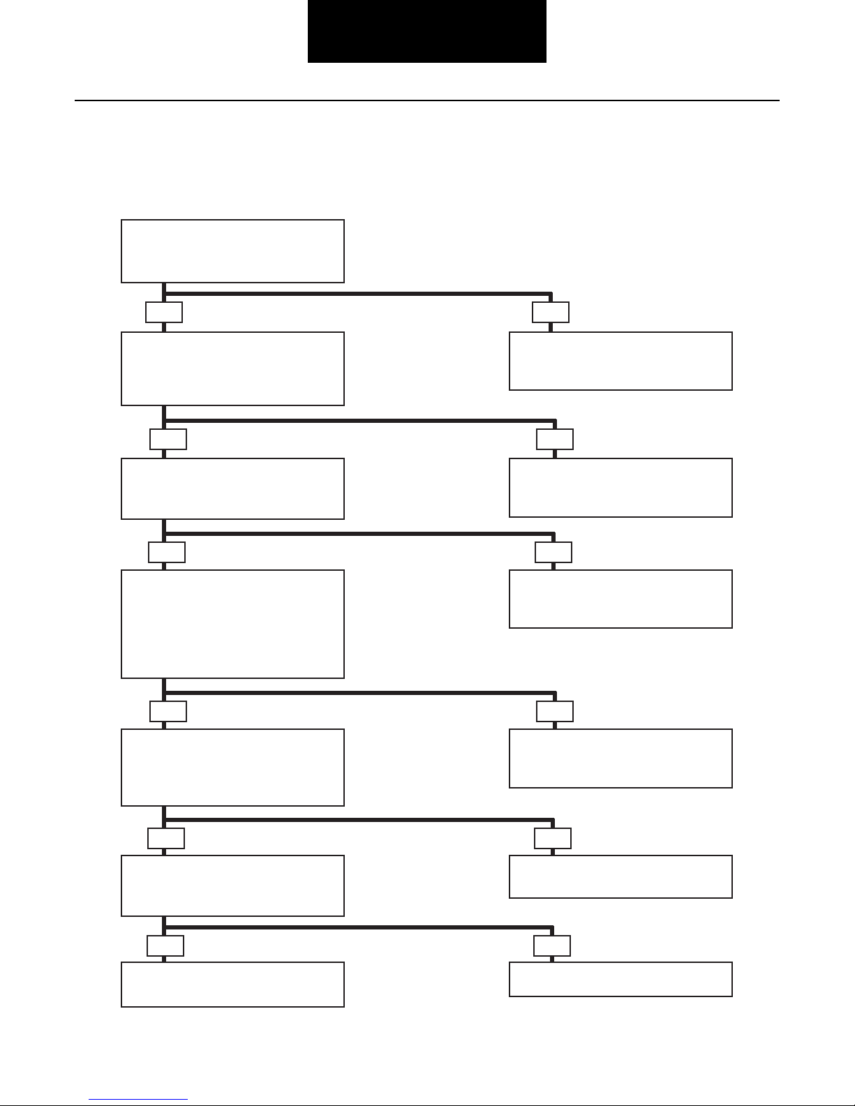
Electrical Operation
Note: For component identification and wiring schematic,
refer to illustrations on pages 1, 2, 3, and 4.
Unit in Low Range Shifting to High Range
Current flows through upper contact of control switch, closed
contacts of high-range switch, and motor to ground which
starts the motor rotating. Current also continues from com-
mon motor terminal through low-range switch and to ground
through the resistor.
When motor starts, rotation of the gear allows cam ramp to
apply pressure on low-range cam pin, which allows low range
switch to open. The path to ground (through resistor) is open
and the diode prevents speedometer adapter solenoid from
being energized.
Motor rotation continues to shift axle to high range. As shift is
completed, cam ramp of gear releases high-speed cam pin to
open high-range switch and creates an open circuit to turn off
power to motor. Motor rotation is stopped quickly by means
of dynamic braking through resistor.
If, during rotation, driver decides to switch back to low range,
motor continues to turn.
Opening of high-range switch has no effect since motor is
now being powered by the circuit from control switch,
through diode and low-range switch to ground at motor. In
this instance, motor continues to turn until cam pin opens
low-range switch to turn off power to motor.
Unit in High Range Shifting to Low Range
Current flows through control switch lower contact to ener-
gize speedometer adapter solenoid and through the diode and
low-range switch to common motor terminal and ground at
motor. Motor starts rotating. Current also flows through
closed contact of high-range switch and to ground through
resistor. Once gear rotates enough to apply cam pin pressure
on the high switch, circuit to ground through resistor is open.
As motor rotation continues to shift axle to low range, gear
rotates and releases cam pin on low-range switch to open
switch and open motor circuit. Motor poweris turned off.
Once again, the resistor portion of the circuit provides braking
to stop motor quickly.
If, during motor rotation, driver decides to shift back to high
range, the motor continues to turn. Opening of low-range
switch has no effect since motor is now being powered
through control switch. In this instance, motor continues to
turn until gear rotation opens high-range switch to open
motor circuit.
The shift unit always remains synchronized with position of
driver's control switch.
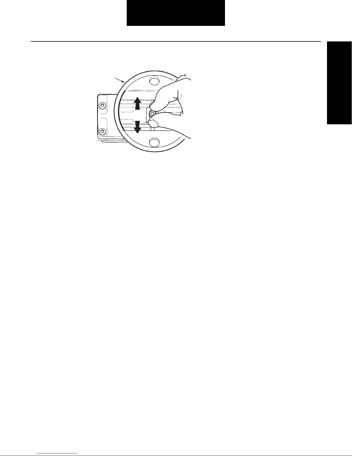
ELECTRIC SHIFT UNIT CUTAWAY
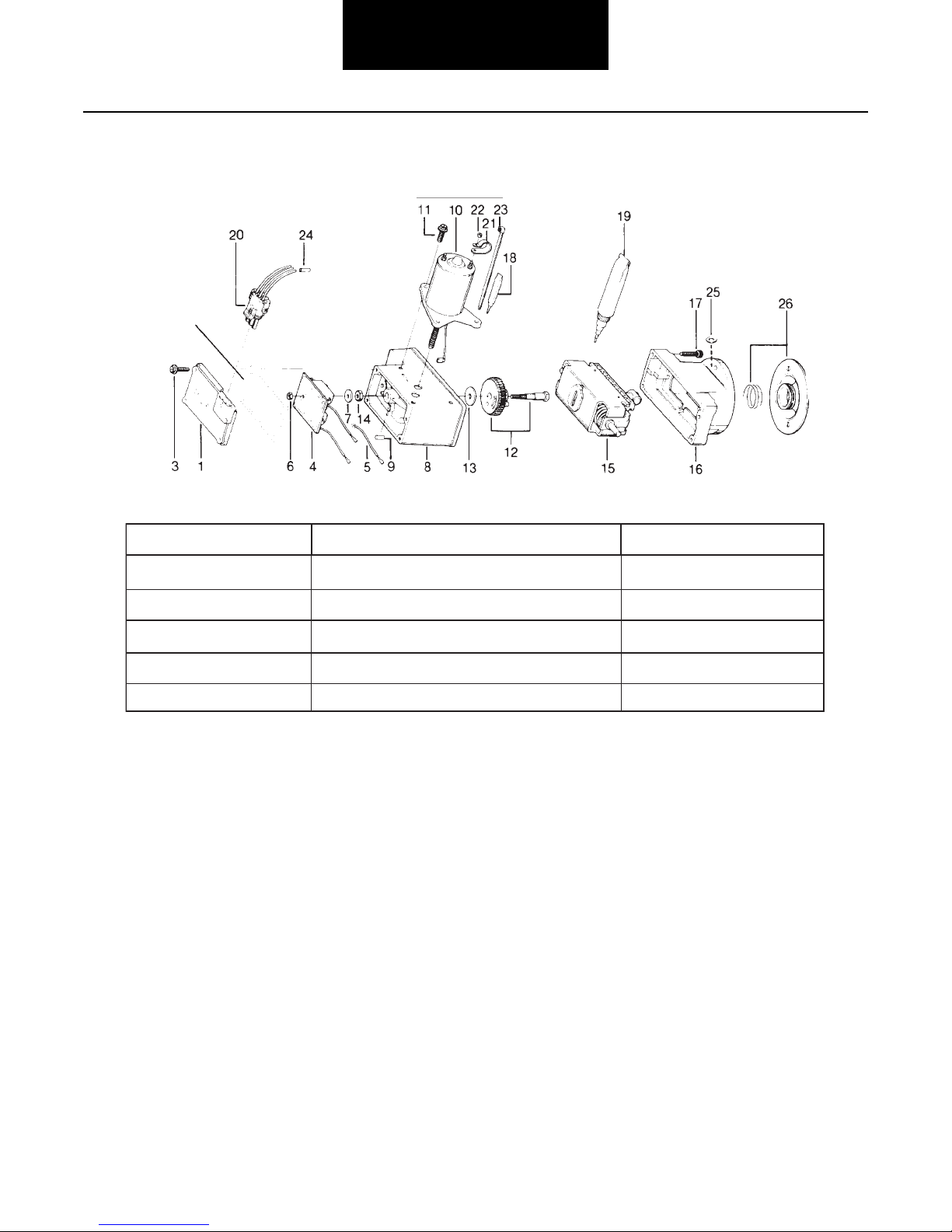
Wiring Harness
and Connector
Black Wire
Green Wire
Red Wire
Worm Gear
Cam Pin
(High Range)
Slider
Block
Flat Washer
(0.100",
2.54 mm
thick)
Gear Pin
(Eccentric)
Gear
Switch
Spring
Cam Pin
(Low Range)
Circuit Board
Assembly
Motor

2
Electric Shift System
General Information
Mechanical Operation
Low to High Range or High to Low Range
When shifting axle range either up or down, motor starts and
turns worm gear shaft. The gear assembly (which is meshed
with worm gear) turns and moves eccentric pin in slot area of
slider block.
Since driving torque holds shift fork and swivel block of the
slider block assembly in place, linear motion of slider block is
translated into compression of the internal spring.
As motor shuts off at 180º of gear rotation, a break in torque
by driver allows spring force (stored in the slider block
assembly) to move the swivel pin and shift fork in appropriate
direction for axle range change.
When opposite axle range is selected by driver, the process is
repeated by motor turning another 180º in same direction. In
this case though, eccentric pin movement creates block
spring compression in the opposite direction.
Note: The new improved housing cover does not require a
gasket (see page 17).
ELECTRIC SHIFT UNIT
Housing Cover
CoverGasket
Nut (Circuit Board)
Circuit Board Assembly
Red Wire
Black Wire
GreenWire
Cam Pin
MotorHousing
CoverScrew
CoverGasket
(See Note below)
Wiring Harness
and Connector
Board Flat Washer
Nut (GearShaft)
Worm Gear
MotorScrew
MotorAssembly
Nut
Cable Clip
MotorLead Wire
Electric Shift Unit Assembly
Housing Screw
Nut
Flat Washer(0.100", 2.54 mm thick)
Stud
Seal & Spring
Dowel Pin
Base Housing
SliderBlock &
Shaft Assembly
GearWasher
Gear
GearPin
GearShaft

3
Electric Shift System
Shift System Electrical Wiring Schematic
Electrical Shift System Major Components
PowerSource
(Ignitionor
Accessory Switch)
Up-High
Range
Down-Low
Range Switch Knob
Motor
Circuit
Breaker
Speedometer
Adapter
Wiring
Harness
Control Switch
Ground
Housing
Cover
Wiring
Harness
Connector
Black
Green
Red
Ground
Circuit Board
Resistor
Ground
Black Switches
Low
Range
NO NC
Diode
High
Range
NC NO
Shift Unit Switch
Plug and Cable
Assembly
Speedometer
Adapter
Circuit Breaker
orFuse
Front Wiring
Harness
RearWiring
Harness
Electric
Shift Unit

4
Electric Shift System
General Information
Slider Block Inspection Procedure
Bottom of
Base Housing
• Remove shift unit from axle.
• Move sliderblock from side to side.
Make sure sliderblock movesfreely
inhousing.

5
Electric Shift System
Troubleshooting
Troubleshooting Guide
This chart begins with an improperly operating shift unit. Use with illustrations on pages 3, 4 and 6 to help isolate the problem.
Follow the possible solutions as an aid to system repair.
• Replace worn components.
• Repeat troubleshooting procedure.
Axle doesn’tshiftranges.
• Check the circuit breaker.
• Isthe circuit breakerclosed?
NoYes
Check forpoweratthe shiftunit
connector.
• Isthere a voltage reading of 9V
ormore?
• Reset circuit breakeror
replace fuse.
• Repeat troubleshooting procedure.
NoYes
Remove shiftunitfrom axle and
apply voltage.
• Doesunit shift properly?
• Check the battery, cab switch,
wire harness, and connectors.
• Repeat troubleshooting procedure.
NoYes
Inspectsliderblock from bottom
of shiftunit. See page 4
• Check to see if sliderblock isloose
ormissing.
• Issliderblock ingood operating
condition?
• Disassemble and service shift unit.
(See page 8)
• Repeat troubleshooting procedure.
NoYes
Inspectappearance of shiftfork
and check fitwith depth card.
• Doesthe fork match the depth
card output? (See page 6)
• Replace sliderblock assembly
(See page 8)
• Repeat troubleshooting procedure.
NoYes
Remove and inspectaxle shiftparts.
• Are engagement surfacesseverely
worn, chipped orbroken?
• Rework orreplace shift fork.
• Repeat troubleshooting procedure.
No
Yes
End of diagnostics

6
Electric Shift System
General Information
Checking Shift Fork Position and Alignment
Electric shift unit failure or shifting problems may be caused
by the shift fork binding on the slider block. Check the shift
fork position and alignment with the Shift Fork Fit-Up card.
Refer to the instructions on the card and the illustration below
to check the shift fork.
If interference at points Aand Bexists, carefully grind shift
fork until it matches the fit-up card.
Shift Fork Fit-up Card Shift Fork
Range Position
Hi
Lo
FORWARD-REAR AXLE
Figure 1
Lo
Hi
Shift Fork
Range Position
REAR-REAR AND SINGLE AXLES
Shift Fork
Fit-up Card
Shift Fork Fit-up Card
(Part No. 128039)
•Fit-up Card must set flush
on mounting surface of axle
• Shift fork must NOT touch
Fit-up Card at points Aand B
Procedure:
1. Shift axle to high range so fork is
square to axle face.
2. Remove shift unit and rubber boot.
3. Drop card over shift unit as shown
in (fig. 1) until card touches carrier
surface or interferes with fork.
4. If no interference, fork is OK.
Go to step #6.
5. If card interferes at A or B, care-
fully grind fork to fit template.
6. Replace boot and reassemble unit.
Dana service keeps
you on the road.
For technical assistance call
1-877-777-5360
anywhere in North America
Part no. 128039
10M/1290/MP
Copyright Dana 1991
All right reserved
2-Speed Shift Fork Fit-Up Card
Printed in U.S.A.

7
Electric Shift System
Parts Service Kits
Expanded Service Kits
Note: The new
and improved
housing cover
doesNOT
require a
gasket
(see page 17).
211319
113745
113746
113759
113753
Circuit Board and Cover Kit
Motor and Lube Kit
Drive Gear and Cam Pin Kit
Slider Block and Lube Kit
Connector and Harness Kit
1-7, 18-19
10, 18-19
5, 9, 12-14, 18
15, 18
20-26
SERVICE KIT NO. DESCRIPTION ITEMS INCLUDED

8
Electric Shift System
Removal / Disassembly
Shift Unit Removal/Disassembly
Remove Shift Unit
1. Shift axle to low range and park vehicle.
2. Disconnect wiring harness at shift unit.
3. Remove nuts, flat washers and shift unit from car-
rier.
Note: When shift unit is removed, provide container to catch
oil that escapes from carrier.
4. Remove shift unit seal and spring assembly.
Remove Slider Block
Note: To remove slider block, it is necessary to separate base
housing from motor housing. Gasket compound may
cause these housings to stick together. Use the motor
as a handle to assist in separating the housings. If nec-
essary, carefully pry housings apart using a thin-blade-
screwdriver.
1. Remove cap screws fastening base housing to
motor housing.
2. Lift motor housing off base housing.
3. Lift out slider block and shaft assembly.
Base
Housing
MotorHousing
SliderBlock
and
Shaft Assembly

9
Electric Shift System
Remove Circuit Board and Motor
1. Remove cap screws fastening cover to motor hous-
ing.
Note: Gasket compound may cause cover to stick to housing.
If necessary, carefully pry it loose, using a thin-blade
screwdriver.
2. Disconnect lead wires at cover terminals. Remove
cover and gasket. Remove circuit board locknut.
3. Lift circuit board out to gain access to motor lead
wire (black). Disconnect this wire then remove cir-
cuit board.
4. Remove circuit board mounting washer.
5. Remove cap screws fastening motor.
6. Lift motor to separate it from the housing.
Note: Gasket compound may cause motor to stick to housing.
If necessary, separate motor from housing by carefully
prying, using a thin-blade screwdriver.
7. Remove motor, carefully guiding the motor wire and
terminal through the housing hole.
HOUSING COVER REMOVAL
Circuit Board
LocknutLead Wires
CoverTerminals
Disconnect Motor
Lead Wire
Remove
Circuit Board
Washer
MOTOR REMOVAL
Pry motorloose
with screwdriver

10
Electric Shift System
Removal / Disassembly
Remove Gear and Cam Pins
1. Remove gear locknut. Use deep-well socket while
holding shaft end with locking pliers.
2. Remove ground lead wire.
3. Lift shaft and gear assembly out of housing.
Note: The cam pins are removed from the gear side of hous-
ing. Do not disturb the switch spring.
4. Remove cam pins from housing.
Cleaning
After shift unit disassembly, clean all parts (with exception of
the motor and circuit board), in a suitable commercial solvent.
Dry with clean, lint-free cloth or compressed air before lubri-
cating or reassembly.
Make sure all residual gasket compound is removed from
mating surfaces.
WARNING: Gasoline is not an acceptable solvent because
of its extreme combustibility. It is unsafe in the workshop
environment.
Lubrication
Lubrication of the shift unit is not required except when unit
has been disassembled. Instructions are contained in the shift
unit assembly procedures in this manual.
Note: Use only “Rheolube 362” for shift lubrication. Use of
other lube types may cause shift unit operational prob-
lems under certain low temperature conditions. A tube
of this lubricant is included in Spicer Shift Unit Service
Kits. It can also be purchased separately under Part
No. 113741.
Sealing
CAUTION: Use approved gasket compound (Part No.
113771) to seal shift unit cover and other components.
Standard RTV sealant may cause corrosion of electrical
components.
Proper sealing of the shift unit mating surfaces is essential for
long life and trouble-free operation. For effective sealing, use
approved gasket compound. During reassembly, make sure
the mating surfacesare clean and that the compound pattern
is not disturbed. Also, the gasket compound will set in 20
minutes. Assemble components before compound sets or
reapply.
Use locking pliers
and deep-well socket
to loosen nut
GEAR SHAFT LOCKNUT REMOVAL
Remove cam pins
from housing
WARNING
CAUTION

11
Electric Shift System
Shift Unit Assembly/Installation
Install Cam Pins and Gear
Note: Use “Rheolube 362” lubricant during following reas-
sembly procedures. Use of other lube types may cause
operational problems under certain low temperature
conditions.
1. Lubricate pins. Install pins in motor housing.
2. Lubricate both sides of gear washer and gear face
that contacts gear washer.
3. Liberally apply lubricant on gear teeth. Completely fill
cavities between teeth.
4. Lubricate the shoulder part of the gear shaft. Assem-
ble shaft, gear and washer, then place this assembly
in motor housing.
Lubricate and install
cam pins
Lubricate
gearface
Lubricate
gearteeth

12
Electric Shift System
Assembly / Installation
5. Connect ground lead wire. Install gear locknut. While
holding shaft end with locking pliers, torque locknut.
6. After installation, rotate gear in a COUNTERCLOCK-
WISE direction to make sure binding is not present.
Clockwise rotation is prevented by shift unit design.
Install Slider Block
Use “Rheolube 362” lubricant during following reassembly
procedures. Use of other lube types may cause operational
problems under certain low temperature conditions.
1. Apply a light film of lubricant to the full length of the
slider block shaft. Fill entire slot area of slider block
with lubricant (the area which engages gear pin).
Also fill the cavity next to the gear with lubricant
(cavity adjacent to motor shaft hole).
2. Rotate gear to position the gear pin at 90 degrees
from the slider block shaft centerline (see illustration
below). Install slider block by nesting the block shaft
in the recessed pockets in base housing.
Note: It may be necessary to move the slider block in one
direction or the other to engage the gear pin.
Install gear
locknut
Connect ground
lead wire
Rotate gearto
check forbinding
Lubricate
SLIDER BLOCK LUBRICATION
Gearpin
SLIDER BLOCK INSTALLATION

13
Electric Shift System
3. With housing mating surfaces clean, apply a contin-
uous bead of approved gasket compound around the
outer edge of the base housing. Align the dowel pin
with hole in motor housing and assemble the two
housings.
4. Install housing cap screws loosely. Make sure that
housings are mating properly by wiggling the slider
block from side to side.
5. Torque housing cap screws.
Note: There should be some slider block free play. If block is
rigid, loosen cap screws, reposition block and tighten
cap screws finger-tight. Recheck slider block free play.
Install Motor
1. Apply a continuous bead of approved gasket com-
pound on motor base around motor shaft and lead
wire.
2. Place motor on housing, guiding the lead terminal
and wire through the proper opening and placing
shaft through motor housing hole.
3. Install cap screws and tighten to correct torque.
Apply gasket compound
Move sliderblock from side
to side to make sure housings
are properly mated
Apply gasket
compound

14
Electric Shift System
Assembly / Installation
Install Circuit Board
1. Install circuit board washer on gear shaft and on top
of gear locknut.
2. Connect motor lead wire to circuit board terminal.
3. Install circuit board on gear shaft and install locknut.
Torque locknut.
IMPORTANT: If a new housing cover is required, install the
improved cover (see page 17 for instructions). Original
cover is not available.
4. To continue assembly of the shift unit when reusing
the original cover, proceed as follows:
5. Apply RTV Electrical Grade Gasket Compound in
(PN 113771) cover gasket groove. Install gasket.
Apply gasket compound to gasket mating surface,
circling screw holes.
6. Connect circuit board lead wires to cover terminals
(see next illustration). Carefully push wires back in
housing.
Note: Exert care when repositioning lead wires to prevent
smearing or destroying gasket compound.
Install circuit
board washer
Connect
motor lead
IMPORTANT
Install circuit
board assembly
Install board locknut

15
Electric Shift System
7. Place cover in position on motor housing and install
cap screws. Torque cover cap screws.
Note: Cover includes terminal identification for lead wires:
B - Black, G - Green, R - Red inside and LO, GND and HI
outside.
Install Shift Unit
Note: Before installation, place shift unit in low range. This
can be accomplished by connecting chassis wiring har-
ness to shift unit cover and operating control switch (in
cab), or apply 12-volt power supply to low range and
ground terminals in shift unit cover (see wiring sche-
matic, page 3).
1. Lubricate shift fork in seal area. Install seal and
spring assembly on carrier.
2. Place shift unit on mounting studs, making certain
shift unit actuating swivel pin engages slot in shift
fork. Install flat washers (0.100", 2.54 mm thick) and
nuts.
3. Torque nuts. Connect wiring harness.
IMPORTANT: Before installing a rebuilt or replacement shift
unit, check fit of shift fork using a “fit-up” card (see
page 6).
Black
Wire
Red Wire
GreenWire
Connect lead wires
IMPORTANT

16
Electric Shift System
Retrofit Kits
Shift Unit Retrofit Kits
The new Spicer Electric Shift Unit is a completely new design
and shares no common parts with existing shift units. How-
ever, it is completely interchangeable as a unit for service
replacement. Retrofit Kits are available to convert to the new
shift unit.
Note: In some special situations, the new unit cannot be used.
Refer to appropriate Spicer Parts Books for detailed
application and part no. information.
The following instructions are a condensed version for retro-
fitting a new shift unit. Detailed instructions are contained in
the Retrofit Kit.
Retrofitting Instructions
*These parts are included in Retrofit Kit.
1. Remove existing shift unit.
2. Remove and discard seal and spring.
3. Cut existing wiring harness (approx. 6" - 8"). Identify
wires (Low Range, High Range and ground).
4. Connect new wiring harness to existing harness,
using connectors* furnished in kit.
5. Connect new wiring harness to new shift unit.*
Check shift unit operation before mounting on differ-
ential carrier. Operate driver control switch in low
and high range and observe new shift unit operation.
If shift unit does not operate, unplug new harness
connector and test for power and voltage continuity
at connector terminals.
If shift unit operates, install on carrier as follows:
6. Use new seal and spring assembly.* Mount seal on
carrier studs.
7. Install shift unit. Install flat washers and nuts.
Torque nuts.
Note: Make sure to use the mounting washers* (0.100",
2.54 mm thick) furnished with kit.
8. Attach cable clip* to harness near motor and fasten
to motor stud with nut*. Torque clip nut.
9. Secure harness to chassis with tie wraps.* Leave
adequate slack to allow for axle movement.
IMPORTANT: Shift Unit Replacement.
Before installing a rebuilt or new shift unit, check fit of shift
fork to slide block pivot using a “Fit-up” Card or Template
(PN 128039). These cards are furnished with new shift units
retrofit and slide block kits. Instructions are contained on
the card (see illustration) (also see page 6 instructions).
EXISTINGWIRING HARNESS NEW HARNESS*
Ground to Green Wire (Ground)
)woL(eriWkcalBotwoL
)hgiH(eriWdeRothgiH
Connectors (3)
Tie Wraps (2)
Shift
Unit
Assembly
Flat Washer (2)
(0.100", 2.54mm thick)
Cable
Clip
Clip
Nut
Wiring
Harness
Spring
Seal
COMPONENTS OF TYPICAL RETROFIT KIT
IMPORTANT
Procedure:
1. Shift axle to high range so fork is
square to axle face.
2. Remove shift unit and rubber boot.
3. Drop card over shift unit as shown
in (fig. 1) until card touches carrier
surface or interferes with fork.
4. If no interference, fork is OK.
Go to step #6.
5. If card interferes at A or B, care-
fully grind fork to fit template.
6. Replace boot and reassemble unit.
Dana service keeps
you on the road.
For technical assistance call
1-877-777-5360
anywhere in North America
Part no. 128039
10M/1290/MP
Copyright Dana 1991
All right reserved
2-Speed Shift Fork Fit-Up Card
Printed in U.S.A.

17
Electric Shift Sytem
Servicing Other Electric System Components
Installation of Improved Motor Housing
Cover (Production units effective Decem-
ber 1989)
The new cover (PN 113786) has a continuous sealing lip
around the outside edge which improves sealing against road
environment contamination. Previous cover is no longer avail-
able. Units currently in the field must be modified whenever a
new cover is installed.
Modification: Because the new cover encloses the entire rim
of the units cast nose piece, the base of the motor mounting
flange must be relieved slightly to prevent interference.
Note: This modification is only needed if a notch is NOT
present in the motor housing flange.
1. Remove four (4) cover screws. Retain 3 screws.
Note: The service kit includes a screw which is 1/4" longer
than the previous cover screws.
2. Place the new cover into position on the shift unit
housing and draw a reference line on the motor base
to show the width of the area to be modified.
3. Using a file or small die grinder, remove material
from the motor base (as shown in Fig. 1. The notch
should be at least 0.100" (2.5mm) deep and 0.150"
(3.8 mm) wide. Trial fit the cover during modifica-
tion.
CAUTION: When removing material, use care to avoid filing
into the threads of the motor mount fastener.
Fig. 1 - Electric Shift Unit Cover Fit Modifications
4. With the modification complete, install the new cover
as follows:
5. Using RTV gasket compound (supplied with the ser-
vice kit), apply a thin bead on top edge of motor
housing.
Note: The new cover does not require a gasket.
CAUTION: Always use RTV Electrical Grade Gasket Com-
pound (PN 113771). Standard forms of RTV generate
acetic acid which will damage shift unit components. Use
gasket compound sparingly. Excessive use of compound
could damage internal parts.
CAUTION
Cover
See Detail Below
Interference Area
Upper
Housing Motor
Upper
Housing
0.100"
2.5 mm
Motor
0.150"
4.0 mm
CAUTION
Table of contents
Other DANA Other manuals