Fostex XR-3 User manual

Owner’s
Manual
“
“
-
--
—
--
Model
XR-3
i
j
MULTITRACKER
j
Fostex
CAUTION
ms
RISK
OF
ELECTRIC
SHOCK
Wm
DO
NOT
OPEN
WB
CAUTION:
TO
REDUCE
THE
RISK
OF
ELECTRIC
SHOCK,
DO
NOT
REMOVE
COVER
(OR
BACK).
NO
USER-SERVICEABLE
PARTS
INSIDE.
REFER
SERVICING
TO
QUALIFIED
SERVICE
PERSONNEL.
CAUTION:
TO
PREVENT
ELECTRIC
SHOCK,
MATCH
WIDE
BLADE
OF
PLUG
TO
WIDE
SLOT,
FULLY
INSERT.
ATTENTION:
POUR
EVITER
LES
CHOCS
ELECTRIQUES,
INTRODUCE
LA
LAME
LA
PLUS
LARGE
DE
LA
FICHE
DANS
LA
BORNE
CORRE-SPONDANTE
DE
LA
PRISE
ET
POUSSER
JUSQ’
AU
FOND.
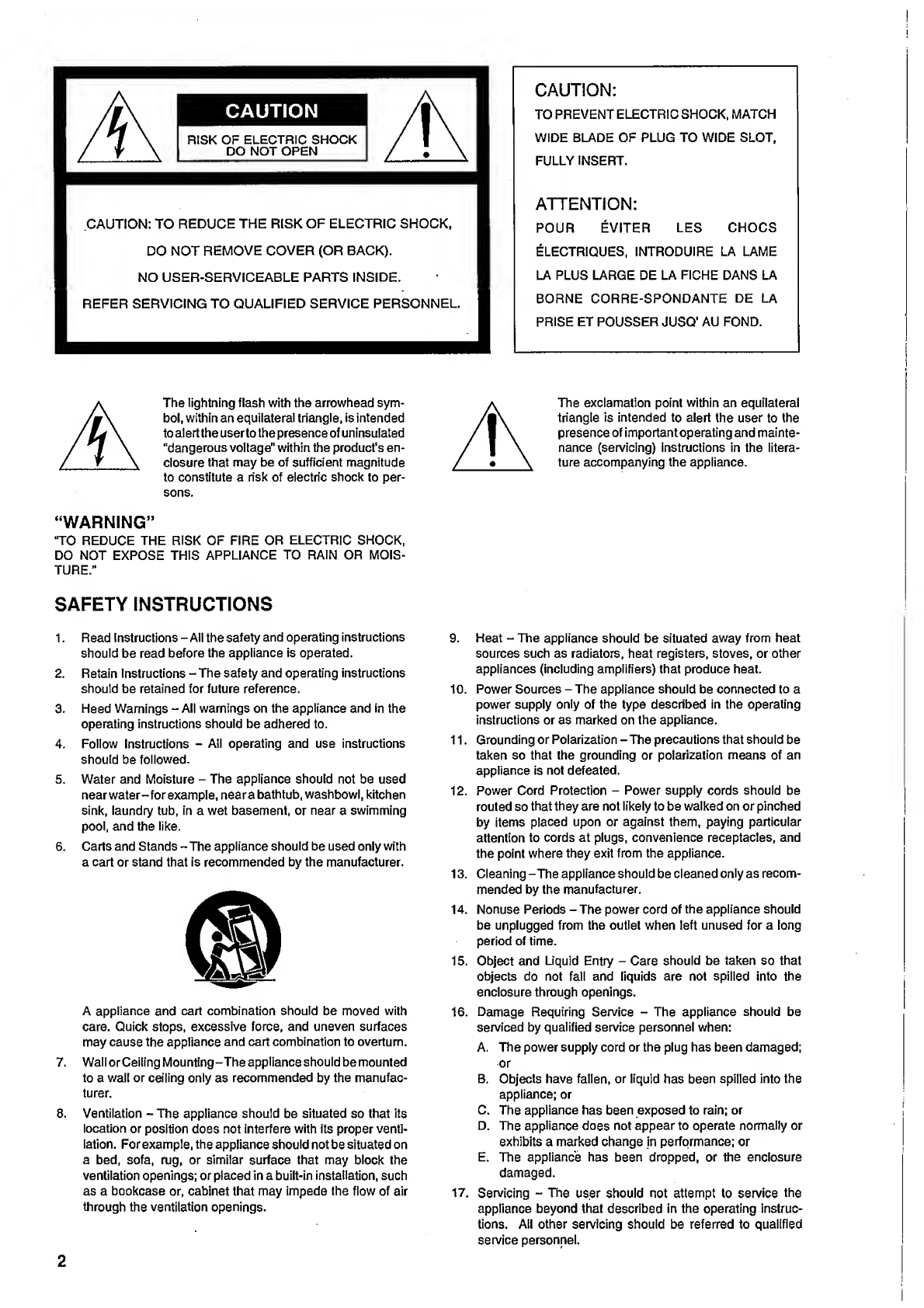
The
lightning
flash
with
the
arrowhead
sym¬
bol,
within
an
equilateral
triangle,
is
intended
to
alert
the
user
to
the
presence
of
uninsulated
“dangerous
voltage"
within
the
product's
en¬
closure
that
may
be
of
sufficient
magnitude
to
constitute
a
risk
of
electric
shock
to
per¬
sons.
“WARNING”
‘TO
REDUCE
THE
RISK
OF
FIRE
OR
ELECTRIC
SHOCK,
DO
NOT
EXPOSE
THIS
APPLIANCE
TO
RAIN
OR
MOIS¬
TURE.”
SAFETY
INSTRUCTIONS
1.
Read
Instructions
-
All
the
safety
and
operating
instructions
should
be
read
before
the
appliance
is
operated.
2.
Retain
Instructions
-
The
safety
and
operating
instructions
should
be
retained
for
future
reference.
3.
Heed
Warnings
-
All
warnings
on
the
appliance
and
in
the
operating
instructions
should
be
adhered
to.
4.
Follow
Instructions
-
All
operating
and
use
instructions
should
be
followed.
5.
Water
and
Moisture
-
The
appliance
should
not
be
used
nearwater-for
example,
neara
bathtub,
washbowl,
kitchen
sink,
laundry
tub,
in
a
wet
basement,
or
near
a
swimming
pool,
and
the
like.
6.
Carts
and
Stands
-
The
appliance
should
be
used
only
with
a
cart
or
stand
that
is
recommended
by
the
manufacturer.
A
appliance
and
cart
combination
should
be
moved
with
care.
Quick
stops,
excessive
force,
and
uneven
surfaces
may
cause
the
appliance
and
cart
combination
to
overturn.
7.
Wall
or
Ceiling
Mounting
-The
appliance
should
be
mounted
to
a
wall
or
ceiling
only
as
recommended
by
the
manufac¬
turer.
8.
Ventilation
-
The
appliance
should
be
situated
so
that
its
location
or
position
does
not
interfere
with
its
proper
venti¬
lation.
For
example,
the
appliance
should
not
be
situated
on
a
bed,
sofa,
rug,
or
similar
surface
that
may
block
the
ventilation
openings;
or
placed
in
a
built-in
installation,
such
as
a
bookcase
or,
cabinet
that
may
impede
the
flow
of
air
through
the
ventilation
openings.
A
The
exclamation
point
within
an
equilateral
triangle
is
intended
to
alert
the
user
to
the
presence
of
impo
rtant
ope
rating
and
mainte¬
nance
(servicing)
instructions
in
the
litera¬
ture
accompanying
the
appliance.
9.
Heat
-
The
appliance
should
be
situated
away
from
heat
sources
such
as
radiators,
heat
registers,
stoves,
or
other
appliances
(including
amplifiers)
that
produce
heat.
10.
Power
Sources
-
The
appliance
should
be
connected
to
a
power
supply
only
of
the
type
described
in
the
operating
instructions
or
as
marked
on
the
appliance.
11.
Grounding
or
Polarization
-The
precautions
that
should
be
taken
so
that
the
grounding
or
polarization
means
of
an
appliance
is
not
defeated.
12.
Power
Cord
Protection
-
Power
supply
cords
should
be
routed
so
that
they
are
not
likely
to
be
walked
on
or
pinched
by
items
placed
upon
or
against
them,
paying
particular
attention
to
cords
at
plugs,
convenience
receptacles,
and
the
point
where
they
exit
from
the
appliance.
13.
Cleaning
-The
appliance
should
be
cleaned
only
as
recom¬
mended
by
the
manufacturer.
14.
Nonuse
Periods
-
The
power
cord
of
the
appliance
should
be
unplugged
from
the
outlet
when
left
unused
for
a
long
period
of
time.
15.
Object
and
Liquid
Entry
-
Care
should
be
taken
so
that
objects
do
not
fall
and
liquids
are
not
spilled
into
the
enclosure
through
openings.
16.
Damage
Requiring
Service
-
The
appliance
should
be
serviced
by
qualified
service
personnel
when:
A.
The
power
supply
cord
or
the
plug
has
been
damaged;
or
B.
Objects
have
fallen,
or
liquid
has
been
spilled
into
the
appliance;
or
C.
The
appliance
has
been
exposed
to
rain;
or
D.
The
appliance
does
not
appear
to
operate
normally
or
exhibits
a
marked
change
in
performance;
or
E.
The
appliance
has
been
dropped,
or
the
enclosure
damaged.
17.
Servicing
-
The
user
should
not
attempt
to
service
the
appliance
beyond
that
described
in
the
operating
instruc¬
tions.
All
other
servicing
should
be
referred
to
qualified
service
personnel.
2
Introduction
Thank
you
for
purchasing
the
Fostex
XR-3.
The
XR-3
has
two
inputs
for
line
level
and
mic
level
(switching
type),
and
offers
four
tracks
and
four
channels
with
a
non-directional
built-in
microphone.
The
XR-3
has
been
designed
in
such
a
way
that
even
first-time
users
can
easily
perform
multi-track
recording,
thanks
to
the
minimal
number
of
controls
and
the
user-friendly
panel
indicators.
The
XR-3
uses
a
tape
speed
of
9.5cm/s,
making
it
the
first
double-speed
system
in
this
class
of
multi-trackers.
Dolby
B
noise
reduction
makes
higher-quality
recordings
possible,
in
addition,
our
own
"Auto-bounce"
function
has
made
ping-pong
recording
much
easier.
We
hope
you
wi
11
enjoy
and
make
the
best
use
of
the
Fostex
XR-3,
which
allows
for
"Quick
&
Take"
recording.
Read
this
instruction
manual
thoroughly
before
using
the
product
in
order
to
understand
the
XR-3's
operations
and
to
extend
the
useful
life
of
the
product.
Table
of
Contents
Precautions
About
the
power
source.3
Installation.3
CHAPTER
1.
Precautions
Using
a
cassette
tape.4
Multitrack
recording.4
The
difference
between
a
track
and
a
channel.4
Tape
and
tape
speed.5
CHAPTER
2.
Control
panel
and
front
and
rear
panels
Control
panel.7
Front
panel.10
Rear
panel.10
CHAPTER
3.
Basic
Connection.11
Precautions
(Be
sure
to
read
this
page
About
the
power
source
•
Connect
the
AC
adaptor
of
the
XR-3
to
a
domestic
AC120V
or
230V
outlet.
•
If
you
are
using
the
product
in
an
area
where
the
power
voltage
is
different
from
the
specified
voltage,
consult
the
store
where
you
purchased
this
product
or
the
nearest
your
authorized
service
stations.
•
Be
sure
to
hold
the
main
adaptor
unit
when
removing
it
from
an
AC
outlet.
Pulling
the
cord
may
cause
a
short
circuit
or
other
malfunction.
•
it
is
dangerous
to
use
a
frayed
or
worn
cord.
If
the
cord
is
damaged,
stop
using
the
product
and
have
the
cord
re¬
paired.
•
Do
not
touch
the
AC
adaptor
with
a
wet
hand.
Otherwise,
you
may
receive
a
dangerous
electrical
shock
may
be
caused.
•
Do
not
remove
the
cover
of
the
main
unit
and
AC
adaptor,
nor
touch
the
inside
of
them.
Otherwise,
a
dangerous
electrical
shock
or
malfunction
may
be
caused.
Should
any
liquid,
flammable
object,
or
metal
(such
as
a
pin)
get
inside,
it
may
lead
to
a
dangerous
electrical
shock
or
malfunction.
Should
any
of
these
foreign
objects
get
inside,
remove
the
AC
adaptor
from
the
AC
outlet
and
contact
the
store
where
you
purchased
this
product,
or
the
nearest
your
authorized
service
stations.
CHAPTER
4.
Basic
Guide
"Let's
Start
Recording"
Initial
setting
of
the
XR-3.12
Recording
a
musical
instrument.13
Listening
to
the
recorded
sound.15
Recording
with
the
internal
microphone.16
Recording
a
vocal
while
listening
to
a
recorded
guitar
sound...
17
Listening
to
the
recorded
tracks.19
Mixdown.20
CHAPTER
5.
Application
Guide
Punch
In/Out
Recording.22
Ping-pong
recording
(Auto-bounce
function).24
Tape
Sync.26
Troubleshooting.27
Maintenance.28
Specifications.29
Block
Diagram.30
using
the
XR-3.)
•
First,
make
sure
that
all
devices
connected
to
the
XR-3
are
turned
off,
then
turn
the
power
on
to
the
XR-3.
In
this
way,
you
can
avoid
damage
to
the
connected
devices.
When
you
are
connecting
or
removing
the
cables
from
the
inputs
or
outputs
of
the
XR-3,
first
make
sure
that
the
level
of
the
input
faders
or
volume
controls
of
the
connected
channels
is
set
to
"0."
•
Even
when
you
turn
the
power
switch
off
(STANDBY)
while
the
AC
adaptor
is
connected,
a
small
current
always
flows
through
the
AC
adaptor.
Therefore,
be
sure
to
remove
the
AC
adaptor
when
you
are
not
going
use
the
XR-3
for
an
extended
period
of
time.
•
For
safety,
be
sure
to
use
the
dedicated
AC
adaptor
that
comes
with
the
XR-3.
Installation
•
Do
not
subject
the
product
to
the
following
circumstances:
*
Extremely
high
or
tow
temperatures,
significant
changes
in
temperature
*
Extreme
humidity,
or
dusty
conditions
*
Direct
sunlight,
or
beside
a
heat-generating
object
such
as
a
heater
*
Changes
in
the
power
voltage
*
Near
a
strong
magnetic
field
(such
as
a
TV
or
speakers)
3

Precautions
Before
using
the
XR-3,
it
is
a
good
idea
to
understand
the
differences
between
a
radio/
cassette
tape
recorder
that
you
might
be
accustomed
to
using
(commonly
called
a
"boom
box")
and
a
multitracker
(abbreviated
here
as
MTR).
Using
a
cassette
tape
Both
a
boom
box
and
an
MTR
have
four
tracks
for
recording.
However,
the
same
cassette
tape
would
be
recorded
differently,
as
shown
in
the
following
diagrams.
Standard
boom
box
XR-3
On
the
standard
boom
box,
both
the
A
side
and
B
side
of
the
tape
can
be
used
to
record
four
tracks,
as
shown
in
the
diagram.
You
need
to
flip
the
tape
over
to
record
the
other
side.
On
the
contrary,
the
MTR
uses
either
the
A
or
B
side
of
the
tape
to
record
four
tracks.
That
is,
you
never
flip
the
tape
over.
Multitrack
recording
As
explained
in
the
previous
paragraph,
a
boom
box
usually
records
data
on
each
side
of
the
tape
in
stereo
(L,
R).
On
the
other
hand,
you
can
record
four
tracks
individually,
or
two
tracks
simultaneously,
on
the
XR-3.
In
this
way,
you
can
record
many
different
musical
instruments
on
different
tracks.
In
addition,
you
can
record
a
new
sound
on
an
empty
track,
while
listening
to
sounds
already
recorded
on
the
other
track(s).
(This
operation
is
called
"overdubbing."
You
can
also
mix
multiple
tracks
while
recording
to
another
track.
(This
operation
is
called
"ping-pong
recording.")
In
this
way,
the
MTR
allows
you
to
perform
various
recording
techniques.
The
difference
between
a
track
and
a
channel
"Track"
and
"channel"
are
sometimes
used
to
mean
the
same
thing.
However,
in
this
manual,
these
are
differentiated
as
follows:
The
word
"channel"
is
mainly
used
for
mixer
inputs/outputs,
and
the
word
"track"
is
used
for
recorder
(tape)
inputs/outputs.
For
example,
we
might
say,
"recordingthesoundoftheguitarconnectedtoChannel
1
onto
Track
1."
The
XR-3
has
two
inputs:
Channel
1
and
Channel
2.
It
also
has
four
tracks
for
recording
and
playback:
Tracks
1,
2,
3,
and
4.
4
Tape
and
tape
speed
The
XR-3
has
been
designed
to
use
a
high-position
(Cr02,
TYPE
II)
cassette
tape,
such
as
the
Maxell
XL-II
or
the
TDK
SA
series,
for
best
performance.
We
recommend
that
you
use
one
of
these
tapes,
or
an
equivalent.
The
XR-3
also
runs
a
tape
at
double
speed
(9.5cm/s),
which
is
twice
the
speed
of
a
standard
boom
box
(4.75cm/s)
for
improved
recording
quality.
Therefore,
if
you
try
to
play
back
a
tape
that
was
recorded
on
the
XR-3
on
a
boom
box,
it
wi
II
not
play
back
correctly
because
of
the
difference
in
the
tape
speed.
If
you
wish
to
listen
to
an
XR-3
tape
on
a
boom
box,
first
you
need
to
dub
the
sounds
to
a
master
recorder
(such
as
your
boom
box)
using
the
XR-3's
mixdown
function.
(Refer
to
page
20
for
mixdown.)
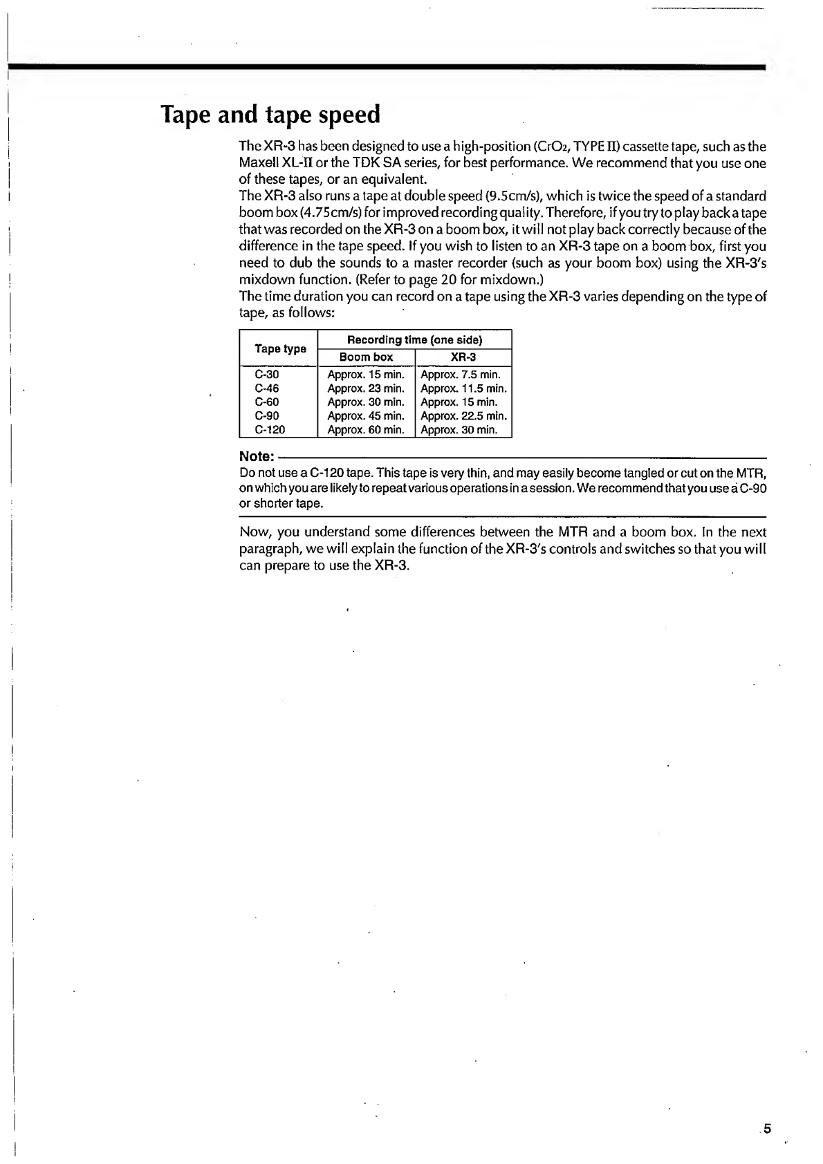
The
time
duration
you
can
record
on
a
tape
using
the
XR-3
varies
depending
on
the
type
of
tape,
as
follows:
Tape
type
Recording
time
(one
side)
Boom
box
XR-3
C-30
Approx.
15
min.
Approx.
7.5
min.
C-46
Approx.
23
min.
Approx.
11.5
min.
C-60
Approx.
30
min.
Approx.
15
min.
C-90
Approx.
45
min.
Approx.
22.5
min.
C-120
Approx.
60
min.
Approx.
30
min.
Note:-
Do
not
use
a
C-120
tape.
This
tape
is
very
thin,
and
may
easily
become
tangled
or
cut
on
the
MTR,
on
which
you
are
likely
to
repeat
various
operations
in
a
session.
We
recommend
that
you
use
a
C-90
or
shorter
tape.
Now,
you
understand
some
differences
between
the
MTR
and
a
boom
box.
In
the
next
paragraph,
we
will
explain
the
function
of
the
XR-3's
controls
and
switches
so
that
you
will
can
prepare
to
use
the
XR-3.
5

The
words
in
square
brackets
[
]
refer
to
the
printing
on
the
front
and
rear
panel.
Control
panel
©
Input
fader
[|T|
El,
El
El
1
This
fader
allows
you
to
adjust
the
recording
level
of
the
musical
instruments
or
external
microphones
connected
to
the
Channel
1,
2
INPUT
jacks,
or
the
recording
level
of
the
internal
microphone.
Raising
the
fader
will
increase
the
recording
level.
The
optimum
recording
level
is
position
7-8,
at
which
the
Level
Meter
will
light
up.
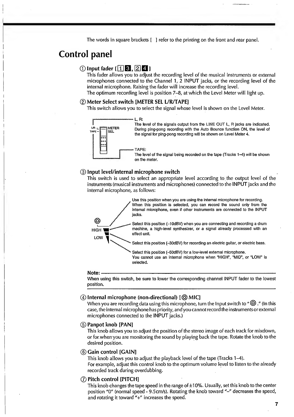
©Meter
Select
switch
[METER
SEL
L/R/TAPE]
This
switch
allows
you
to
select
the
signal
whose
level
is
shown
on
the
Level
Meter.
r
L,
R:
The
level
of
the
signals
output
from
the
LINE
OUT
L,
R
jacks
are
indicated.
During
ping-pong
recording
with
the
Auto
Bounce
function
ON,
the
level
of
the
signal
for
ping-pong
recording
will
be
shown
on
Level
Meter
4.
TAPE:
The
level
of
the
signal
being
recorded
on
the
tape
(Tracks
1-4)
will
be
shown
on
the
meter.
®
Input
Ievel/internal
microphone
switch
This
switch
is
used
to
select
an
appropriate
level
according
to
the
output
level
of
the
instruments
(musical
instruments
and
microphones)
connected
to
the
INPUT
jacks
and
the
internal
microphone,
as
follows:
HIGH
'
LOW
Use
this
position
when
you
are
using
the
internal
microphone
for
recording.
/
When
this
position
is
selected,
you
can
record
the
sound
only
from
the
/
internal
microphone,
even
if
other
instruments
are
connected
to
the
INPUT
/
jacks.
Select
this
position
(-1
OdBV)
when
you
are
connecting
and
recording
a
drum
machine,
a
high-level
synthesizer,
or
a
signal
already
processed
with
an
effect
unit.
^
Select
this
position
(-30dBV)
for
recording
an
electric
guitar,
or
electric
bass.
Select
this
position
(-50dBV)
for
a
low-level
external
microphone.
You
cannot
use
an
internal
microphone
when
“HIGH”,
“MID",
or
“LOW”
is
selected.
Note:-
When
using
this
switch,
be
sure
to
lower
the
corresponding
channel
INPUT
fader
to
the
lowest
position.
©Internal
microphone
(non-directional)
[@MIC]
When
you
are
recording
data
using
this
microphone,
turn
the
Input
switch
to
"
@
(In
this
case,
the
internal
microphone
has
priority,
and
you
cannot
record
the
instruments
or
external
microphones
connected
to
the
INPUT
jacks.)
©
Panpot
knob
[PAN]
This
knob
allows
you
to
adjust
the
position
of
the
stereo
image
of
each
track
for
mixdown,
or
for.
when
you
are
monitoring
the
sound
by
playing
back
the
tape.
Rotate
the
knob
to
the
desired
position.
©
Gain
control
[GAIN]
This
knob
allows
you
to
adjust
the
playback
level
of
the
tape
(Tracks
1-4).
For
example,
adjust
this
control
knob
to
the
optimum
volume
level
to
listen
to
the
already
recorded
track
during
overdubbing.
©Pitch
control
[PITCH]
This
knob
changes
the
tape
speed
in
the
range
of
±10%.
Usually,
set
this
knob
to
the
center
position
"0"
(norma!
speed
-
9.5cm/s).
Rotating
the
knob
toward
decreases
the
speed,
and
rotating
it
toward
"+"
increases
the
speed.
7
CHAPTER
Control
panel
and
front
and
rear
panels
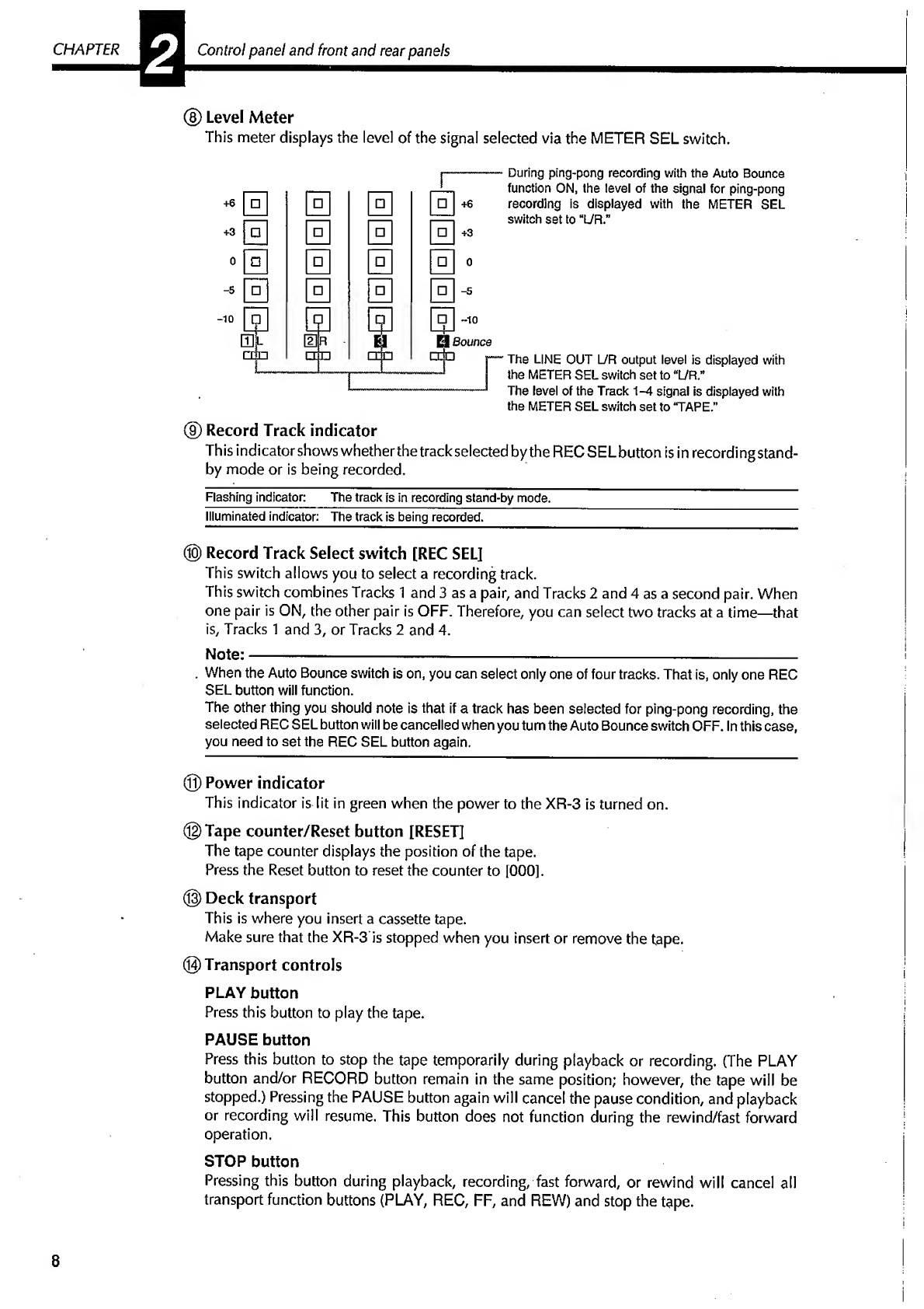
®
Level
Meter
This
meter
displays
the
level
of
the
signal
selected
via
the
METER
SEL
switch.
During
ping-pong
recording
with
the
Auto
Bounce
function
ON,
the
level
of
the
signal
for
ping-pong
recording
is
displayed
with
the
METER
SEL
switch
set
to
“L/R.”
The
LINE
OUT
L/R
output
level
is
displayed
with
the
METER
SEL
switch
set
to
“L/R.”
The
level
of
the
Track
A-A
signal
is
displayed
with
the
METER
SEL
switch
set
to
‘TAPE.”
®
Record
Track
indicator
This
indicator
shows
whetherthe
track
selected
by
the
RECSELbutton
is
in
recording
stand¬
by
mode
or
is
being
recorded.
Flashing
indicator:
The
track
is
in
recording
stand-by
mode.
Illuminated
indicator:
The
track
is
being
recorded.
®
Record
Track
Select
switch
[REC
SEL]
This
switch
allows
you
to
select
a
recording
track.
This
switch
combines
Tracks
1
and
3
as
a
pair,
and
Tracks
2
and
4
as
a
second
pair.
When
one
pair
is
ON,
the
other
pair
is
OFF.
Therefore,
you
can
select
two
tracks
at
a
time—that
is,
Tracks
1
and
3,
or
Tracks
2
and
4.
Note:---
-
-
.
When
the
Auto
Bounce
switch
is
on,
you
can
select
only
one
of
four
tracks.
That
is,
only
one
REC
SEL
button
will
function.
The
other
thing
you
should
note
is
that
if
a
track
has
been
selected
for
ping-pong
recording,
the
selected
REC
SEL
button
will
be
cancelled
when
you
turn
the
Auto
Bounce
switch
OFF.
In
this
case,
you
need
to
set
the
REC
SEL
button
again.
©
Power
indicator
This
indicator
is
lit
in
green
when
the
power
to
the
XR-3
is
turned
on.
©Tape
counter/Reset
button
[RESET]
The
tape
counter
displays
the
position
of
the
tape.
Press
the
Reset
button
to
reset
the
counter
to
[000].
®
Deck
transport
This
is
where
you
insert
a
cassette
tape.
Make
sure
that
the
XR-3
is
stopped
when
you
insert
or
remove
the
tape.
©Transport
controls
PLAY
button
Press
this
button
to
play
the
tape.
PAUSE
button
Press
this
button
to
stop
the
tape
temporarily
during
playback
or
recording.
(The
PLAY
button
and/or
RECORD
button
remain
in
the
same
position;
however,
the
tape
will
be
stopped.)
Pressing
the
PAUSE
button
again
will
cancel
the
pause
condition,
and
playback
or
recording
will
resume.
This
button
does
not
function
during
the
rewind/fast
forward
operation.
STOP
button
Pressing
this
button
during
playback,
recording,
fast
forward,
or
rewind
will
cancel
all
transport
function
buttons
(PLAY,
REC,
FF,
and
REW)
and
stop
the
tape.
8
FF
button
Pressing
this
button
will
fast
forward
the
tape
at
a
high
speed.
REW
button
Pressing
this
button
will
rewind
the
tape
at
a
high
speed.
REC
button
When
any
of
the
Record
Track
indicators
is
flashing,
press
this
button
and
the
PLAY
button
simultaneously
to
start
recording.
(If
the
PAUSE
button
is
on,
the
XR-3
engages
recording
stand-by
mode,
and
the
tape
remains
stopped.)
When
recording
starts,
the
Record
indicator
lights
up,
and
the
Record
Track
indicator
of
the
selected
track
changes
from
flashing
to
lit.
Note:------
This
button
is
not
effective
if
the
record
protect
tub
on
the
cassette
tape
is
broken.
©Record
indicator
[REC]
This
indicator
lights
up
in
red
in
recording
mode.
©Auto
Bounce
Level
dial
[Auto
Bounce
LEVEL]
This
dial
allows
you
to
adjust
the
final
recording
level
of
the
tracks
for
ping-pong
recording.
First,
adjust
the
track
playback
signal
level
using
the
GAIN
control,
then
adjust
the
final
level
of
ping-pong
recording
using
this
dial.
©Auto
Bounce
On/Off
switch
[Auto
Bounce]
This
switch
allows
you
to
turn
the
Auto-bounce
function
(ping-pong)
on/off.
Pressing
this
switch
once
turns
the
function
on,
and
pressing
it
again
turns
the
function
off.
Note:
—----—_
You
cannot
set
this
switch
OFF
during
ping-pong
recording.
©
Auto
Bounce
ON/OFF
indicator
This
indicator
I
ights
up
when
the
Auto
Bounce
switch
is
on,
and
it
goes
off
when
the
switch
is
off.
®
Master
fader
[MASTER]
The
Master
fader
allows
you
to
adjust
the
volume
level
of
the
output
level
at
LINE
OUT
UR
and
the
headphones.
9
CHAPTER
Control
panel
and
front
and
rear
panels
Front
panel
©
Headphone
jack
[PHONESI
Connect
your
headphones
here.
Use
the
MASTER
fader
to
adjust
the
volume
level.
©
Input
jack
[
[T]
0
,
[2]
H
]
Connect
the
musical
instruments
or
external
microphones
here
for
recording.
Be
sure
to
set
the
Input
Level
switch
to
an
appropriate
position
according
to
the
type
of
the
connected
sound
source.
Use
a
standard
1/4"
phone
jack.
©
Punch
In/Out
jack
[PUNCH
IN/OUT]
Connect
an
optional
footswitch
(Model
8051)
here
for
punch
in/out
recording.
Refer
to
page
22
for
a
detailed
explanation
of
punch
in/out
recording.
Rear
panel
©
Tape
Out
jack
[TAPE
OUT
1-4]
These
jacks
output
the
signal
of
Tracks
1-4
to
an
external
mixing
console
or
a
signal
processor.
Jack
4
is
also
used
as
a
SYNC
OUT
jack
to
transmit
a
sync
signal
to
the
connected
MIDI
sequencer
or
drum
machine.
©
Line
Out
jack
[LINE
OUT
L/R]
Connect
these
jacks
to
the
INPUT
jacks
(L,
R)
of
the
master
recorder
for
mixdown.
You
can
also
connect
these
to
speaker
monitors
that
have
a
built-in
amplifier.
Use
the
MASTER
fader
to
adjust
the
output
level.
©
Dolby
B
Noise
Reduction
On/Off
switch
[NR
ON/OFF]
This
switch
allows
you
to
turn
the
Dolby
B
noise
reduction
system
ON/OFF.
In
general,
turn
this
switch
ON
to
achieve
a
higher
recording/playback
sound
quality.
Be
sure
to
turn
this
switch
ON
when
you
are
playing
back
a
tape
recorded
with
Dolby
B
NR.
®
DC
IN
connector
[DC
IN
T77:
12V]
Connect
the
included
AC
adaptor
here.
®
Power
switch
[ON-STANDBY]
This
switch
turns
the
power
ON/OFF
(STANDBY)
to
the
XR-3.
When
the
AC
adaptor
is
connected
to
the
unit
and
the
AC
outlet,
a
small
current
always
exists
in
the
unit
even
if
the
power
switch
is
OFF
(STANDBY).
Therefore,
make
sure
to
remove
the
AC
adaptor
from
the
AC
outlet
if
you
are
not
using
the
XR-3
for
a
long
time
of
period
or
before
you
are
go
out.
10

CHAPTER
■
■
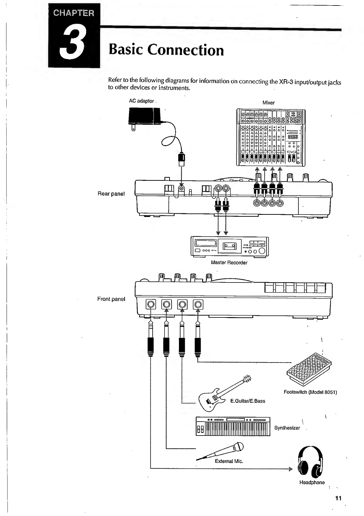
Basic
Guide
"Let's
Start
Recording"
4
Basic
Guide
"Let's
Start
Recording"
i
Initial
setting
of
the
XR-3
You
need
to
organize
all
the
knobs
and
switches
between
steps
or
sessions.
This
means
that
you
will
set
the
position
of
the
switches
and
knobs
to
their
initial
settings
in
order
to
avoid
an
unexpected
problem
that
may
be
caused
by
operating
the
XR-3
with
incorrect
settings.
•These
are
called
the
"initial
settings"
in
this
manual.
The
initial
settings
of
all
switches
and
knobs
are
shown
in
the
following
diagram.
Before
proceeding
to
the
next
session,
be
sure
to
set
the
XR-3
to
the
"initial
settings."
Set
all
the
PAN
controls
to
the
center
position,
and
all
the.GAIN
knobs
to
the
level.
to
OFF.
12
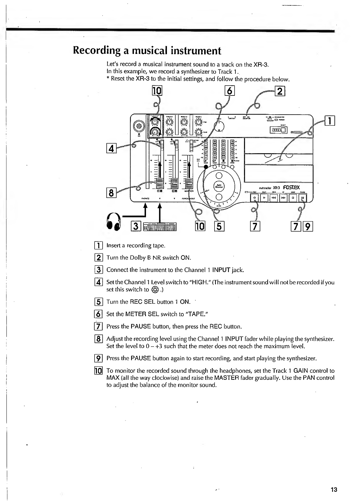
Recording
a
musical
instrument
Let's
record
a
musical
instrument
sound
to
a
track
on
the
XR-3.
In
this
example,
we
record
a
synthesizer
to
Track
1.
*
Reset
the
XR-3
to
the
initial
settings,
and
follow
the
procedure
below.
ffl
Insert
a
recording
tape.
|~2~|
Turn
the
Dolby
B
NR
switch
ON.
3
Connect
the
instrument
to
the
Channel
1
INPUT
jack.
4
Setthe
Channel
1
Level
switch
to
"HIGH."
(The
instrument
sound
will
not
be
recorded
if
you
set
this
switch
to
(§).)
5
Turn
the
REC
SEL
button
1
ON.
[~6~1
Set
the
METER
SEL
switch
to
"TAPE."
|~7~
Press
the
PAUSE
button,
then
press
the
REC
button.
[~8~
Adjust
the
recording
level
using
the
Channel
1
INPUT
fader
while
playing
the
synthesizer.
Set
the
level
to
0
-
+3
such
that
the
meter
does
not
reach
the
maximum
level.
9
Press
the
PAUSE
button
again
to
start
recording,
and
start
playing
the
synthesizer.
m
To
monitor
the
recorded
sound
through
the
headphones,
set
the
Track
1
GAIN
control
to
MAX
(all
the
way
clockwise)
and
raise
the
MASTER
fader
gradually.
Use
the
PAN
control
to
adjust
the
balance
of
the
monitor
sound.
13
CHAPTER
Vi
Basic
Guide
"Let's
Start
Recording"
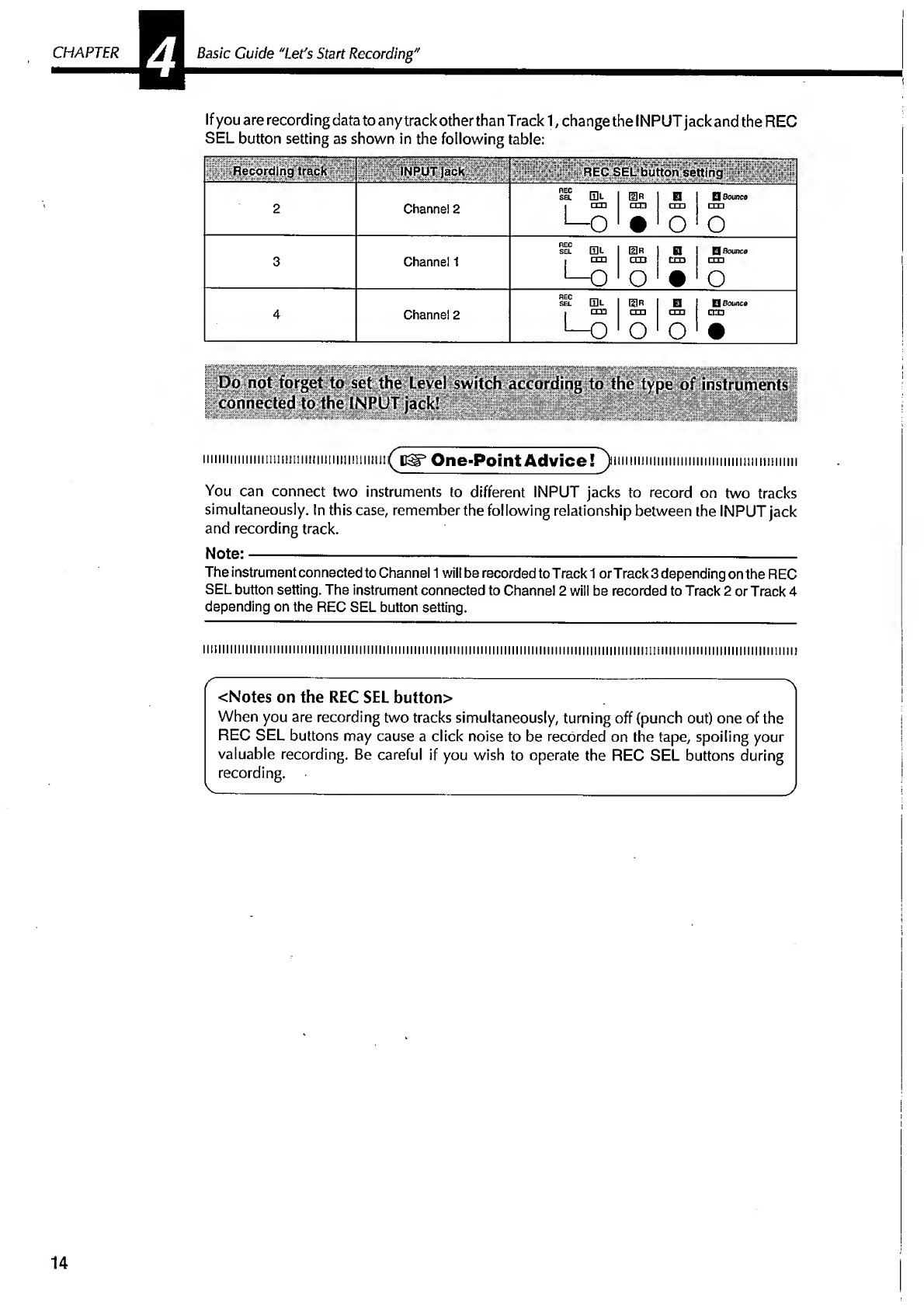
If
you
are
recording
data
to
any
track
other
than
T
rack
1,
change
the
INPUT
jack
and
the
REC
SEL
button
setting
as
shown
in
the
following
table:
Re
co
rdfi
n
g;
UT
;|aic
k
2
REC
SEL
button
setting
REC
i-i,
SB.
0L
[HR
!
0
1
Q
Bounce
Channel
2
i
till
•—
o
cm
•
cm
•
O
1
o
REC
i—i,
SEL
mu
UlR
!
1
H
Q
Bounce
Channel
1
[
cm
'—
O
CCD
|
cm
□
XI
o
1
1
•
o
sel
El
0R
□
D
Bounce
Channel
2
.
cm
L-O
cm
o
cm
o
cro
•
connected
to
the
INPUT
jack!
.iiummmmmmmmimf
usr
One-Point
Advice!
^nimm..
You
can
connect
two
instruments
to
different
INPUT
jacks
to
record
on
two
tracks
simultaneously.
In
this
case,
remember
the
following
relationship
between
the
INPUT
jack
and
recording
track.
The
instrument
connected
to
Channel
1
will
be
recorded
to
T
rack
1
or
Track
3
depending
on
the
REC
SEL
button
setting.
The
instrument
connected
to
Channel
2
will
be
recorded
to
Track
2
or
Track
4
depending
on
the
REC
SEL
button
setting.
<Notes
on
the
REC
SEL
button>
When
you
are
recording
two
tracks
simultaneously,
turning
off
(punch
out)
one
of
the
REC
SEL
buttons
may
cause
a
click
noise
to
be
recorded
on
the
tape,
spoiling
your
valuable
recording.
Be
careful
if
you
wish
to
operate
the
REC
SEL
buttons
during
recording.
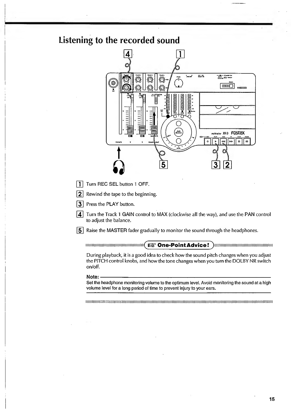
[T]
Turn
REC
SEL
button
1
OFF.
[2]
Rewind
the
tape
to
the
beginning.
|~3]
Press
the
PLAY
button.
[
4
]
Turn
the
Track
1
GAIN
control
to
MAX
(clockwise
all
the
way),
and
use
the
PAN
control
to
adjust
the
balance.
5
Raise
the
MASTER
fader
gradually
to
monitor
the
sound
through
the
headphones.
iiniiiHiiiinniiiiiiiiiiiiiiiiininiimmi
^pdi^
One-Point
Advice?
^
)i
t
m
11
m
111
m
1111111
m
1
m
11111
m
1
h
1111
n
1
During
playback,
it
is
a
good
idea
to
check
how
the
sound
pitch
changes
when
you
adjust
the
PITCH
control
knobs,
and
how
the
tone
changes
when
you
turn
the
DOLBY
NR
switch
on/off.
Note:-
Set
the
headphone
monitoring
volume
to
the
optimum
level.
Avoid
monitoring
the
sound
at
a
high
volume
level
for
a
long
period
of
time
to
prevent
injury
to
your
ears.
iiiiiiiiiiiiiniimiimimiiimimi
iiiiitiiiiiiiiiiiiiiiiiiiiMiiiiiiiiiiiiiiiiiiiiiiiiiiiiiiiiiiiiiiiiiiiiiiiiiiiiiiiiiiiiiiiiiiiiiiiiiiiiimiiii
15
CHAPTER
4
Basic
Guide
"Let's
Start
Recording"
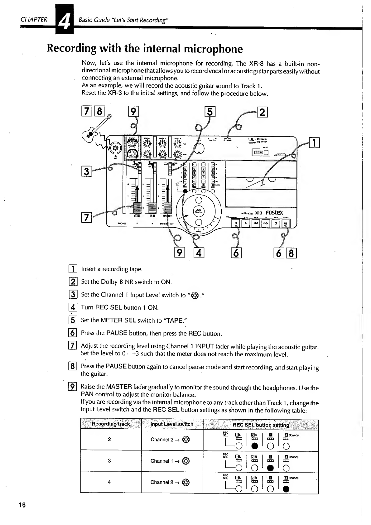
Recording
with
the
internal
microphone
Now,
let's
use
the
internal
microphone
for
recording.
The
XR-3
has
a
built-in
non-
directional
microphone
that
allows
you
to
record
vocal
or
acoustic
guitar
parts
easily
without
connecting
an
external
microphone.
As
an
example,
we
wilt
record
the
acoustic
guitar
sound
to
Track
1.
Reset
the
XR-3
to
the
initial
settings,
and
follow
the
procedure
below.
ffl
Insert
a
recording
tape.
[21
Set
the
Dolby
B
NR
switch
to
ON.
ID
Set
the
Channel
1
Input
Level
switch
to
."
[
4
]
Turn
REC
SEL
button
1
ON.
[5]
Set
the
METER
SEL
switch
to
"TAPE."
|~
6
~
Press
the
PAUSE
button,
then
press
the
REC
button.
I~7~
Adjust
the
recording
level
using
Channel
1
INPUT
fader
while
playing
the
acoustic
guitar.
Set
the
level
to
0
-
+3
such
that
the
meter
does
not
reach
the
maximum
level.
8J
Press
the
PAUSE
button
again
to
cancel
pause
mode
and
start
recording,
and
start
playing
the
guitar.
9
Raise
the
MASTER
fader
gradually
to
monitor
the
sound
through
the
headphones.
Use
the
PAN
control
to
adjust
the
monitor
balance.
If
you
are
recording
via
the
internal
microphone
to
any
track
other
than
Track
1,
change
the
Input
Level
switch
and
the
REC
SEL
button
settings
as
shown
in
the
following
table:
Recording
track
Input
Level
switch
REC
SEL
button
setting
.
REC
~
SEL
Q]L
0
R
El
Q
Bounce
2
Channel
2
->
@
|
ITT)
ca
1
cm
CTD
L
0
•
0
0
REC
1—1
SEL
Q]L
•
0
R
0
□
Bounce
3
Channel
1
-»
1
cm
n.
1
1
cm
>—0
O
•
0
HEC
SEL
01-
0
Q
Bounce
4
Channel
2
@
1
cm
rm
cm
-
O
O
0
•
1
I
16
iiiiiiiiiiiiiiiiiiiiiiiiiiiiiiiiiiiiiiiimiiiii
^tt^
One-Point
AdviceTj
iiiiiiiiiiiiiiiiHiiiiniiiiiiiiiiiimiiimiii
As
we
explained
in
the
previous
synthesizer
recording
session,
you
can
also
record
on
two
tracks
simultaneously
by
switching
the
source
for
Channels
1
and
2
to
the
internal
microphone
and
assigning
recording
tracks.
111111111
i
f
I!
H!
11
n
111
i
i
IJ1!
111)
111
i
111111111111J111111J11111111111111111111111111111111111111111111
((f
{|
j
j
11111111111111
,|
|
,|
11,
f
|
j
in
j
|
m
m
m
1111
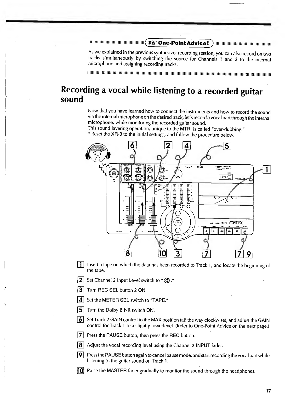
Recording
a
vocal
while
listening
to
a
recorded
guitar
sound
Now
that
you
have
learned
how
to
connect
the
instruments
and
how
to
record
the
sound
via
the
internal
microphone
on
the
desired
track,
let's
record
a
vocal
partthrough
the
internal
microphone,
while
monitoring
the
recorded
guitar
sound.
This
sound
layering
operation,
unique
to
the
MTR,
is
called
"over-dubbing."
*
Reset
the
XR-3
to
the
initial
settings,
and
follow
the
procedure
below.
ITI
insert
a
tape
on
which
the
data
has
been
recorded
to
Track
1,
and
locate
the
beginning
of
the
tape.
2
Set
Channel
2
Input
Level
switch
to
."
j~3~l
Turn
REC
SEL
button
2
ON.
[4~|
Set
the
METER
SEL
switch
to
"TAPE."
[51
Turn
the
Dolby
B
NR
switch
ON.
6
Set
Track
2
GAIN
control
to
the
MAX
position
(all
the
way
clockwise),
and
adjust
the
GAIN
control
for
Track
1
to
a
slightly
lowerlevel.
(Refer
to
One-Point
Advice
on
the
next
page.)
|~7~
Press
the
PAUSE
button,
then
press
the
REC
button.
[8~
Adjust
the
vocal
recording
level
using
the
Channel
2
INPUT
fader.
9
Press
the
PAUSE
button
again
to
cancel
pause
mode,
and
start
recording
the
vocal
part
while
listening
to
the
guitar
sound
on
Track
1.
10
Raise
the
MASTER
fader
gradually
to
monitor
the
sound
through
the
headphones.
17
CHAPTER
Vi
Basic
Guide
"Let's
Start
Recording"
iuiHiiiiiiiiiiiiiiiiiiiiiiiiiiiiiiiiiiiiiiiiii
^
pjir*
One-Point
Advice!
J
iiiiiiiiimiiimimiiiiiiiiiiiiiiiiiiiiiiiiii
It
is
a
good
idea
to
set
the
PAN
controls
to
L
or
R
separately
for
each
track.
This
will
separate
the
playback
sound
and
recording
sound
clearly
for
easier
monitoring
through
the
head¬
phones.
If
you
set
all
the
PAN
controls
to
the
center
position,
these
two
sounds
are
combined.
Try
various
settings.
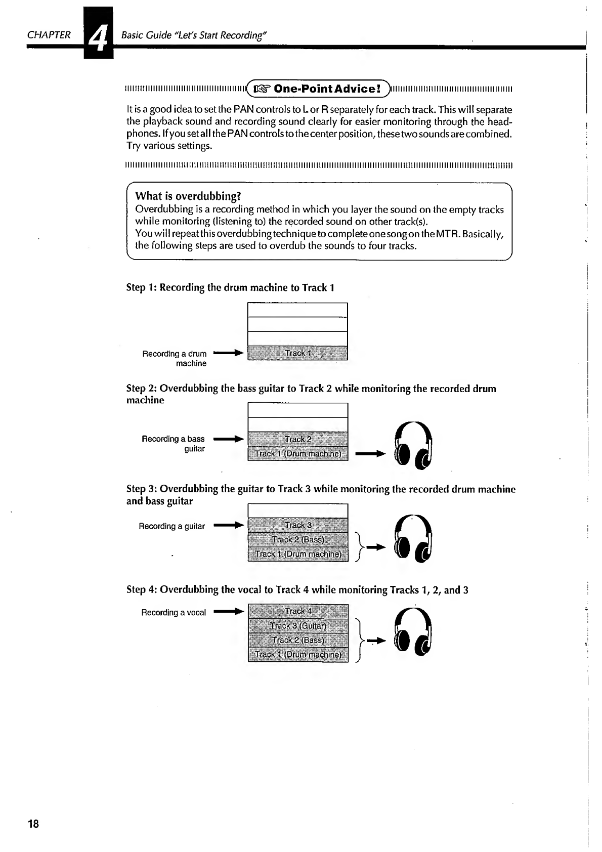
What
is
overdubbing?
Overdubbing
is
a
recording
method
in
which
you
layer
the
sound
on
the
empty
tracks
while
monitoring
(listening
to)
the
recorded
sound
on
other
track(s).
You
will
repeatthisoverdubbingtechnique
to
complete
one
song
on
the
MTR.
Basically,
the
following
steps
are
used
to
overdub
the
sounds
to
four
tracks.
Step
1:
Recording
the
drum
machine
to
Track
1
Recording
a
drum
machine
Step
2:
Overdubbing
the
bass
guitar
to
Track
2
while
monitoring
the
recorded
drum
machine
__.
Recording
a
bass
guitar
!S!Ht£
d
lll!:
Track
1
(Drum
machine)
|
0
Step
3:
Overdubbing
the
guitar
to
Track
3
while
monitoring
the
recorded
drum
machine
and
bass
guitar
,-
Recording
a
guitar
Track
3
HlpigtBaaill
Track
1
(Drum
machine)
Step
4:
Overdubbing
the
vocal
to
Track
4
while
monitoring
Tracks
1,
2,
and
3
Recording
a
vocal
Track
4
^Track
2
(Base)
Track
TfDrum
machine)
Q
18

The
following
table
shows
the
settings
of
the
INPUT
jacks,
Input
Level
switches,
the
REC
SEL
buttons,
and
GAIN
and
PAN
controls
during
the
basic
overdubbing
operation
(Step
1
-Step
4).
Refer
to
this
table
for
Step
1-4
operation.
INPUT
jack
Input
Level
switch
GAIN
and
PAN
(Monitor
section)
Step
1
Channel
1
Channel
1
-»
HIGH
SEL
CQl
I
[3
n.
1
21
1
Hsoooco
r
on
cm
j
rrn
OH
1
O
1
O
1
0
Step
2
Channel
2
Channel
2
->
MID
SEt
0L
1
CO
A
1
D
1
QSouncd
I
cm
J
cm
rm
m3
•—
o
1
•
1
o
1
o
Step
3
Channel
1
Channel
1
-»
M
ID
SEL
tDL
1
Efi
I
D
1
□
flounce
1
■
■
■
■
1
■
»
■
i
1
rrn
1
1111
1
0
1
•
1
o
Step
4
Channel
2
Channel
2
-»@
/'Set
this
switch
to
“LOWn
when
you
are
using
an
V.
external
microphone.
J
SEL
Ql
I
0R
f
fl
1
QBrXmce
i
cm
cm
cm
am
o
1
o
1
o
1
•
TRACK
1
TRACK
2
TRACK
3
TRACK
4
L^R
U
\\
l
—
n
iimiimiiiiiimimiimiiiiimmiimm
^
i
Bg*
One-Point
Advice
1
ii
n
n
imiiiiiiniiiiiiiii
Be
careful
when
you
are
setting
the
REC
SEL
buttons
for
the
overdubbing
steps.
One
incorrect
setting
may
destroy
your
efforts.
mmmmiiimiiiiiiiiiiiiiiiimuiiiimn
^c^^
One«Point
AdvicesT
)
i
iiiiiii
i
m
i
i
ii
t
i
ii
i
m
iiiiiii
m
iiii
mmm
The
settings
of
the
monitor
section
(GAIN
&
PAN)
shown
in
the
table
above
are
just
an
example.
You
can
set
the
playback
level
lower,
and
the
recording
level
higher.
You
can
also
pan
all
sounds
to
the
center
for
monitoring.
Adjust
the
GAIN
and
PAN
controls
to
suit
your
taste.
Listening
to
the
recorded
tracks
When
you
finish
recording
the
song
to
the
tracks,
let's
listen
to
the
result.
IT!
Rewind
the
tape
to
the
beginning.
|~2~1
Turn
alt
the
REC
SEL
buttons
OFF.
3
4
5
6
Set
the
METER
SEL
switch
to
"L/R."
Press
the
PLAY
button
to
start
playback.
Adjust
the
track
volume
level
and
balance
using
the
Track
1-4
GAIN
control
and
PAN
control,
respectively.
Raise
the
MASTER
fader
gradually,
and
you
will
hear
the
sound
of
each
track.
19

CHAPTER
*1
Basic
Guide
"Let's
Start
Recording"
Mixdown
Now
that
you
have
finished
recording
the
sounds
to
Tracks
1-4,
we
will
mix
the
sounds
of
these
four
tracks
and
record
them
onto
the
master
recorder
in
stereo.
This
step
is
called
"mixdown."
After
mixdown,
you
can
playback
the
recorded
tape
on
a
boom
box.
First;
reset
the
XR-3
to
the
initial
settings.
!iiiiiiiiiiiiiiiiiii!ii!iiiiiiiii!iiiiiiiii!iii(
uSr*
One-Point
Advice!
)
iiiiiiiiimiiiiiiiiiiimmiiiiiiiiimmm
The
use
of
the
PAN
controls
is
different
from
that
in
overdubbing.
In
mixdown,
the
sounds
of
the
four
tracks
are
mixed
in
stereo.
Use
the
PAN
control
of
each
track
to
set
the
desired
stereo
image.
Refer
to
the
following
settings
example:
Track
Type
of
musical
instrument
Track
1
Drum
machine
Track
2
Bass
guitar
Track
3
Electric
guitar
(or
synth)
Track
4
Vocal
PANcoitvfrbrpositiqhl
Center
Connections
|~1~|
Connect
the
LINE
OUT
L,
R
jacks
and
the
master
recorder
INPUT
jacks.
[2]
Set
the
METER
SEL
switch
to
"L/R."
Rehearsal
3
Press
the
PAUSE
button
and
REC
button
on
the
master
recorder
to
place
the
recorder
in
REC-PAUSE
mode.
[41
While
playing
back
the
tape,
adjust
the
track
playback
level
and
balance
using
the
track
GAIN
control
and
PAN
control
respectively,
and
adjust
the
overall
level
of
the
signal
output
from
LINE
OUT
L,
R
using
the
MASTER
fader.
(Check
the
level
with
the
meter.)
At
this
time,
check
the
input
level
on
the
master
recorder.
20
Other manuals for XR-3
1
Table of contents
Other Fostex Recording Equipment manuals

Fostex
Fostex MTC1 User manual

Fostex
Fostex VF-160 User manual

Fostex
Fostex CR500 User manual

Fostex
Fostex DV-824 User manual

Fostex
Fostex DV-824 Configuration guide

Fostex
Fostex D2424LV MKII User manual

Fostex
Fostex 8346 User manual

Fostex
Fostex PD606 User manual

Fostex
Fostex D-90 User manual

Fostex
Fostex VF160EX User manual

Fostex
Fostex M80 User manual

Fostex
Fostex DE-1 User manual

Fostex
Fostex VR800 User manual

Fostex
Fostex MR-16HD Instructions and recipes

Fostex
Fostex VF-08 User manual

Fostex
Fostex XR-3 User manual

Fostex
Fostex VF-16 Manual

Fostex
Fostex MR-8MKII User manual

Fostex
Fostex VF-16 User manual

Fostex
Fostex DV-40 User manual


