manuals.online logo
Brands
  1. Home
  2. •
  3. Brands
  4. •
  5. Danfoss
  6. •
  7. DC Drive
  8. •
  9. Danfoss VLT Flow Drive FC 111 Guide

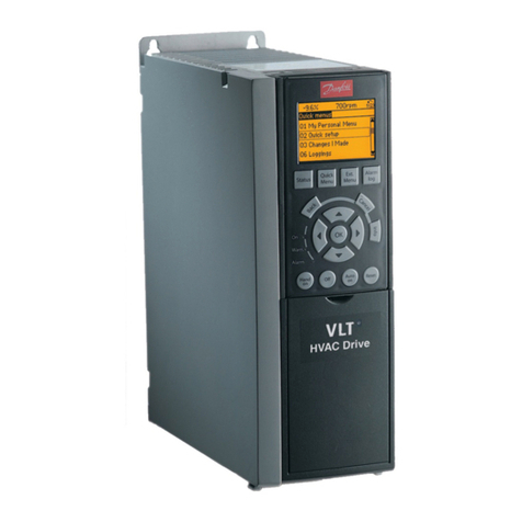
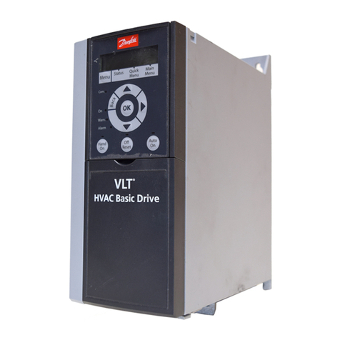
Danfoss VLT Flow Drive FC 111 Guide

Other manuals for VLT Flow Drive FC 111

1

Other Danfoss DC Drive manuals

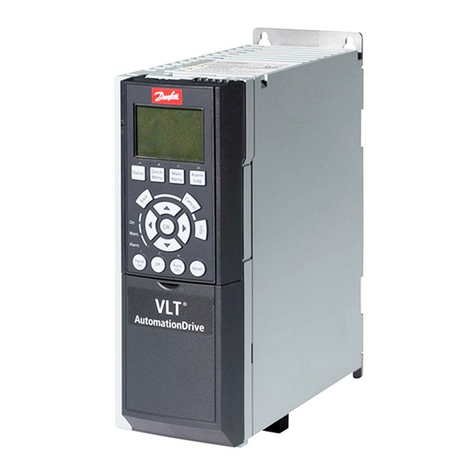
Danfoss VLT Automation Drive FC 300 User manual

Danfoss

Danfoss VLT Automation Drive FC 300 User manual

Danfoss VLT AutomationDrive FC 300 Guide

Danfoss

Danfoss VLT AutomationDrive FC 300 Guide

Danfoss VLT FC Series User manual

Danfoss

Danfoss VLT FC Series User manual

Danfoss VLT MSD 510 User manual

Danfoss

Danfoss VLT MSD 510 User manual

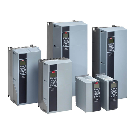
Danfoss VLT HVAC FC 100 User manual

Danfoss

Danfoss VLT HVAC FC 100 User manual

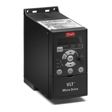
Danfoss VLT Micro Drive FC 51 Series Operating instructions

Danfoss

Danfoss VLT Micro Drive FC 51 Series Operating instructions

Danfoss Holip HLP-V Series User manual

Danfoss

Danfoss Holip HLP-V Series User manual

Danfoss VLT FC 300 User manual

Danfoss

Danfoss VLT FC 300 User manual

Danfoss VLT Midi Drive FC 280 Operating instructions

Danfoss

Danfoss VLT Midi Drive FC 280 Operating instructions

Danfoss VLT AutomationDrive FC 302 User manual

Danfoss

Danfoss VLT AutomationDrive FC 302 User manual

Danfoss VLT AutomationDrive FC 300 Operating instructions

Danfoss

Danfoss VLT AutomationDrive FC 300 Operating instructions

Danfoss VLT HVAC Basic Drive FC 101 Guide

Danfoss

Danfoss VLT HVAC Basic Drive FC 101 Guide

Danfoss VLT AQUA Drive FC 202 User manual

Danfoss

Danfoss VLT AQUA Drive FC 202 User manual

Danfoss VLT AQUA Drive FC 202 User manual

Danfoss

Danfoss VLT AQUA Drive FC 202 User manual

Danfoss VLT 2800 User manual

Danfoss

Danfoss VLT 2800 User manual

Danfoss VLT DriveMotor FCP 106 Guide

Danfoss

Danfoss VLT DriveMotor FCP 106 Guide

Danfoss FC 100 Series User manual

Danfoss

Danfoss FC 100 Series User manual

Danfoss VLT CDS 803 User manual

Danfoss

Danfoss VLT CDS 803 User manual

Danfoss AKD 2800 Specification sheet

Danfoss

Danfoss AKD 2800 Specification sheet

Danfoss VLT AQUA Drive FC 200 User manual

Danfoss

Danfoss VLT AQUA Drive FC 200 User manual

Danfoss AME 23 User manual

Danfoss

Danfoss AME 23 User manual

Danfoss VLT FC 103 Guide

Danfoss

Danfoss VLT FC 103 Guide

Danfoss vlt fcd 302 User manual

Danfoss

Danfoss vlt fcd 302 User manual

Danfoss VLT AutomationDrive FC 300 User manual

Danfoss

Danfoss VLT AutomationDrive FC 300 User manual

Popular DC Drive manuals by other brands

National Instruments NI MID-7604 user guide

National Instruments

National Instruments NI MID-7604 user guide

SOMFY Maestria WT Series instructions

SOMFY

SOMFY Maestria WT Series instructions

Trane TR150 Service manual

Trane

Trane TR150 Service manual

Chamberlain Garog D Series operating manual

Chamberlain Garog

Chamberlain Garog D Series operating manual

Parker PDS Series user guide

Parker

Parker PDS Series user guide

Binks QS-5012-1-CE Service manual

Binks

Binks QS-5012-1-CE Service manual

YASKAWA CANopen SI-S3 Technical manual

YASKAWA

YASKAWA CANopen SI-S3 Technical manual

GE D20A6 instructions

GE

GE D20A6 instructions

Lenze PositionServo 940 user manual

Lenze

Lenze PositionServo 940 user manual

Unex MC-D-250-1000-050W-TW operating manual

Unex

Unex MC-D-250-1000-050W-TW operating manual

Geckodrive G213V manual

Geckodrive

Geckodrive G213V manual

ABB RSYC-01 user manual

ABB

ABB RSYC-01 user manual

Rockwell Automation PowerFlex 700S Programming manual

Rockwell Automation

Rockwell Automation PowerFlex 700S Programming manual

WEG DeviceNet CFW500 user manual

WEG

WEG DeviceNet CFW500 user manual

Siemens SINAMICS G List manual

Siemens

Siemens SINAMICS G List manual

Siemens SINAMICS SM150 6SL3815-7NP41-0AA1 Operating instructions & installation instructions

Siemens

Siemens SINAMICS SM150 6SL3815-7NP41-0AA1 Operating instructions & installation instructions

SOMFY JR RU 30 instructions

SOMFY

SOMFY JR RU 30 instructions

Beckhoff AX8911 Documentation

Beckhoff

Beckhoff AX8911 Documentation

manuals.online logo
manuals.online logoBrands
  • About & Mission
  • Contact us
  • Privacy Policy
  • Terms and Conditions

Copyright 2025 Manuals.Online. All Rights Reserved.

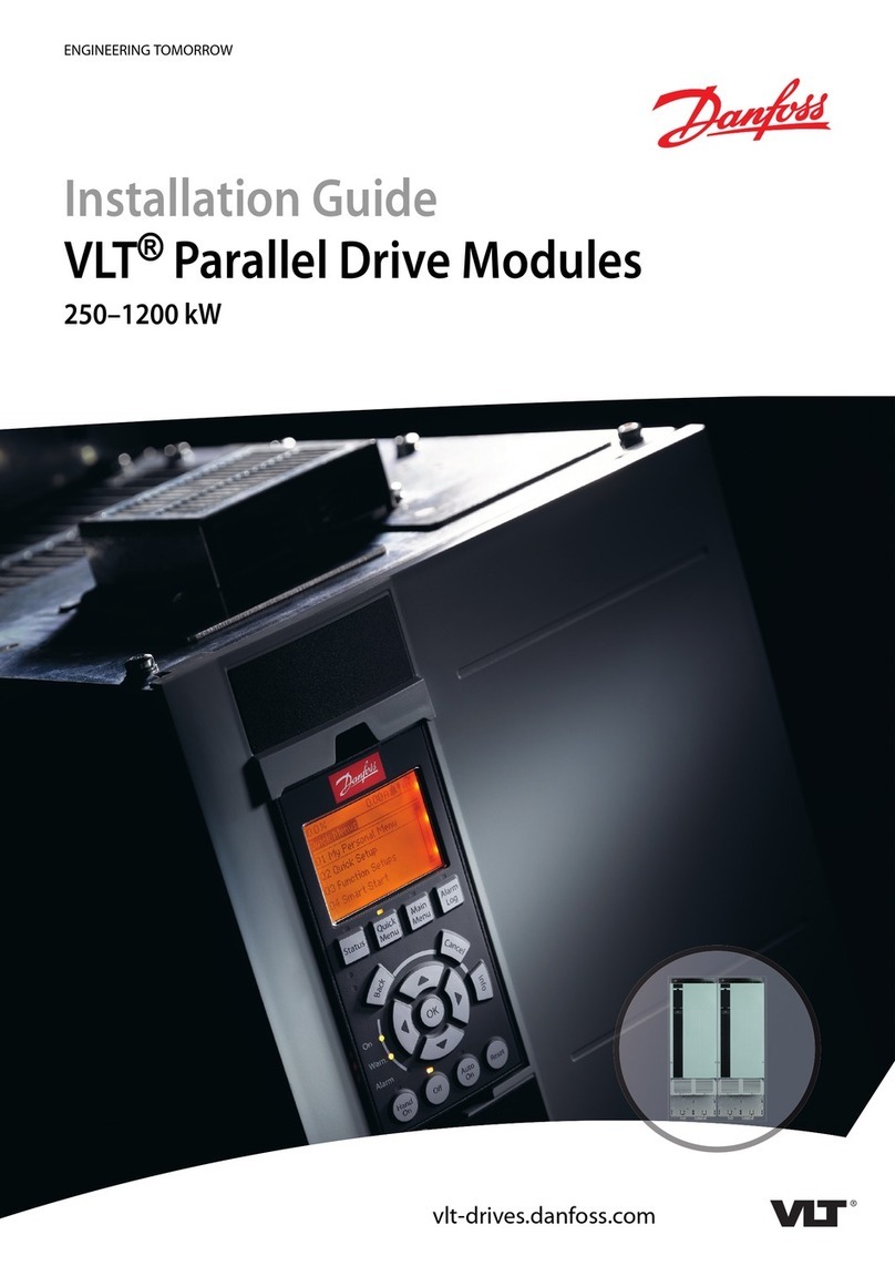
Design Guide
VLT® Flow Drive FC 111
vlt-drives.danfoss.com
1
1.1
1.2
1.2.1
1.2.2
1.3
1.4
1.4.1
1.4.2
2
2.1
2.2
2.3
3
3.1
3.1.1
3.1.1.1
3.1.1.2
3.1.1.3
3.1.1.4
3.1.1.5
3.1.1.6
3.1.1.7
3.1.1.8
3.1.1.9
3.1.2
3.1.2.1
3.1.2.2
3.1.2.3
3.1.2.4
3.1.2.5
3.1.2.6
3.1.3
3.1.4
3.1.5
Contents
Introduction 10
Purpose of this Design Guide 10
Additional Resources 10
Other Resources 10
MCT 10 Set-up Software Support 10
Document and Software Version 10
Regulatory Compliance 10
Introduction 10
CE Mark 10
Safety 12
Safety Symbols 12
Qualified Personnel 12
Safety Precautions 12
Product Overview 14
Advantages 14
Why Use a Drive for Controlling Fans and Pumps? 14
The Clear Advantage - Energy Savings 14
Example of Energy Savings 15
Comparison of Energy Savings 15
Example with Varying Flow over 1 Year 17
Better Control 18
Star/Delta Starter or Soft Starter not Required 18
Using a Drive Saves Money 18
Traditional Fan System without a Drive 19
Fan System Controlled by Drives 20
Application Examples 20
Variable Air Volume 20
Constant Air Volume 21
Cooling Tower Fan 22
Condenser Pumps 23
Primary Pumps 24
Secondary Pumps 25
Check Valve Monitoring 26
Dry Pump Detection 26
End of Curve Detection 26
AJ363928382091en-000101/130R0983 | 3Danfoss A/S © 2021.04
Contents
VLT® Flow Drive FC 111
Design Guide
3.1.6
3.2
3.2.1
3.2.2
3.2.3
3.2.4
3.2.5
3.2.6
3.2.7
3.2.8
3.2.9
3.3
3.3.1
3.3.2
3.3.2.1
3.3.2.2
3.3.3
3.4
3.4.1
3.4.2
3.4.3
3.4.4
3.4.4.1
3.4.4.2
3.4.5
3.4.6
3.4.7
3.5
3.6
3.6.1
3.7
3.7.1
3.7.2
3.7.3
3.7.3.1
3.7.3.2
Time-based Functions 26
Control Structures 26
Introduction 26
Control Structure Open Loop 27
PM/EC+ Motor Control 27
Local (Hand On) and Remote (Auto On) Control 27
Control Structure Closed Loop 28
Feedback Conversion 28
Reference Handling 28
Tuning the Drive Closed-loop 29
Adjusting the Manual PI 29
Ambient Running Conditions 30
Air Humidity 30
Acoustic Noise or Vibration 30
Acoustic Noise 30
Vibration and Shock 31
Aggressive Environments 31
General Aspects of EMC 31
Overview of EMC Emissions 31
Emission Requirements 32
EMC Emission Test Results 33
Harmonics Emission 34
Harmonics Emission Requirements 34
Harmonics Test Results (Emission) 35
Harmonics Emission Requirements 34
Harmonics Test Results (Emission) 36
Immunity Requirements 37
Galvanic Isolation (PELV) 37
Ground Leakage Current 38
Using a Residual Current Device (RCD) 40
Extreme Running Conditions 41
Introduction 41
Motor Thermal Protection (ETR) 42
Thermistor Inputs 42
Example with Digital Input and 10 V Power Supply 43
Example with Analog Input and 10 V Power Supply 43
AJ363928382091en-000101/130R09834 | Danfoss A/S © 2021.04
Contents
VLT® Flow Drive FC 111
Design Guide
4
4.1
4.2
4.2.1
4.2.2
4.2.3
4.3
4.3.1
4.3.2
4.3.3
5
5.1
5.2
5.2.1
5.3
5.3.1
5.3.2
5.3.3
5.3.4
5.3.5
5.3.6
5.4
5.4.1
5.4.2
5.4.3
5.4.4
6
6.1
6.2
6.3
6.4
6.4.1
6.4.2
6.4.3
6.4.4
6.4.5
6.5
Selection and Ordering 45
Type Code 45
Options and Accessories 46
Local Control Panel (LCP) 46
IP21 Enclosure Kit 46
Decoupling Plate 48
Ordering Numbers 49
Options and Accessories 49
Harmonic Filters 50
External RFI Filter 51
Mechanical Installation Considerations 53
Power Ratings, Weights, and Dimensions 53
Mechanical Installation H1-H8 55
Side-by-side Installation 55
Mechanical Installation H13-H14 56
Tools Needed 56
Installation and Cooling Requirements 56
Lifting the Drive 57
Wall Mounting the Drive 58
Creating Cable Openings 59
Back-channel Cooling 59
Derating 60
Manual Derating and Automatic Derating 60
Derating for Low-speed Operation 60
Derating for Low Air Pressure and High Altitudes 60
Derating for Ambient Temperature and Switching Frequency 60
Electrical Installation Considerations 63
Safety Instructions 63
Electrical Wiring 64
EMC-compliant Electrical Installation 64
Relays and Terminals 66
Relays and Terminals on Enclosure Sizes H1–H5 66
Relays and Terminals on Enclosure Size H6 67
Relays and Terminals on Enclosure Size H7 67
Relays and Terminals on Enclosure Size H8 68
Relays and Terminals on Enclosure Size H13–H14 69
View of Control Shelf 69
AJ363928382091en-000101/130R0983 | 5Danfoss A/S © 2021.04
Contents
VLT® Flow Drive FC 111
Design Guide
6.6
6.7
6.8
6.8.1
6.8.2
6.8.3
6.8.4
6.9
6.9.1
6.9.2
6.9.3
6.9.4
6.9.5
6.10
6.11
6.11.1
6.11.2
6.11.3
6.12
6.12.1
6.12.2
6.12.3
6.12.4
7
7.1
7.2
7.2.1
7.2.2
7.2.2.1
7.2.2.2
7.2.2.3
7.2.2.4
7.2.2.5
7.2.2.6
7.2.2.7
7.2.2.8
7.2.3
Fastener Tightening Torques 70
IT Mains 71
Mains and Motor Connection 72
Introduction 72
Connecting to the Ground 72
Connecting the Motor 73
Connecting the AC Mains 73
Fuses and Circuit Breakers 73
Branch Circuit Protection 73
Short-circuit Protection 73
Overcurrent Protection 74
CE Compliance 74
Recommendation of Fuses and Circuit Breakers 74
Control Terminals 75
Efficiency 76
Efficiency of the Drive 76
Efficiency of the Motor 77
Efficiency of the System 77
dU/dt Conditions 77
dU/dt Overview 77
dU/dt Test Results for H1–H8 77
High-power Range 80
dU/dt Test Results for H13–H14 80
Programming 81
Local Control Panel (LCP) 81
Menus 82
Status Menu 82
Quick Menu 82
Quick Menu Introduction 82
Setup Wizard Introduction 83
Setup Wizard for Open-loop Applications 84
Setup Wizard for Closed-loop Applications 89
Motor Setup 94
Changes Made Function 97
Changing Parameter Settings 98
Accessing All Parameters via the Main Menu 98
Main Menu 98
AJ363928382091en-000101/130R09836 | Danfoss A/S © 2021.04
Contents
VLT® Flow Drive FC 111
Design Guide
7.3
7.3.1
7.3.2
7.4
7.5
7.5.1
7.5.2
8
8.1
8.1.1
8.1.2
8.1.3
8.1.4
8.1.5
8.2
8.2.1
8.2.2
8.3
8.4
8.4.1
8.4.2
8.4.3
8.4.4
8.4.5
8.4.6
8.4.7
8.4.8
8.4.9
8.4.10
8.4.11
8.4.12
8.4.13
8.5
8.5.1
8.5.2
8.6
8.6.1
Quick Transfer of Parameter Settings between Multiple Drives 98
Transferring Data from the Drive to the LCP 98
Transferring Data from the LCP to the Drive 98
Readout and Programming of Indexed Parameters 99
Initialization to Default Settings 99
Recommended Initialization 99
Two-finger Initialization 99
RS485 Installation and Set-up 101
RS485 101
Overview 101
Connecting the Drive to the RS485 Network 102
Hardware Set-up 102
Parameter Settings for Modbus Communication 103
EMC Precautions 103
FC Protocol 104
Overview 104
FC with Modbus RTU 104
Network Configuration 105
FC Protocol Message Framing Structure 105
Content of a Character (byte) 105
Telegram Structure 105
Telegram Length (LGE) 105
Drive Address (ADR) 106
Data Control Byte (BCC) 106
The Data Field 106
The PKE Field 107
Parameter Number (PNU) 108
Index (IND) 108
Parameter Value (PWE) 108
Data Types Supported by the Drive 109
Conversion 109
Process Words (PCD) 110
Examples 110
Writing a Parameter Value 110
Reading a Parameter Value 110
Modbus RTU 111
Prerequisite Knowledge 111
AJ363928382091en-000101/130R0983 | 7Danfoss A/S © 2021.04
Contents
VLT® Flow Drive FC 111
Design Guide
8.6.2
8.6.3
8.7
8.8
8.8.1
8.8.2
8.8.3
8.8.4
8.8.5
8.8.6
8.8.7
8.8.8
8.8.8.1
8.8.8.2
8.8.8.3
8.8.8.4
8.8.8.5
8.8.9
8.8.10
8.8.10.1
8.8.10.2
8.8.10.3
8.9
8.9.1
8.9.2
8.9.3
8.9.4
8.9.5
8.9.6
8.10
8.10.1
8.10.2
8.10.3
8.10.4
8.10.5
8.10.6
8.10.7
8.10.8
Modbus RTU Overview 111
Drive with Modbus RTU 111
Network Configuration 112
Modbus RTU Message Framing Structure 112
Modbus RTU Message Byte Format 112
Modbus RTU Telegram Structure 113
Start/Stop Field 113
Address Field 113
Function Field 113
Data Field 113
CRC Check Field 113
Coil Register Addressing 114
Introduction 114
Coil Register 114
Drive Control Word (FC Profile) 114
Drive Status Word (FC Profile) 115
Address/Registers 115
Access via PCD Write/read 116
How to Control the Drive 117
Introduction 117
Function Codes Supported by Modbus RTU 117
Modbus Exception Codes 118
How to Access Parameters 118
Parameter Handling 118
Storage of Data 118
IND (Index) 119
Text Blocks 119
Conversion Factor 119
Parameter Values 119
Examples 119
Introduction 119
Read Coil Status (01 hex) 119
Force/Write Single Coil (05 hex) 120
Force/Write Multiple Coils (0F hex) 121
Read Holding Registers (03 hex) 122
Preset Single Register (06 hex) 122
Preset Multiple Registers (10 hex) 123
Read/Write Multiple Registers (17 hex) 124
AJ363928382091en-000101/130R09838 | Danfoss A/S © 2021.04
Contents
VLT® Flow Drive FC 111
Design Guide
8.11
8.11.1
8.11.2
8.11.3
8.11.4
8.11.5
9
9.1
9.1.1
9.2
9.2.1
9.2.2
9.2.3
9.2.4
9.2.5
9.2.6
9.2.7
9.2.8
9.2.9
9.2.10
9.2.11
9.2.12
9.2.13
9.2.14
10
10.1
10.2
10.2.1
10.2.2
10.2.3
10.2.4
10.2.5
Danfoss FC Control Profile 125
Control Word According to FC Profile (8-10 Protocol = FC Profile) 125
Explanation of Each Control Bit 126
Status Word According to FC Profile (STW) 128
Explanation of Each Status Bit 128
Bus Speed Reference Value 130
General Specifications 131
Mains Supply 131
3x380–480 V AC 131
General Technical Data 133
Protection and Features 133
Mains Supply 133
Motor Output (U, V, W) 133
Cable Length and Cross-section 134
Digital Inputs 134
Analog Inputs 134
Analog Outputs 135
Digital Output 135
RS485 Serial Communication 135
24 V DC Output 135
Relay Output 135
10 V DC Output 136
Ambient Conditions (H1–H8) 136
Ambient Conditions (H13–H14) 137
Appendix 138
Abbreviations 138
Definitions 139
AC Drive 139
Input 139
Motor 139
References 141
Miscellaneous 141
AJ363928382091en-000101/130R0983 | 9Danfoss A/S © 2021.04
Contents
VLT® Flow Drive FC 111
Design Guide
•
•
•
•
•
•
1 Introduction
1.1 Purpose of this Design Guide
This Design Guide is intended for qualified personnel, such as:
Project and systems engineers.
Design consultants.
Application and product specialists.
The Design Guide provides technical information to understand the capabilities of the VLT® Flow Drive FC 111 for integration into
motor control and monitoring systems. Its purpose is to provide design considerations and planning data for integration of the
drive into a system. It caters for selection of drives and options for a diversity of applications and installations. Reviewing the de-
tailed product information in the design stage enables developing a well-conceived system with optimal functionality and efficien-
cy.
This manual is targeted at a worldwide audience. Therefore, wherever occurring, both SI and imperial units are shown.
VLT®is a registered trademark for Danfoss A/S.
1.2 Additional Resources
1.2.1 Other Resources
Other resources are available to understand advanced drive functions and programming.
VLT® Flow Drive FC 111 Operating Guide provides basic information on mechanical dimensions, installation, and programming.
VLT® Flow Drive FC 111 Programming Guide provides information on how to program, and includes complete parameter de-
scriptions.
Danfoss VLT® Energy Box software. Select PC Software Download at www.danfoss.com.
VLT® Energy Box software allows energy consumption comparisons of HVAC fans and pumps driven by Danfoss drives and alterna-
tive methods of flow control. Use this tool to accurately project the costs, savings, and payback of using Danfoss drives on HVAC
fans, pumps, and cooling towers.
Supplementary publications and manuals are available from Danfoss website www.danfoss.com.
1.2.2 MCT 10 Set-up Software Support
Download the software from the service and support section on www.danfoss.com.
During the installation process of the software, enter access code 81462700 to activate the VLT® Flow Drive FC 111 functionality. A
license key is not required for using the VLT® Flow Drive FC 111 functionality.
The latest software does not always contain the latest updates for drives. Contact the local sales office for the latest drive updates (in
the form of *.OSS files).
1.3 Document and Software Version
This guide is regularly reviewed and updated. All suggestions for improvement are welcome.
The original language of this manual is English.
Table 1: Document and Software Version
Edition
Remarks
Software version
AJ363928382091, version 0101
First edition.
65.00
1.4 Regulatory Compliance
1.4.1 Introduction
AC drives are designed in compliance with the directives described in this section.
1.4.2 CE Mark
The CE mark (Communauté Européenne) indicates that the product manufacturer conforms to all applicable EU directives. The EU
directives applicable to the design and manufacture of drives are listed in the following table.
AJ363928382091en-000101 / 130R098310 | Danfoss A/S © 2021.04
Introduction
VLT® Flow Drive FC 111
Design Guide