manuals.online logo
Brands
  1. Home
  2. •
  3. Brands
  4. •
  5. Danfoss
  6. •
  7. Thermostat
  8. •
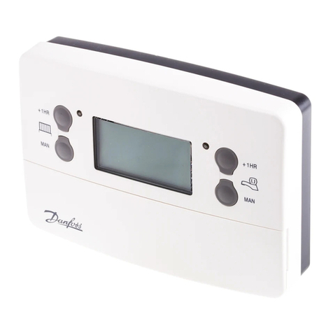
  9. Danfoss TP75-RF User manual

Danfoss TP75-RF User manual

1
Chrono-proportional Control
Traditional ON/OFF room thermostats control room temperature by switching
the circulating pump, and usually the boiler, on and off.
Because of the thermal inertia of the heating equipment and the relati ely
large switching differentiials of on/off de ices large space temperature
ariations often occur, resulting in poor comfort conditions.
Chrono-proportional Control as implemented in the TP75-RF o ercomes the
problem by ensuring that the boiler fires regularly for periods calculated to
maintain radiator temperature without o erheating and to pre ent the radiator
temperature falling to a le el which can allow down draughts from cold
surfaces, e.g. windows, to cause discomfort.
The control logic works on a proportional band of 4°F which assumes that the
boiler will operate at full load when the sensed space temperature is 4°F or
more lower than the programmed set point.
The following graph shows the relati e on/off periods per cycle against
ariances in de iation from the set point.
TP75
TP75
Control Features
The TP75-RF is a wireless communication ersion of the standard hardwired
TP75 programmable thermostat. The TP75-RF, which contains a transmitter,
works in conjunction with an RX recei er module which can be located up to
30m from the thermostat.
The TP75-RF Series of programmable room thermostats incorporate two
special features that can be enabled at the time of installation - Optimum
Start Control and Chrono-proportional Control.
Optimum Start Control (OSC)
With this enabled the e ent 1 control temperature, (which would normally be
an increase from an o ernight set-back temperature), may be programmed
to be achie ed by a desired time. The heating plant will be switched on earlier
than the programmed time by a period related to the start-up cur e selected
and the space temperature sensed at the beginning of the selected start-up
period. The diagram below indicates the switch on periods for the a ailable
start-up cur es.
If OSC is disabled then the unit will operate as a con entional room
thermostat, switching on the heating plant at the e ent 1 time with the e ent
1 temperature being achie ed in a time related to the pre ailing conditions.
Installation & Commissioning Guide
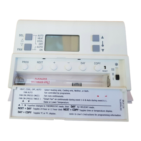
Battery Compartment Flap lowered
Specification
Control temp. range : 41°F to 85°F (5°C to 30°C)
Power Supply : 2 x AA size alkaline batteries
Transmission Frequency : 433.92 MHz
Range : 30m typical
Time Keeping Accuracy : ± 1 minute/month
Low Battery Warning : 15 days duration
Memory Retention with
Batteries Remo ed : one minute
Enclosure Rating : IP30
Maximum Ambient Temp : 113°F
Designed to British Standard : BS EN60730-2-9
O erall Dimensions Unit : Width: 136mm
Height: 88mm
Depth: 32mm
Emission Designator : 2K02D
FCC Identifier : P07 TP75RF
FCC Rules : 15°C
Programmable Room Thermostat
with Wireless Communication
TP75-RF with integral sensor
90
min
30
min
60
min
Selecting 0
effectively
disables
the OSC
function.
Desired Event 1
temperature
Degrees below the desired temperature at
the beginning of the Optimum Start Period
-3.6°F
(-2°C)
120
min
-1.8°F
(-1°C)
-5.4°F
(-3°C)
- .2°F
(-4°C) Event 1
time(0)
Available Start-up Periods
With a -3.6°F (-2°C) de iation and the 30 min. cur e selected the
heating system will switch on 15 min. before the E ent 1 time.
2
Switch No. 1- 5/2 DAY or 7 DAY.
When the switch is in the 7 DAY position each day may be programmed
with different switching times and temperatures. Placing the switch in
the 5/2 DAY position enables Monday to Friday to be programmed with
one set of switching times and temperatures, and Saturday and
Sunday to be programmed with a different set.
Switch No. 2 - OSC ON or OSC OFF
This is used to enable or disable the optimum start control (OSC)
function for e ent 1. To cater for different types of building construction
with differing fabric constants there are four start-up cur es from which
to choose, (see the diagram o er the page). These cur es dictate how
long before e ent 1 the heating equipment will be switched on. The
selectable start-up durations are 0:00, 0:30, 1:00, 1:30 or 2:00 (2
hours). (Selecting 0 effecti ely disables the function).
Once initiated the difference between the space temperature and the
e ent 1 temperature is used to generate a pre-heat period proportional
to the OSC period selected. The closer the space temperature is to the
e ent 1 temperature, the shorter the pre-heat period. Refer to the
earlier section on Optimum Start Control for more detail.
It is recommended that the initial setting of the OSC is 30 minutes. See
the section on post-commissioning.
Switch No. 3 - CHRONO or ON/OFF
With this switch set to ON/OFF the TP75 will act as a con entional room
thermostat, switching the heating plant to maintain the programmed
temperature. When set to CHRONO the control function selected by
switch No. 4 is enabled.
IMPORTANT. For systems with motorised zone al es ON/OFF mode
is recommended.
Switch No. - Chrono 6 or Chrono 3
This switch configures the TP75-RF to control different forms of
heating system, typically as follows:
Use Chrono 3 for high thermal inertia systems, e.g. floor standing cast
iron boilers.
Use Chrono 6 for low thermal inertia systems, e.g. low water content
boilers and combi. boilers.
See the earlier section on Chrono-proportional Control for more detail.
5. Position the slots in the top surface of the module over the lugs at the
top of the wallplate, and hinge downwards until the module is pressed
fully against the wallplate. Tighten the two screws from below to fix the
module to the wallplate.
6. Beforesettingtheprogrammestheunitandcircuitsshouldbechecked.
Refer to the following Commissioning Instructions.
TP75-RF Installation
The TP75-RF is supplied with a wallplate for ease of mounting. The wallplate
is used solely for fixing the electronics module to the wall and contains no
terminals.
Fixing
Fig. 2 TP75-RF or TS2 location
1. TP75-RF Selectthedesiredfixingposition.(Thisshouldadhere
to normal room thermostat practice, see Fig. 2).
Fig. 3 Wallplate fixing clearances.
2. When fixing the heating controller wallplate note that the terminals are
at the top and the vertical centre line of the heating controller is at the
right hand edge of the terminal 4 recess. Observe the clearance
required for fitting and removal, Fig. 3.
3. Fix the wallplate to the wall.
4. Before fixing the unit on to its wallplate, ensure that the four DIP
switches on the rear of the unit (see Fig. 4) have been moved to the
required settings; the choices are:-
7 day
OSC OFF
ON/OFF
Chrono 3
5/2 day
OSC ON
CHRONO
Chrono 6
Fig. 4
Factory pre-set DIP switch settings.
ABC1 2 3456
30mm min
Clearance for
screwdri er access
Wall or plaster
box mounting
holes
Aperture for
rear entry
Terminals
Knockouts for bottom
cable entry
Outline of unit
3
18. Thesemodelsaresuppliedwithafactorypre-setprogrammewhichwill
be active after a RESET has been performed. The pre-s e t
programme is shown in the chart with the Setting Instructions.
The chart also has spaces for users own times and temperaturesa s
required by them.
19. The time and programme memory are maintained by the batteries
which should last more than two years. Every 24 months the batteries
should be renewed. Internal circuitry retains the time and programme
memory for one minute, long enough for the batteries to be changed.
If the batteries olts drop, before a change is due, a battery symbol will
blink in the display. When this occurs the TP75-RF will operate
normally for 2 weeks. After the 15th midnight all relays will switch to
OFF, the unit will shut down with just the time shown. When new
batteries are fitted the unit will start to operate normally again.
Ad ise the User to enter their own times and temperatures in the chart on the
Setting Instructions.
Post-commissioning
Optimum Start Control
If this has been enabled, initially set to the recommended 30 minutes start-
up duration and the e ent 1 temperature is not achie ed by the e ent 1 time,
then refer to the Setting Instructions and increase the start-up duration one
stage, i.e. to 1 hour.
If the space temperature at the beginning of an Optimum Start sequence is
consistently lower than the programmed e ent 1 temperature by more that
2°F, then the e ent 1 temperature may not be achie ed by the e ent 1 time.
In this case the e ent 1 time should be brought forward sufficiently to
compensate, so that the comfort temperature is achie ed when actually
required.
Intelligent Anticipator
If, when the heating equipment is switched on, the room temperature is 4°F
or more lower than the programmed temperature the electronic anticipation
function measures the rate of rise in the sensed temperature and will switch
the heating plant off before the programmed temperature is reached. The
residual heat in the system after the heating plant has shut down will ensure
that the comfort temperature is achie ed. This will impro e the comfort
conditions and minimise fuel consumption.
Commissioning
12. Lower the front flap and remove the anti-discharge paper strip from
between the batteries and their contacts, and ensure the mains power
to the control circuit is switched on.
13. Press and release the recessed RESET button to ensure the factory
pre-set programme is active.
14. Once the programming has been completed, communication between
the thermostat and the recei er module has to be established.
a) SINGLE ZONE SYSTEM WITH RX1 RECEIVER
1 - Press and hold the LEARN button of the TP75-RF for at least 3
seconds. The thermostat will now transmit a continuous signal which
contains its unique identity for a period of 5 minutes.
2 - Within the 5 minute period go to the RX1 recei er module and
press both "PROG" and "CH1" buttons together and hold for at
least 3 seconds, then release.
During this process the RX1 recei er will ha e learnt the unique
transmission code of the thermostat and will in future react to all
transmissions from that thermostat.
To stop the continuous transmission on the TP75-RF unit press the
s button.
b) TWO ZONE SYSTEM WITH RX2 RECEIVER
1 - Repeat as abo e for zone one (CH1).
2 - Repeat steps one and two abo e for zone two, remembering to
press "PROG" and "CH2" on the RX2 recei er.
c) THREE ZONE SYSTEM WITH RX3 RECEIVER
1 - Repeat as abo e for zones 1 and 2 (CH1 and CH2).
2 - Repeat as abo e for zone 3, remembering to press "PROG" and "CH3"
on the RX3 recei er.
15. Establish with the customer the requirements for the operating
mode, and adjust as follows:
Clock type - 24 hour or 12 hour with AM/PM indication.
The factory pre-set is 24 hour. To convert to 12 hour, press and
hold down the NEXT and DAY buttons until the display changes,
then release. (Repeat to return to a 24 hour clock.)
Temperature display - °C or °F
The factory pre-set is °C. To convert to display all temperatures i n
°F, press and hold down the DAY and COPY buttons until the
display changes. (Repeat to return to a °C display.)
16. Check the existing space temperature by pressing and holding
downthetwobuttons:NEXTandCOPY,untilthedisplaychangesfrom
time to temperature.
17a. If the set temperature is below the space temperature, use the
buttontoraisethesettemperature.Theflamesymbolwillappearinthe
display. Check that the heating plant operates correctly.
17b. If the set temperature is above the space temperature, use the
button to lower the set temperature below the space temperature. The
flame symbol will disappear. Check that the heating plant does not
operate.
4Part No: 34065 Iss: 01 06/01
Danfoss Randall can accept no responsibilty for possible errors in catalogues, brochures and other printed material. Danfoss Randall reserves the right to alter its products without notice. This also applies to products
already on order provided that such alterations can be made without subsequent changes being necessary in specifications already agreed.
Danfoss Comfort and Building Controls
3435 Box Hill Corporate Center Dri e
Suite C
Abingdon, Maryland 21009
USA
Tel: 00 1 443 512 0266 Fax: 00 1 443 512 0270
Danfoss Mfg Co Ltd
7880 Tranmere Dri e
Mississauga
Ontario
Canada
Tel: 001 905 676 6000 Fax: 001 905 676 0279
FCC Notice: This device complies with Pt 15 of the FCC
rules. Operation is subject to the following conditions:
1) This device may not cause harmful interference
2) This device must accept any interference received
including that which may cause undesired operation.

Other Danfoss Thermostat manuals

Danfoss Icon Wireless Dial User manual

Danfoss

Danfoss Icon Wireless Dial User manual

Danfoss Link FT User manual

Danfoss

Danfoss Link FT User manual

Danfoss EFET 160 User manual

Danfoss

Danfoss EFET 160 User manual

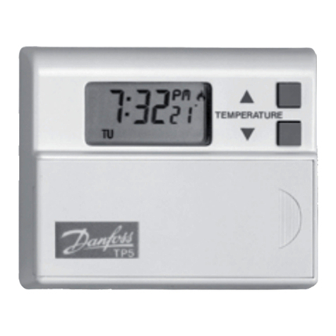
Danfoss TP5001RF User manual

Danfoss

Danfoss TP5001RF User manual

Danfoss Living Eco User manual

Danfoss

Danfoss Living Eco User manual

Danfoss TP5000 si range Guide

Danfoss

Danfoss TP5000 si range Guide

Danfoss TP5000 si range User manual

Danfoss

Danfoss TP5000 si range User manual

Danfoss LX205T User manual

Danfoss

Danfoss LX205T User manual

Danfoss DEVIreg 330 User manual

Danfoss

Danfoss DEVIreg 330 User manual

Danfoss CET B-RF Operating instructions

Danfoss

Danfoss CET B-RF Operating instructions

Danfoss FH-CWP User manual

Danfoss

Danfoss FH-CWP User manual

Danfoss RAVV-RAV8 User manual

Danfoss

Danfoss RAVV-RAV8 User manual

Danfoss TRONE-RF User manual

Danfoss

Danfoss TRONE-RF User manual

Danfoss TP9 User manual

Danfoss

Danfoss TP9 User manual

Danfoss DEVIreg 532 User manual

Danfoss

Danfoss DEVIreg 532 User manual

Danfoss TP4000 Range User manual

Danfoss

Danfoss TP4000 Range User manual

Danfoss C37 User manual

Danfoss

Danfoss C37 User manual

Danfoss ECL Comfort 310, A361 User manual

Danfoss

Danfoss ECL Comfort 310, A361 User manual

Danfoss TPONE-RF User manual

Danfoss

Danfoss TPONE-RF User manual

Danfoss CF-RP 088U0211 User manual

Danfoss

Danfoss CF-RP 088U0211 User manual

Danfoss RT 106 User manual

Danfoss

Danfoss RT 106 User manual

Danfoss LX 420 User manual

Danfoss

Danfoss LX 420 User manual

Danfoss RET 230LS User manual

Danfoss

Danfoss RET 230LS User manual

Danfoss 100064 User manual

Danfoss

Danfoss 100064 User manual

Popular Thermostat manuals by other brands

Oras Stabila installation guide

Oras

Oras Stabila installation guide

Caleffi solar iSolar DL3 manual

Caleffi solar

Caleffi solar iSolar DL3 manual

Hunter 40135 manual

Hunter

Hunter 40135 manual

Honeywell T7351 Information

Honeywell

Honeywell T7351 Information

TOTALINE SIGNATURE CPV230 owner's manual

TOTALINE

TOTALINE SIGNATURE CPV230 owner's manual

Honeywell CT87 Installation quick guide

Honeywell

Honeywell CT87 Installation quick guide

Pro1 Technologies T601-2 Operation manual

Pro1 Technologies

Pro1 Technologies T601-2 Operation manual

Smart temp ISIS user manual

Smart temp

Smart temp ISIS user manual

Watts Tekmar WiFi Thermostat 561 user manual

Watts

Watts Tekmar WiFi Thermostat 561 user manual

OJ Electronics ETN4-1999 instructions

OJ Electronics

OJ Electronics ETN4-1999 instructions

Honeywell T641A installation instructions

Honeywell

Honeywell T641A installation instructions

La Crosse Technology WT-137U instruction manual

La Crosse Technology

La Crosse Technology WT-137U instruction manual

Carrier Debonair 33CS250-01 owner's manual

Carrier

Carrier Debonair 33CS250-01 owner's manual

Mi-Heat SAS816RF instruction manual

Mi-Heat

Mi-Heat SAS816RF instruction manual

Honeywell Lyric installation guide

Honeywell

Honeywell Lyric installation guide

Honeywell Home RC7189WS1000 quick start guide

Honeywell Home

Honeywell Home RC7189WS1000 quick start guide

Coati 12617 operating instructions

Coati

Coati 12617 operating instructions

American Standard ASYSTAT605 Installer's guide

American Standard

American Standard ASYSTAT605 Installer's guide

manuals.online logo
manuals.online logoBrands
  • About & Mission
  • Contact us
  • Privacy Policy
  • Terms and Conditions

Copyright 2025 Manuals.Online. All Rights Reserved.