Danmeter CSM 2 User manual

Cerebral State Monitor
Model CSM 2
User Manual
Rx only
Danmeter A/S
Kildemosevej 13, DK-5000 Odense C, Denmark
Tel.: +45 63 11 29 30
Fax: +45 63 11 29 31
www.danmeter.com


Table of Contents
1About this Manual .............................................................................................................................1
1.1 Device description ..................................................................................................................1
1.2 Indications for Use..................................................................................................................1
1.3 List of Symbols .......................................................................................................................2
2Installation and Preparation..............................................................................................................2
3Skin Preparation and Sensor Positioning..........................................................................................3
4Description of the Device ..................................................................................................................4
4.1 General Overview....................................................................................................................4
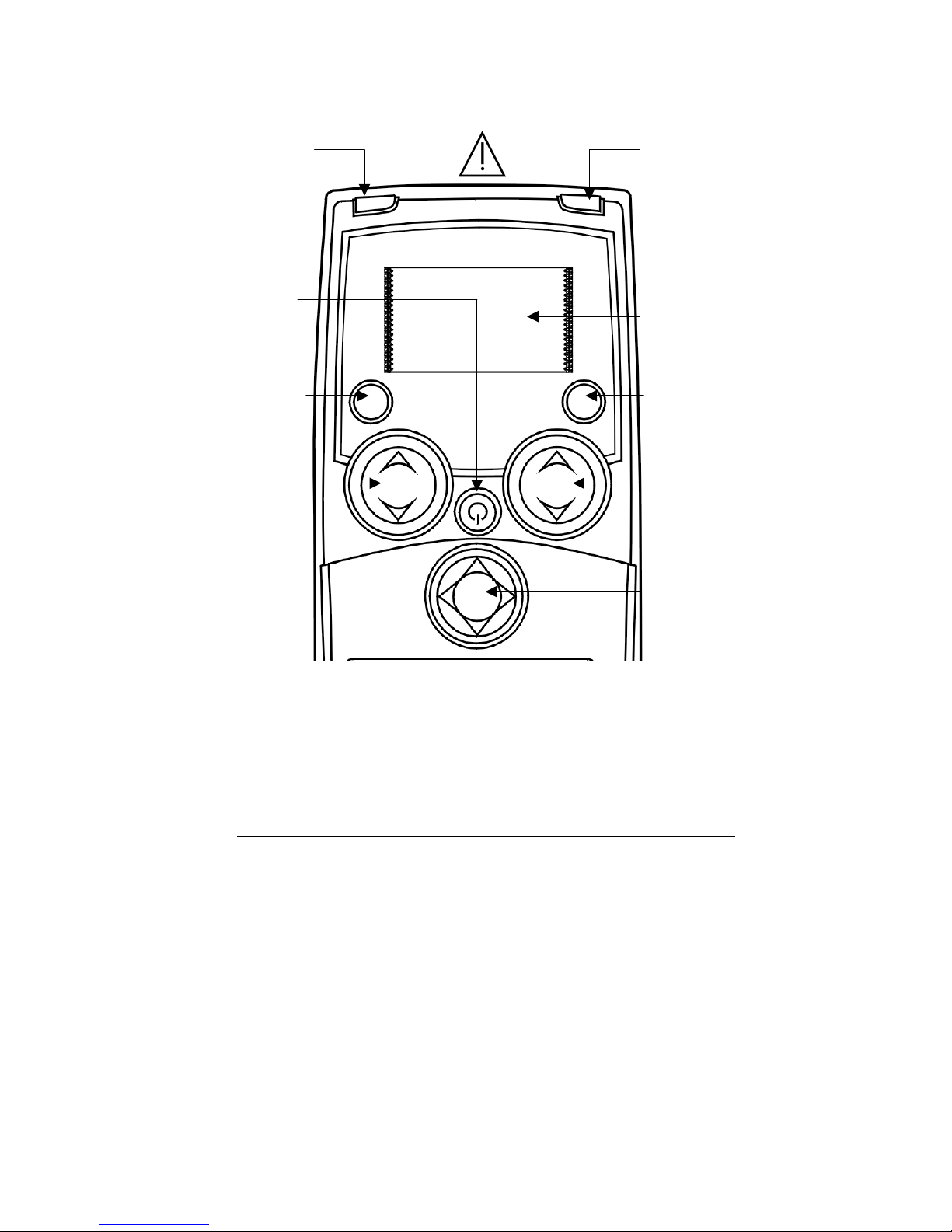
4.2 Keys and Controls Overview....................................................................................................5
4.3 Light Indicators.......................................................................................................................6
4.4 Description of Keys.................................................................................................................6
4.5 Operation Display Modes........................................................................................................7
4.6 Setup Menu.............................................................................................................................9
4.7 Settings.................................................................................................................................10
4.8 Events...................................................................................................................................11
4.9 CSM Parameters ...................................................................................................................12
5Principle of Operation .....................................................................................................................14
5.1 High Quality Amplifier............................................................................................................14
5.2 Measurement Principle .........................................................................................................14
5.3 CSI Scale...............................................................................................................................15
5.4 EMG ......................................................................................................................................16
5.5 Burst Suppression Indicator .................................................................................................16
5.6 Artifact and Noise Control.....................................................................................................16
6CSM Battery / CSM Power Operation...............................................................................................17
6.1 Using CSM Power and CSM Rechargeable Batteries.............................................................17
7Data Recording via CSM Link...........................................................................................................18
7Data Recording via CSM Link...........................................................................................................19
7.1 CSM Link Software ................................................................................................................19
7.2 CSM Link ...............................................................................................................................19
8Specifications ..................................................................................................................................21
9Accessories.....................................................................................................................................22
10 Maintenance....................................................................................................................................22
11 Troubleshooting..............................................................................................................................24
12 System and Error Messages ...........................................................................................................26
13 Safety and Warranty........................................................................................................................26
14 Service and Contacts.......................................................................................................................28
15 Technical description.......................................................................................................................30

This manual is published by Danmeter A/S, who reserves the right to improve and modify the
contents without prior notice. Modifications will, however, be published in future editions. All rights
reserved.
Cerebral State Monitor, CSM & CSI are trademarks of Danmeter A/S
Products manufactured by Danmeter A/S, Kildemosevej 13, DK-5000 Odense C, Denmark
US-English
PN 561105003-04
Declaration of Conformity:
Danmeter A/S hereby declares that the Cerebral State Monitor complies with the following
standards:
EN (IEC) 60601-1,
EN (IEC) 60601-1-2,
EN (IEC) 60601-2-26
UL 60601-1:2003
CAN/CSA-C22.2 No. 601.1-M90
CAN/CSA-C22.2 No. 601.1S1-94
CSA 601.1 Amendment 2:1998
CAN/CSA 601-2-26

Cerebral State Monitor - CSM DFU Page 1
1 About this Manual
This manual is intended to assist the user in operating the Cerebral State Monitor (CSM) in a safe
and effective manner.
This version of the manual was originally drafted, approved and supplied by Danmeter A/S in English.
WARNINGS are directions which, if not followed, could cause fatal or serious injury to an
operator, patient or any other person.
CAUTIONS are directions which, if not followed, could cause damage to the equipment
described in this manual and/or any other equipment or goods, and/or cause
environmental pollution.
NOTES are intended to highlight unusual points as an aid to the operator.
1.1 Device description
The Cerebral State Monitor (CSM) is a non-invasive measurement tool for use by trained healthcare
professionals to measure the level of consciousness (LOC) in all areas of the hospital. Based on
EEG, an index (CSI) is calculated, which is used in the estimation of LOC. The CSM displays the CSI
but does not perform any data interpretation (i.e., all data interpretation is performed by a
physician).
1.2 Indications for Use
The monitor is intended for use in monitoring the hypnotic state of the brain by data acquisition of
EEG signals of the anesthetized or sedated patient in all areas of the hospital.
Before operating the monitor read this manual thoroughly, with particular attention to all
warnings and cautions.
Note:
Although the monitor is built and tested to exacting specifications, it is not intended to
replace the supervision of level of consciousness monitoring by medical personnel. The user
should become thoroughly familiar with the features, operations, and accessories of the
monitor and exercise vigilance in its utilization.
Caution:
Federal law (U.S.A.) restricts this device to sale, distribution, and use by or on the order of a
p
hysician.

Cerebral State Monitor - CSM DFU Page 2
1.3 List of Symbols
Type BF equipment
On / Off
Attention, consult accompanying documents
Do not dispose of in refuse collection. Dispose of at a recycling
station or equivalent in accordance with directive 2002-96-EC WEEE.
2 Installation and Preparation
The Cerebral State Monitor system CSM007 includes the following:
Cerebral State Monitor CSM Wireless Link
Patient Cable CSM Software CD
Rechargeable 9V Battery User manual (this document)
Power Adapter (2 pieces) Power Cable (2 pieces)
RS-232 Cable/USB Cable Carrying case
Velcro strip 1.7x0.9” Clip for patient cable
For replacement accessories, refer to chapter 9
Note
The performance of the CSM monitor by EEG acquisition, processing and calculation of the
CSM parameters and waveforms in the CSM monitor are ONLY guaranteed by the
manufacture when using the CSM Procedure Pack, part no. DMX005.
The possibility to use standard ECG electrodes is NOT RECOMMENDED

Cerebral State Monitor - CSM DFU Page 3
3 Skin Preparation and Sensor Positioning
To ensure low sensor impedance, clean skin with mild soap and water is recommended as a skin
cleanser.
The CSM Procedure Pack contains a skin preparation product and 3 neuro sensors.
Dry-abrade the skin gently using the skin prep product or with a dry wash cloth or gauze, to remove
the non-conductive skin layer. See diagram below.
Position of the three sensors from your CSM Procedure Pack according the diagram below
Shown above is a left sided setup; right sided is also acceptable. Place sensors at the side farthest
from the surgical area.
The advanced signal processing of the monitor ensures that a deviation in the positioning of the
sensors up to 2 cm (0.78 in) has no significant influence on the index. However, it is recommended
to place the sensors on an area of the skull where only a few muscle fibers are present in order to
achieve the best quality signal.
Middle of forehead
Left side of forehead
Mastoid left side
Note: Alcohol is not recommended as a skin cleanser; it leaves a film layer that may cause
high sensor impedance. If alcohol is used, ensure 30 second dry time.
Caution:
-
Make sure no part of the sensors is in contact with any other conductive parts including
earth/ground.
-
If skin rash or other unusual symptoms develop, remove sensors from patient.
-
Change sensors every 24 hours to check skin integrity.
Note: Once the sensors have been secured on the skin, attach the color-coded wires on the
patient cable to appropriate sensor.
Note: The performance of the CSM is only guaranteed by the manufacturer when the CSM
Procedure Pack is used.

Cerebral State Monitor - CSM DFU Page 4
4 Description of the Device
4.1 General Overview
Battery lid Battery
compartment
Patient cable
connection
CSM
power/charge
connection
On/Off
-
+

Cerebral State Monitor - CSM DFU Page 5
4.2 Keys and Controls Overview
2
RED Error
light
Error
Charge
Mute
Set
Display
Event
3
GREEN Power
adapter
5
Mute
key
7
Display
key
1
On/Off 4
Display
area
6
Set Event
key
8
Event Type
key
9
Control
key

Cerebral State Monitor - CSM DFU Page 6
4.3 Light Indicators
2RED Error light
Lights up when neuro sensor error situations are detected
3 Lights when power adapter is connected
4.4 Description of Keys
1 Power On
Press once
1 Power Off
Press and hold until “Power Off” bar disappears
1 Wireless Link connection, disconnection or reconnection
Press twice within 1 second
5 Mute key Mutes alarms
6 Set Event key / Set link
7 Display key
Changes between graphical and information screen
7a - For immediate impedance update. Press down firmly for one second
8 Event key
Select event type / Select link (accessory)
9 Control key
Used for menu selection of parameter settings
9a - Use the Control key to scroll in the menus or set values
9b - Select a submenu or function
9c - Go back one menu level

Cerebral State Monitor - CSM DFU Page 7
4.5 Operation Display Modes
The CSM always starts with display A
Switch between display A, B, C, D and E by pressing the Display key (7).
Display Mode D
CSI trend histogram with 5-minute interval showing average, lowest and highest
CSI values within the interval. EMG% is displayed as a bar in the right panel
Display Mode C
CSI trend curve with event markers and BS curve. EMG% is displayed as a bar in
the right panel. Operation time and numeric value of the actual CSI and BS%. The
time scale for the trend curve is 5.27 minutes and each tag is 60 seconds
Display Mode B
Displays 3 seconds of EEG waveform. Use Event key (8) to scale up and down. EEG
scales are ±200μV, ±100μV (default), ±50μV, ±20μV and ±10μV
Display Mode A
Main information window with CSI, BS%, EMG%, SQI%, clock, operation time and
battery operation.
Display Mode E.
Sensor impedance, CSI, BS%, clock and operation time. When display E is active,
the sensor impedance is updated every 60 seconds. Press Display key (7a) firmly
for immediate impedance update
10:12:05
0:47:11
10:12:05
0:47:11

Cerebral State Monitor - CSM DFU Page 8
The EEG waveform derives from the signal recorded between the frontal and mastoid electrodes. The
frequency content is 2-35 Hz. If the EEG amplitude is low then in some conditions the ECG might be
detectable in the EEG waveform
EMG% is shown in the display as a bar in the right-hand side. Operating time and numerical value for
current CSI and BS%. The time scale for the histogram graph is 180 min. The interval between each
tag is 60 min. The high-low bar in the current time interval (high-low bar to the far right) is updated
dynamically.
Special display features
Artifact Sensor
alarm
CSI - - -?-
BS% - - -?-
EMG - - -?-
SQI SQI value -?-

Cerebral State Monitor - CSM DFU Page 9
4.6 Setup Menu
General menu structure and menu selections
Top Menu
BS% 0 47 CSI
Menu 1
Alarm
Config
Device information
How to select menu settings from Display Mode
1. Remove battery lid.
2. From any Display Mode, press any arrow on the Control key (9).
3. The top menu appears.
4.
Note:
The last menu used is chosen.
How to set parameter values
1. Press the Control key (9a) to select menu.
2. Press the Control key (9b) to enter submenu.
3. Press the Control key (9a) to select parameter.
4. Press the Control key (9b) to highlight parameter value.
5. Press the Control key (9a) to select parameter value.
6. Press the Control key (9b) to accept setting or (9c) to cancel the selection and return
without any change.
7. Press the Control key (9c) to go back in one menu level steps.
If the Control key has not been activated in 20 sec. the CSM returns to Operation Display Mode and
stores the settings.
Note:
The change of settings will only be stored for future use after returning to Operation
Display Modes.

Cerebral State Monitor - CSM DFU Page 10
4.7 Settings
Parameter Menu Description Values (Default)
High Alarm Alarm Selects the CSI Alarm High Option ON/OFF (OFF)
Low Alarm Alarm Selects the CSI Alarm Low Option ON/OFF (OFF)
High Limit Alarm Selects the CSI High Alarm Level 2-99
(60)
Low Limit Alarm Selects the CSI Low Alarm Level 1-98
(40)
Language Config Selects device language English
Contrast Config Selects display contrast 15-35
(20)
RF interface Config Select radio link active. If turned
OFF the link is completely inactive.
ON/OFF (ON)
Set clock Config Sets clock: Date Format, Year,
Month, Date, Hours, Minutes,
Seconds
Back light Config Sets display light and light
brightness
0 = Off
1 = Normal (1)
2 = Bright
AutoLNK Config Automatically establishes a
wireless link to any CSM link within
approx. 10 feet or to a specified
CSM link.
Inactive/Active/SN
(Inactive) SN is
only displayed if
link is established
The AutoLNK function
When AutoLNK is set to Inactive:
- active CSM Link(s) within range will pop-up in the Link display. Select the CSM Link serial
number you would like to connect to.
When AutoLNK is set to Active:
- active CSM Link within range will automatically be connected to CSM monitor
When AutoLNK is set to SN:
- CSM monitor automatically connects to the dedicated CSM Link if within range.

Cerebral State Monitor - CSM DFU Page 11
Device Information:
Select submenu.
BS% 0 47 CSI
Device information 1
Info
Link
Log
Info:
• Serial number.
• SW version.
• CSI version.
• AD version.
Link:
• - indicates no CSM Link connected.
• If CSM Link connected the CSM Link serial number and software version will be shown.
Log:
• Serial number.
• #1 total no. of CSM sessions.
• #2 total no. running hours.
4.8 Events
Pressing the Set Event key (6) results in a continuously numbered event with no description
displayed.
Pressing the Event Type key brings up the following selection menu:
BS% 0 47 CSI
Event types 1
Induction
Intubation
Maintenance
The following options event descriptions can be selected: Induction, Intubation, Maintenance,
Surgery, Injection, Note, End Maintenance and Movement.
When the desired option has been selected, press the Set Event key (6) to confirm. If no selection is
made within 5 seconds the system returns to the current Display Mode. Only the event numbers are
visible on Display Mode C. Event names will only be displayed when using the CSM Link option.
Events can be set with intervals of 3 seconds.

Cerebral State Monitor - CSM DFU Page 12
4.9 CSM Parameters
BS% Indicator
The amount of Burst Suppression (very low-amplitude or “flat” EEG) is displayed in all Display Modes
at the top left hand side. Please refer to Section 5.5 for further information on the BS%
measurement.
EMG% and EMG bar
The EMG level is displayed either as a numerical percentage (0-100%) value in Display Mode A or
graphically as a bar at the right hand side in Display Mode B. Please refer to Section 5.4 for further
information on the EMG measurement.
Signal Quality Indicator (SQI%)
SQI% measures the quality of the acquired EEG signal. The calculation is based on the number of
artifacts during the last minute. The electrode-to-skin impedance is included in the SQI% calculation.
Higher electrode-to-skin impedances reduces the SQI%. Only electrode-to-skin impedances at 1 and
1 kΩwill result in a SQI% at 100. This quantity is displayed numerically as a percentage (0-100%,
100% equals best signal quality) in Display Mode A.
If the impedance of the white or black sensors exceeds 1kΩ, the SQI will fall gradually. Poor
impedance conditions may cause the SQI to fall to 50%.
Sensor Impedance
The impedance of the white and black sensors is continuously measured and displayed in Display
Mode E. Low sensor impedance values (typically between 1 and 3 kΩ) are essential for good
monitor operation. A “<1kΩ” readout means that sensor impedance is optimal.
Sensor Alarm
The Sensor Alarm signals the interruption of reliable CSI calculation due to corrupted or interrupted
EEG. This is usually caused by the use of diathermia or a faulty sensor connection (high sensor
impedance or disconnection of sensor leads). Should any of these situations occur, the Red Error
light (2) will turn on. The CSI is not calculated during these periods, but is replaced by -?-.
Alarms (High / Low)
Alarms can be set to signal the moment when the CSI rises above and/or falls below preset limits.
The High and Low Alarms can be turned on or off from the Alarm Menu, where the High and Low
Alarm limits can also be set. The High Alarm is ONLY activated when the current CSI has been lower
than the High Alarm value. This is convenient when the High Alarm is set in the awake patient. If High
Alarm is set to 60 and High Alarm ON, then the CSI must be lower than 60 once before the High
Alarm is activated. If the current CSI goes higher than 60 the CSM monitor alarm sounds.
Same functionality is present for Alarm Low.

Cerebral State Monitor - CSM DFU Page 13
Battery Symbol
An icon labelled “BAT” in Display Mode A indicates the remaining battery capacity. For further
information on battery operation of the CSM, please see section 6.
Battery about 50-percent charged
Battery charging when icon animates
Battery fully charged (if not animated)
LINK Signal Symbol
An icon labelled “LNK” in Display Mode E indicates the state of the data transfer connection via the
CSM Link. For further information on the CSM Link feature, please see section 7.
Acoustic signals
Start-up 3 beeps
Event 1 beep
Alarm (High/Low) 2 beeps per sec. (Mute = mute 60 sec.)
Low Battery 2 beeps per sec. (Mute = mute 60 sec.)
Note:
ONLY CSM Battery (CSMX04) will be charged in CSM Monitor

Cerebral State Monitor - CSM DFU Page 14
5 Principle of Operation
5.1 High Quality Amplifier
An instrumentation amplifier collects ongoing EEG with a high Common Mode Rejection Ratio
ensuring a high-quality EEG acquisition. Special artifact detection algorithms are used to eliminate
their effects on subsequent CSI calculations.
5.2 Measurement Principle
The performance of the CSM is based on the analysis of the frequency content of the EEG signal.
The energy of the EEG is evaluated in specific frequency bands. These are used to define two energy
ratios called alpha (α) and beta (β). Both of these show a shift in energy content from the higher to
the lower frequencies during anesthesia. The relationship between these quantities is also analysed
as a separate parameter (β-α).
Hz
Hz
ratio E
E
126
5.4230
ln
−
−
=
α
Hz
Hz
ratio E
E
2111
5.4230
ln
−
−
=
β
The monitor also on-line evaluates the amount of instantaneous burst suppression (BS) in each
thirty-second period of the EEG. This measurement quantifies the amount of “silent” or “flat” EEG
periods characteristic of the deepest levels of hypnosis.
These four parameters are used as input to a fuzzy logic classifier system that calculates the
Cerebral State Index.
FUZZY LOGIC
CLASSIFIER CSI
βratio
BS%
αratio
β-α
EEG

Cerebral State Monitor - CSM DFU Page 15
5.3 CSI Scale
The CSI is a unit-less scale from 0 to 100, where 0 indicates a flat EEG and 100 indicates EEG
activity corresponding to the awake state. The range of adequate anesthesia is designed to be
between 40 and 60. All values in the table are approximate values based on the mean values of the
patient behaviour.
The relationship among the CSI, the clinical state and the OAAS1score is shown in the table below
CSI Clinical State OAAS
90 – 100 Awake 5
80 – 90 Drowsy 4
60 – 80 Light anesthesia or sedation 3
40 – 60 Range considered as adequate for
surgical anesthesia
2-1
10 – 40 Deep anesthesia, in most cases
accompanied by burst suppression
1
0 – 10
Close to coma, BS (burst suppression)
larger than 75. When CSI is below 3,
the EEG is practically iso-electric.
<1
The prediction probability (Pk) between the CSI and the OAAS was 0.92
The OAAS score correspond to:
OAAS
Clinical State
5 Responds readily to name spoken in normal tone
4 Lethargic response to name spoken in normal tone
3 Responds only after name called loudly and/or repeatedly
2 Does not respond to mild prodding or shaking
1 Does not respond to noxious stimulus
1Observers Assessment of Alertness and Sedation

Cerebral State Monitor - CSM DFU Page 16
5.4 EMG
High levels of facial muscular or electromyographic (EMG) activity can interfere with the CSI under
certain circumstances. The monitor incorporates an EMG filter that removes most of the potential
interfering EMG activity. The EMG bar shows the energy of the EMG level in the 75–85 Hz frequency
band (0–100 logarithmic). The bar is located on the right side of the display.
EMG activity is expected to be present when the patient is awake. When the patient is asleep, EMG
activity can increase due to:
• Reflex reactions to painful stimuli during surgery.
• Lack of muscular relaxation.
• Muscular rigidity caused by some opioids (analgesics).
• Presence of large external electrical fields, e.g. diathermy.
The EMG bar should be checked frequently, especially in case of a sudden increase in the CSI. If the
increase in CSI is accompanied by an increase in muscular activity, there is a risk that EMG is causing
interference. When this happens, attention must be paid to the stimuli received by the patient during
surgery. In the presence of hypnotically unrelated EMG, administration of a neuromuscular blocking
agent will cause the CSI to decrease. Since patients receiving neuromuscular blocking agents cannot
exhibit movement as a sign of arousal, the CSI is a valuable tool in their anesthetic management.
5.5 Burst Suppression Indicator
The monitor includes a Burst Suppression indicator to show periods when the EEG is iso-electric or
“flat”. The indication appears in the upper left-hand side of the graph window in the display and
shows the percentage of burst suppression over the last 30 seconds of the EEG signal. A BS% = 20
readouts means that the EEG has been iso-electric during 20% of the last 30 seconds.
5.6 Artifact and Noise Control
The artifact rejection algorithm ensures that the incoming EEG is not contaminated with noise. When
excessive noise is detected, the signal quality index is reduced reflecting the disturbance. The
artifact rejection algorithm will be active especially when diathermy and equipment creating external
interference is used.
Table of contents
Other Danmeter Medical Equipment manuals