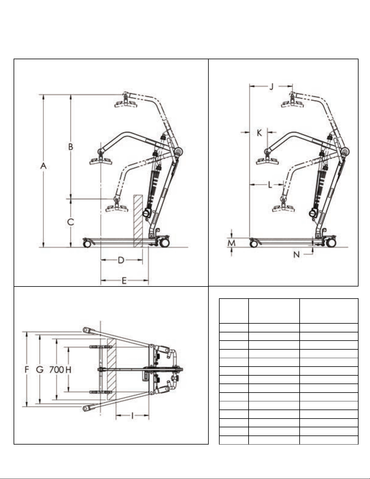
Dansons Group DM-PL350 User manual

FULL BOD Y P A TIEN T L IFT
Model:DM-PL 0/DM-P L 0 H
Ensure the product has been assembled according to the instructions in
this manual. All operators should read and understand the instructions for
safe and proper operation of the patient lift.
*DM-PL350 MODEL SHOWN
Dansons
Medical

This page was intentionally left blank.

DM-PL350
MAX LOAD: 350LB
S/N: DM-PL350YYMM1XXX
MASS OF LIFT:77LB(35KG)
678-735-4488

i
i
Product Description
Intended Use
The L 0
provides added comfort for the patient
.
intend patients who are completely immobile or
totally dependent on th lift for transfers. intended to be used
for transfers of the patient in and out of bed, wheelchair, to
and from commode, or any other type of surface.


Safety Instructions

WARNING!
•
•
•
•
•
•
•
.
•
•
•
•
•
•.
•
•
•
i

6
FEATURES & OVERVIEW
i
Easy Tools Screwdriver
30.40 lb 8.20 lb
(13.8 kg) (3.7 kg)
0.70 lb
(0.3 kg)
7.20 lb 11.00 lb
(3.3 kg) (5.0 kg)
8.60 lb 15.20 lb 0.60 lb
(3.9 kg) (6.9 kg) (0.3 kg)
4.20 lb 5.60 lb
(1.9 kg) (2.5 kg)
Emergency lowering11
Handle
8
Hand Control
Charger
Control Box
10 Spreader Bar
13
**Base
12
Actuator
(P 0 ONLY)
Leg Opening Pedal7
6
5
Rear Caster
Hydraulic Pump
(PL160H ONLY)
9Mast
1
Front Caster
Boom
4
3
2
** Heaviest detachable part
• Prior to assembly, unpack and inspect all parts from the shipping carton.
• Easy tools are provided to assist with initial set up. To ensure maximum
safety, product should not be put into use until all connections are tightened
using standard tools.
*DM-PL350 MODEL SHOWN
Contact us immediately if any parts are damaged or missing.

7
mm (in) mm (in)
A1753.8 (69.0) 1756.3 (69.1)
B1198.5 (47.2) 985.5 (38.8)
C555.3 (21.9) 770.8 (30.3)
D479.4 (18.9) 515.2 (20.3)
E547.2 (21.5) 547.2 (21.5)
F860.3 (33.9) 860.3 (33.9)
G792.5 (31.2) 792.5 (31.2)
H513.9 (20.2) 513.9 (20.2)
I376.9 (14.8) 376.9 (14.8)
J514.7 (20.3) 517.1 (20.4)
K227.0 (8.9) 227.0 (8.9)
L411.2 (16.2) 289.2 (11.4)
M106.2 (4.2) 106.2 (4.2)
N19.4 (0.8) 19.4 (0.8)
DM-PL350 DM-PL350H

8
1 4-Points Spreader Bar
2 4" Rear Plastic Caster with Brake
3 3" Dual Front Plastic Caster
4 Power Control Unit
5 Detachable Handle
1 2 pt. Spreader Bar
2 6 pt. Spreader Bar
3 Upgrade Kit to Power Control system
(For PL350HONLY)
Specifications of Control Unit
Input Voltage
220-240VAC 50Hz / 110-120VAC 60Hz
Output Voltage
24 VDC
Battery Pack
24 VDC 2.9AH
Lift Control
Handset and Panel
Protection Class
IP54 (Protection against dust and splash of water)
Sound Level Under Full Load
16db
Sound Level Under No Load
11db
Cycles Per Charge
15 full cycles under full load
Over-Duty Warning
by LCD
Battery Status
by LCD
Duty Cycle
10% Duty cycle (Max 2 minute ON, 18 minute OFF)
Dimensions & Specifications
DM-PL350H
DM-PL350

9
Installation
Step 1: Remove the base out of the box, and locate the following
1
2
3
2
X 1
2
2
1
Step 3:
Step 2:
X 1
X

10
Step 4: the plastic cover and plastic washer to the boom at the mounting hole hen
insert the boom to the mast, and secure it using
Step 5a (FOR PL350 ONLY)
WARNING!!! There are two mounting holes on the mast bracket, make sure to mount the
actuator to the LOWER HOLE.
1
1
2
3
3
It is critical to have
the motor part of the
actuator to face the
same direction as the
big arrow as follows.

Step 5b: (FOR PL350H ONLY) Secure the
lower end of the hydraulic pump to the mast
bracket using a pin and retaining ring as
shown, and
WARNING!!! There are two mounting
holes on the mast bracket, make sure to
mount the hydraulic pump to the UPPER
HOLE.
Step 6: Insert the plastic cover to the spreader bar stem, and align the two side holes on the
plastic cover with the holes on the spreader bar stem. Then insert the black plastic
into each hole.
Step 7: Secure the spreader bar to the boom using a pin and retaining ring as .
1
1
2
2
2
2
1

Step 1
1

Operating Instructions
i
Double check all assemblies for tightness and read operating
instructions carefully prior to use.
For optimum performance the lift should be transported and stored in
following condition range:
•
•
•
For optimum performance the lift should be operated in following condition
range:
•
•
water vapor partial pressure greater than 5 kPa
• 70 kPa to 106 kPa atmospheric pressure
The lift will not have any potential electromagnetic or other interference with
other devices.
PREPARATION BEFORE LIFTING
•
• Verify the Lifting and Lowering Functions by pressing either the UP or DOWN
button on the hand control once.
• Position the base of the lift around or under the object.
• Widen the base and disengage the caster brakes.
Do not attempt to transfer a patient without prior approval of the person’s nurse.
Also, do not transfer without having studied the instructions and performed
several practices in operating the product. Together (with the patients doctor,
nurse, or medical attendant) select a sling that is both practical and comfortable.
The sling selected should be one that serves the needs of the patient, while
providing the patient with optimal safety. Never interfere with the lift, unless
instructed by the attendant. Have a doctor, nurse, or medical attendant
is used to transfer a new user.
i
1

To raise the boom:
-Turn the release knob
clockwise until it stops.
-Use the handle bar to
pump the piston
To lower the boom:
The release knob controls
the speed of the piston as
it’s lowering. This may cause
serious injuries if the piston is
lowered too fast.
-Slowly turn the
release knob
counter-clockwise, stop
once the boom is slowly
lowering
-Turn the release
knob clockwise to stop
the lowering.
Pump
Handle
Bar
Piston
Pump Serial
Number
Release
Knob
X
X
X
X
Patient Lift Hydraulic Pump Unit Operating Instruction

Control Box Overview
WARNING!
Actuator
Not Used
Hand Control
Emergency Stop Button
Cable Organizer
Charger
AC In
Down Button
Battery Indicator

Battery Indicator Display Signs
Battery Indicator Signs - Charging
Charging: AC Charging Cord
Pressed inRelease

17
LED Indicator
* Green = In Use
* Blank = Standby
Lifting
Lowering
Operating Lift: Using Hand Control
Operating Lift: Using Control Box
Lowering
The red button must be in released position to operate lift.
situation.

Warning! - Overloaded
Warning! - Low Battery
Warning! - Connection
This manual suits for next models
1
Table of contents
Popular Medical Equipment manuals by other brands

HomeFree
HomeFree FDU-830 Operational instructions

Chattanooga
Chattanooga Intelect RPW 2 user manual

Hoyer
Hoyer Ascend User instruction manual & warranty

Sunrise Medical
Sunrise Medical Jay Fit Cushion User instruction manual & warranty

ProMed
ProMed Tens 1000 s Instruction leaflet

Otto Bock
Otto Bock 3R93 Instructions for use

Arjo
Arjo Typhoon Instructions for use

Boston Scientific
Boston Scientific Vercise DB-5572-1A Directions for use

Welby
Welby 78-50D4 instruction manual

Winco
Winco TransMotion TMM4 PLUS-154 Operation manual

Future Mobility Healthcare
Future Mobility Healthcare PRISM Supreme Installation and operating instructions

BTT
BTT Melmak Instructions for use