Dantel 44202 User manual

CAUTION
Install or remove modules from the shelf only when the power is off.
If you install a module in the shelf with the power on, the internal
circuitry may suffer damage and the product warranty will be void.
Remove and install circuit boards only in a static-safe environment
(use antistatic wrist straps, smocks, footwear, etc.).
Keep circuit boards in their antistatic bags when they are not in use.
Do not ship or store circuit boards near strong electrostatic, electromag-
netic, magnetic, or radioactive fields.
For more complete information on electrostatic discharge safety
precautions, refer to BellcoreTM Technical Reference #TR-NWT-000870.
Copyright 1998 by Dantel, Inc. • Dantel is a registered trademark of Dantel, Inc. • ISO 9001 Registered
Printed in the U.S.A.
INSTALLATION&OPERATION MANUAL
44202-0898<90-00004>
44202
202 COMPATIBLE
MODEM
About this Practice:
This practice has been reissued to:
• Replace modem alignment
procedure and Table C, in
Installa-
tion
section, with new procedure.
Issue date: August 1998
Reissued Practices: Updated
and new content can be identified
by a banner in the right margin.
UPDATED
Table of Contents
Ordering Information ............................................................................ 2
General Description ............................................................................... 2
Circuit Description ................................................................................ 2
Application Information ......................................................................... 5
Installation ............................................................................................ 6
Operation ............................................................................................. 12
Technical Specifications ....................................................................... 14
Warranty ............................................................................................. 16
44202-00
202 MODEM
A11-44202-00 REV__
ON
TEST
MON
XMT
4W
2W
LINE
MON
LINE
ON
ABL
ON
DLB
TD RD
RTS CD
DTR CTS
XMT
LEVEL
RCV
GND
RCV

PAGE 2 44202-0898<90-00004>
ORDERING INFORMATION
NOTE: This section lists the different options available for this product. To order any of the available
options, contact Dantel Inside Sales through our toll-free number, 1-800-432-6835.
OPTION NUMBER FEATURES
A11-44202-00 202 Compatible Modem
GENERAL DESCRIPTION
T
his practice describes the Dantel 44202 202 Compatible
Modem and supports installation and maintenance to the
change-out level.
This module provides Bell type 202 (4-wire) or 103 (2- or 4-wire)
data communications between distant digital equipment locations.
It also provides on-board loop-back testing and multiple data
interface inputs.
The 44202 is a plug-in P.C. board module that fits into any
400-type or similiar equipment housing. The front panel has:
♦Jacks.
♦LEDs.
♦Switches.
♦Test points.
♦Level setting potentiometers.
The are no options for the 44202 and it is not equipped to accept
subassemblies.
CIRCUIT DESCRIPTION
The 44202s functional schematic is shown is Fig. 1. The circuit
consists of:
♦Multiple data interfaces.
♦Modem IC.
♦Transformers.
♦Adjustable transmit and receive amplifiers.
♦Regulated power supply.

44202-0898<90-00004> PAGE 3
FIG.1 - FUNCTIONAL SCHEMATIC, 44202 MODEM
CIRCUIT DESCRIPTION
31
32
30
29
28
27
26
25
5
6
7
8
12
11
10
9
3
4
2
1
DTR
RTS
TD
RD
CD
CTS
DSR
SIGNAL
GROUND
TX+
TX-
RTS+
RTS-
RTS+
RX-
CD+
CD-
TX+
TX-
RX+
RX-
TTL/
CMOS
RS-422
RS-485
XMT
GAIN
LO HI
1
2
3
4
5
TRANSMIT
AMP
51
40
39
41
42
49
35
17
RECEIVE
AMP
RCV
GAIN
2W
S1-C
4W
2W
S1-A
4W S1-B
2W
4W
21
20
19
16
15
14
13
TD
RTS
DTR
CTS
CD
RD
DSR
RS-232
45
47
DLB
ALB
TTL
I/O GATING
& DRIVERS
RTS
DLB
ALB
S4
S3
S2
NO TEST TEST
T
TO
O
TO
I/O GATING
& DRIVERS
I/O GATING
& DRIVERS
I/O GATING
& DRIVERS
DTR
RTS
CD
CTS
RD
TD
MODEM
IC
+5 VDC
I/O
LOGIC
18
19
21
22
17
+5 VDC
S5
MODEM
CONFIGURATION
SELECT
XTAL
XMT
LEVEL
+5 VDC MASTER
SLAVE
XMT
-
+
-
+
RCV
LEVEL
MASTER
SLAVE
RCV
REGULATED
POWER
SUPPLY
-5 VDC SOURCE
+5 VDC SOURCE
-12 VDC SOURCE
+12 VDC SOURCE
NOTES:
1. Only one interface can be active at a time. Having two data interfaces active will caue sporadic operation.
2. If the RS-485 is not used, edge connector pin 4 (TD) of the 44202 must be grounded.
3. If the RS-422 interface is not used, edge connector pins 5 (TD) and 8 (RTS) must be grounded.
4. If the RS-422 interface is used but hadshaking is not reguired, edge connector pin 8 RTS) must be grounded.
5. If the RS 485 and the RS-422 interface is not used , ground pins 4, 6 and 8.
SUM & DIST. XMT
LINE
MONITOR 4W
LINE
MONITOR 2W
SUM & DIST RCV
-21 TO -56 VDC
GROUND
RCV
GND
RCV
+5 VDC
HI
LO

PAGE 4 44202-0898<90-00004>
Data Interfaces
The multiple data interfaces provide Inout/Output (IO) ports for:
♦RS-232
♦RS-422
♦RS-485
♦TTL/CMOS
Each interface has dedicated edge connector pins. The desired
interface is selected by simply connecting leads to the appropriate
pins. Each interface has all the necessary logic, gating, line
drivers, and line receivers to interface to the data equipment.
Data activity activity is indicated by LEDs for:
♦Interface Transmit (TD)
♦Interface Receive (RD)
♦Carrier Detect (CD)
♦Clear To Send (CTS)
♦Data Terminal Ready (DTR)
♦Ready To Send (RTS)
Modem IC
The modem IC is an asynchronous FSK voiceband type with
clocking oscillator and supplimentary functions for:
♦Interface control and handshaking.
♦Signal processing.
♦Digital filtration
Transformers
The transformers are 600-to-600 ohm and provide facility-side to
circuit isolation with circuit-side zener diode protection on both
four-wire and two-wire applications. The facility-side is accessed
using edge connector pins or by front panel jacks (normal-through
and monitor).
Amplifiers
The transmit and receive amplifiers are place in the facility-side
circuitry between the transformers and the modem IC. They
provide separate transmit and receive gain adjustment using
individual front panel potentiometers and 20dB High/Low gain
straps. Front panel test points are provided for setting the receive
level. The transmit level is adjustable using the front panel
monitoring jack.
CIRCUIT DESCRIPTION
NOTE:
1. No strapping is required to
choose an interface. Data interfac-
es are selected by wiring to the ap-
propriate edge connector pins.
2. Only one interface can be active
at a time. Having two interfaces
active will cause sporadic opera-
tion.
3. If the RS-485 interface is not
used, edge connector pin 4 must
be grounded.
4. If the RS-422 interface is not
used, edge connector pins 6 and 8
must be grounded.
5. If neither RS-422 or RS-485 in-
terfaces are used, edge connector
pins 4, 6, and 8 must be grounded.
6. If the RS-422 interface is used,
but handshaking is not required,
edge connector pin 8 must be
grounded.

44202-0898<90-00004> PAGE 5
Power Supply
The regulated power supply provides:
♦+5 VDC
♦-5 VDC
♦+12 VDC
♦-12 VDC
These voltages are derived from a -21 to -56 VDC input source.
CIRCUIT DESCRIPTION
APPLICATION INFORMATION
A
pplications for the 44202 202 Compatible Modem consists of
digital data transmission service between distant equipment
sites. The 44202 can be used together with other manufacturers
equipment (alarm and control, for example) for transmitting and
receiving data between remote locations and a central location,
where the need for a DC powered modem exists. The 44202 does
not need to be interfaced with another 44202. It can be interfaced
to any modem operating under one of the following standards:
♦Bell 202 (4-wire only)
♦Bell 103 (2- or 4-wire)
♦CCITT V.23 (4-wire only)
♦CCITT V.21 (2- or 4-wire)
Example Application
Refer to Fig. 2. This application has one 44202 modem at a remote
location being used to transmit 460 Alarm and Control System
data to a 49013 202 Modem subassembly at a central data process-
ing location. Because the 44202 uses a DC power source, it can
provide stable operation when supplied by a battery that is inde-
pendent of AC power interruptions. The 44202 may also be used
with a 44124 Data Channel Termination Module, which provides
data channel line conditioning

PAGE 6 44202-0898<90-00004>
APPLICATION INFORMATION
INSTALLATION
I
nstallation consists of setting the switch and strap settings,
wiring the pin connectors, installing the module in the shelf,
and checking out the module.
Switches and Straps
Strapping options are selected by on-board mini-jumpers. Switch
selections are made with a on-board slide switch, mini-DIP or
recessed front panel slide switches. Refer to Fig. 3 and Tables A
and B.
46028
Control
Point
Module
49008
RS-485
Subassy
44202
202
Compatible
Modem
46022-20
Multiple
Alarm
Combiner
49013
202
Tone
Modem
46028
Control
Point
Module
49008
RS-485
Subassy
46028
Control
Point
Module
49008
RS-485
Subassy
46020
Multiple
Alarm
Processor
Central Location Remote Location
To Alarm
Center
To Alarm
System Shelf
To Alarm
System Shelf
To Alarm
System Shelf
16 Control
Point Outputs
16 Control
Point Outputs
16 Control
Point Outputs
FIG. 2 - EXAMPLE APPLICATION, 44202 MODEM

44202-0898<90-00004> PAGE 7
FIG. 3 - STRAP AND SWITCH LOCATIONS, 44202 MODEM
TABLE A - STRAP OPTIONS, 44202 MODEM
INSTALLATION
NOTE: Both XMT and RCV Master and Slave straps must correspond.
STRAP
TD422
RTS422
TD485
XMT
RCV
POSITION
O
T
O
T
O
T
MASTER
SLAVE
MASTER
SLAVE
DESCRIPTION
No termination at 422 Transmit Data input.
180 ohm termination at 422 Transmit Data input.
No termination at 422 Request To Send input.
180 ohm termination at 422 Request To Send input.
No termination at 485 Transmit Data input.
180 ohm termination at 485 Transmit Data input.
Modem is selected as transmit master for
use in summing and distribution applications.
Modem is selected as transmit slave for
use in summing and distribution applications.
Modem is selected as receive master for
use in summing and distribution applications.
Modem is selected as receive slave for
use in summing and distribution applications.
4W 2W
T
O
T
O
T
O
S5
1234
5
XMT
RCV
SLAVE MASTER
SLAVE MASTER
HIGH
LOW
RCV GAIN
HIGH
LOW
XMT GAIN
485 TD
422 RTS
422 TD
UPDATED

PAGE 8 44202-0898<90-00004>
INSTALLATION
SWITCH
2W/4W
RTS TEST
POSITION
2W
4W
UP
DOWN
DESCRIPTION
Selects 2-wire operation
Selects 4-wire operation
Turns on RTS and DTR. Carrier is transmitted. (Switch on front panel)
Disables TEST functions.
NOTE: When RTS TEST switch is ON, RTS and DTR LEDs on front panel are ON.
SWITCH
DLB
ALB
POSITION
UP
DOWN
UP
DOWN
DESCRIPTION
Enables digital loopback (DLB) functions.
Disables DLB functions.
Enables analog loopback (ALB) functions.
Disables ALB functions.
SWITCH S5 (5-POSITION MINI DIP)
S5-1
ON
OFF
ON
OFF
ON
OFF
ON
OFF
ON
ON
OFF
ON
OFF
ON
OFF
ON
OFF
ON
OFF
ON
OFF
ON
OFF
ON
OFF
ON
S5-2
ON
ON
OFF
OFF
ON
ON
OFF
OFF
ON
OFF
OFF
ON
ON
OFF
OFF
ON
ON
OFF
OFF
ON
ON
OFF
OFF
ON
ON
OFF
S5-3
ON
ON
ON
ON
OFF
OFF
OFF
OFF
ON
ON
ON
OFF
OFF
OFF
OFF
ON
ON
ON
ON
OFF
OFF
OFF
OFF
ON
ON
ON
S5-4
ON
ON
ON
ON
ON
ON
ON
ON
OFF
OFF
OFF
OFF
OFF
OFF
OFF
ON
ON
ON
ON
ON
ON
ON
ON
OFF
OFF
OFF
S5-5
ON
ON
ON
ON
ON
ON
ON
ON
ON
ON
ON
ON
ON
ON
ON
OFF
OFF
OFF
OFF
OFF
OFF
OFF
OFF
OFF
OFF
OFF
DESCRIPTION
Bell 103 Originate, 300 bps, Full Duplex
Bell 103 Answer, 300 bps, Full Duplex
Bell 202, 1200 bps, Half Duplex
Bell 202, 1200 bps, w/Amplitude Equalizer
CCITT V.21, Originate, 300 bps, Full Duplex
CCITT V.21, Answer, 300 bps, Full Duplex
CCITT V.23, Mode 2, 1200 bps, Half Duplex
CCITT V.23, Mode 2, 1200 bps, Half Duplex, w/Amplitude
Equalizer
CCITT V.23, Mode 1, 600 bps, Half Duplex
Bell 202, 1200 bps
Bell 202, 1200 baud, w/ Amplitude Equalizer
CCITT V.23, Mode 1, 600 bps, w/Soft Turn-Off
Reserved
CCITT V.23, Mode 2, 1200 bps, w/Soft Turn-1
CCITT V.23, Mode 2, 1200 bps, w/Amplitude Equalizer and
Soft Turn-Off
Bell 103, Originate Loopback
Bell 103, Answer Loopback
Bell 202, Main Loopback *
Bell 202, w/Amplitude Equalizer Loopback
CCITT V.21, Originate Loopback
CCITT V.21, Answer Loopback
CCITT V.23, Mode 2, Main Loopback
CCITT V.23, Mode 2, w/Amplitude Equalizer Loopback
CCITT V.23, Mode 1, Main Loopback
CCITT V.23, Back Loopback
Bell 202
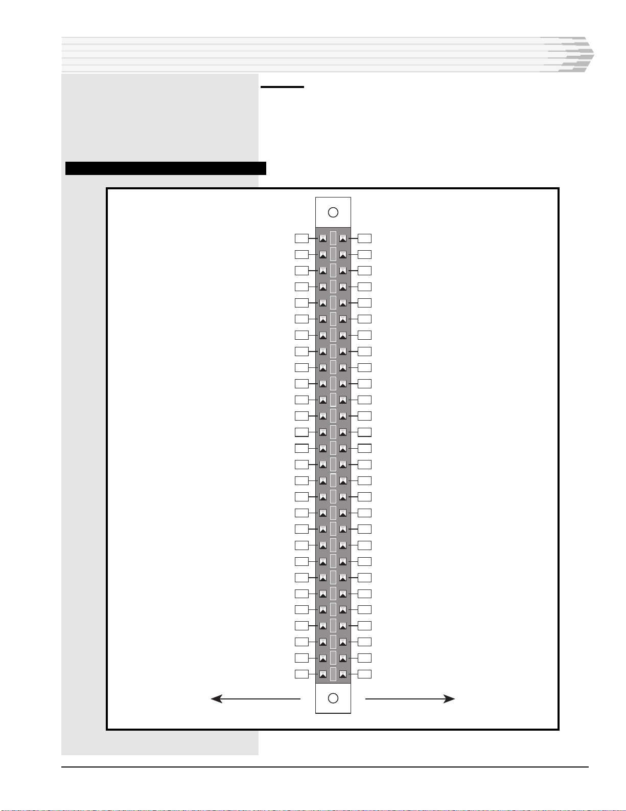
TABLE B - SWITCH SETTINGS, 44202 MODEM
* NOTE: Normal setting is for Bell 202, Main Loopback.

44202-0898<90-00004> PAGE 9
INSTALLATION
Wiring
In most cases, the 56-pin edge connector is prewired at the factory.
If custom wiring is required, refer to Fig. 4 for module edge
connector pin designations, or contact Dantel. Wire the connector
in the shelf or housing as required.
FIG. 4 - PIN DESIGNATIONS, 44202 MODEM
56 55
54 53
52 51
50 49
48 47
46 45
44 43
42 41
40 39
38 37
36 35
34 33
32 31
30 29
28 27
26 25
24 23
22 21
20 19
18 17
16 15
14 13
12 11
10 9
87
65
43
21
CIRCUIT SIDE
OF PC BOARD
COMPONENT SIDE
OF PC BOARD
Dist. Out
Sum In
ALB
DLB
4W RCV (600 ohm); 2W XMT-RCV4W RCV (600 ohm); 2W XMT-RCV
4W XMT (600 ohm)4W XMT (600 ohm)
DTR (TTL port)RTS (TTL port)
RXD (TTL port)TXD (TTL port)
CTS (TTL port)DCD (TTL port)
DSR (TTL port)
TD (RS-232 port)
DTR (RS-232 port)RTS (RS-232 port)
Ground
DCD (RS-232 port)CTS (RS-232 port)
DSR (RS-232 port)RD (RS-232 port)
RXD- (RS-422 port)RXD+ (RS-422 port)
CD- (RS-422 port)CD+ (RS-422 port)
RTS+ (RS-422 port)RTS- (RS-422 port)
TXD+ (RS-422 port)TXD- (RS-422 port)
TXD+ (RS-485 port)TXD- (RS-485 port)
RXD- (RS-485 port)RXD+ (RS-485 port)
-21 to -56 VDC
Signal Ground

PAGE 10 44202-0898<90-00004>
INSTALLATION
CONTINUED . . .
Install Module
Disconnect power to the shelf. Install the module in the proper slot
in the equipment housing by sliding the module along the guide
slots, then firmly seating connector in its receptacle.
Checkout
Checkout of the 44202 202 Compatible Modem is done by setting
the transmit and receive levels and testing the analog and digital
circuit sides using the digital and analog loopback functions. Refer
to Fig. 5 (in the Operation section of this manual) and the
following procedure.
ALIGNMENT AND CHECKOUT PROCEDURE
Alignment
1. Action: Configure the 44202 module for the appropriate application.
Ensure that power is removed from the equipment shelf. Install the
module in the designated slot.
2. Action: Apply power to the shelf.
3. Action: Connect a Transmit Measure Set (TMS) to the XMT LINE
jack on the front panel. Configure the TMS for 600 ohm terminated
measurment. A db meter can be used to make a bridged measure-
ment by connecting to the XMT MON jack.
NOTE: The XMT MON jack does not open the jack normals and the
1200 hz tone will be transmitted to a connecting circuit,
interrupting data communication.
4. Action: Place the TEST switch in the on, or up, position.
Result: The RTS and DTR LEDs are lit. A 1200 hz tone is trans-
mitted to the test set.
NOTE: A failure in step 4 indicates a lack of power or a defective
module.
5. Action: Adjust the XMT LEVEL potentiometer to reach the engi-
neered data level. Turn clockwise to raise the level; counterclockwise
to lower the level.
NOTE: If the desired level cannot be reached, remove power from the
shelf and unplug the module. Place the XMT GAIN strap in
the HIGH position to add 20dB of gain. Replace the module,
reconnect power, and adjust the XMT LEVEL pot for the
desired level.
Result: The transmitted tone is set to the desired level.
UPDATED

44202-0898<90-00004> PAGE 11
INSTALLATION
NOTE: If the transmit level cannot be adjusted, the module is defective
and should be replaced
6. Action: Connect the TMS, set for bridged reading, or a dB meter, to
the test points labeled RCV and GND. Send the engineered data
level (13dB below tone level) into the 44202 modem from an available
test point. (RCV Line, DST, CXR jack, etc.)
Result: The CD LED lights.
7. Action: Adjust the RCV GAIN pot to achieve a -20dBm meter
reading.
NOTE: If the desired level cannot be reached, remove power from the
shelf and unplug the module. Place the RCV GAIN strap in
the HIGH position to add 20dB of gain. Replace the module,
reconnect power, and adjust the RCV GAIN pot for the
desired level.
If the receive gain cannot be adjusted, the module is defective
and should be replaced.
8. Action: Remove the data level tone. Place the TEST switch in the
OFF position.
9. This completes the modem alignment.
Analog Loopback Test
1. Action: Place the ALB (analog loopback) switch and the TEST
switch in the ON position. Connect a TMS with a speaker to the
XMT LINE jack.
Result: You should hear the 1200hz data tone from the modem.
2. Action: At the distant end, have someone send data to the modem.
Result: You should hear the data they are sending along with the
1200hz tone.
3. Action: Return the ALB and TEST switches to OFF and remove
the connection to the TMS.
4. This completes the analog loopback test.
Digital Loopback Test
1. Action: Place the TEST and DLB switches in the ON (up) posi-
tion.
Result: The RTS, DTR, CTS, and CD LEDs come on.
2. Action: Configure a terminal or terminal emulator for 1200 baud, 8
bit word length, 1 stop bit, and no parity. Connect the terminal to the
RS-232 port. Type on the terminal.
Result: The TD and RD LEDs flash. The data is looped back and
the typed characters are displayed on the screen.
CONTINUED . . .
UPDATED

PAGE 12 44202-0898<90-00004>
INSTALLATION
3. Action: Remove the terminal connection and place the TEST and
DLB switches in the OFF(down) position.
4. This completes the digital loopback test and the alignment and test
procedure.
OPERATION
O
peration of the 44202 consists of turning front panel
switches OFF and ON for level setting and testing as de-
scribed in the Installation section. While the 44202 is being used
for normal data transmission, there are no user operations to be
performed.
LEDs
Six (6) green LEDs on the front panel indicate:
♦TD (Transmit Data)
♦RD (Receive Data)
♦RTS (Ready To Send)
♦CD (Carrier Detect)
♦DTR (Data Terminal Ready)
♦CTS (Clear To Send)
Each of the LEDs operates when the modems activity is appropri-
ate to the LEDs designation.
Front Panel Switches
There are three (3) recessed switches are used for testing the
modules operation. They are:
♦ON TEST
♦ON DLB
♦ON ALB
Front Panel Jacks
Two (2) normal-through jacks are provided for connecting to the
facility. These are:
♦XMT LINE
♦2W LINE
The jack labeled 2W LINE is the receive line jack. There are also
two (2) jacks labeled:
♦XMT MON
♦2W MON
FIG. 5 - FRONT PANEL VIEW
CONTINUED . . .
UPDATED
44202-00
202 MODEM
A11-44202-00 REV__
ON
TEST
MON
XMT
4W
2W
LINE
MON
LINE
ON
ABL
ON
DLB
TD RD
RTS CD
DTR CTS
XMT
LEVEL
RCV
GND
RCV

44202-0898<90-00004> PAGE 13
These are used for monitoring the facility-side transmit and
receive. The jack labeled 2W MON is the receive monitor jack.
Test Points and Potentiometers
Two (2) front panel test points are used in conjunction with the
front panel potentiometer labeled RCV LEVEL. The test points are
labeled:
♦RCV
♦GND
They provide a means of adjusting the receive level at the modem
IC. The other potentiometer is labeled XMT LEVEL, and is used to
set the transmit level at the XMT LINE jacks on the front panel.
OPERATION

PAGE 14 44202-0898<90-00004>
TECHNICAL SPECIFICATIONS
DESCRIPTION
POWER REQUIREMENTS
Input Voltage
Input Current
Idle
Busy
Heat Dissipation (max)
AUDIO PORT LEVELS (600 OHMS)
XMT Carrier Level
RCV Carrier Level
RCV Path Gain
RCV Path Attenuation
DIGITAL INTERFACES
TTL/CMOS
Input Voltage
Output Current
RS-232 Receivers
Input High Voltage
Input Low Voltage
RS-232 Drivers
Output High Voltage
Output Low Voltage
Short Circuit Current
Output Resistance
Max. Load Resistance
RS-422 and RS-485 Receivers
Differential Input
Common Mode Input
RS-422 and RS-485 Drivers
Differential Output Voltage
Short Circuit Current
Max. Load Resistance
ALB AND DLB INPUTS
Operating Voltage
Disable Voltage
PHYSICAL FEATURES
Weight
Dimensions
Operating Temperature Range
VALUES
-21 to -56 VDC
@ -21 VDC @ -24 VDC @ -48 VDC @ -56 VDC
120 mA 105 mA 75 mA 70 mA
135 mA 120 mA 85 mA 80 mA
@ -21 VDC @ -24 VDC @ -48 VDC @ -56 VDC
9.7 Btu/Hr 9.9 Btu/Hr 14.0 Btu/Hr 15.3 Btu/Hr
-35 dBm min. to +7 dBm max.
-40 dBm min. to 0 dBm max.
24 dB
26 dB
0 to 1 V = Low; 3.4 to 5 V = High
16 mA Sink, Open Drain (high out)
+3 to +25 V
-3 to -25 V
10.5 V typical; 9 V min. w/3K ohm load
9.5 V typical w/ no load; 8 V min. w/ 3K ohm load
+45 mA max.
300 ohms min.
3K ohms
+0.2 V threshold, voltage referenced to inverting input
+12 V max., voltage referenced to ground
+4 V max., no load; +1.5 V min., 54 ohm load, ref. @ inverting output
+150 mA, Vo = Vcc; -150 mA, Vo = 0
54 ohms
0 to 1 V
3.4 to 5 V or open
9 ounces
1.4" x 6.0" x 5.6"
0° to 55° C.

44202-0898<90-00004> PAGE 15
NOTES

PAGE 16
16PAGES 44202-0898<90-00004>
LIMITED WARRANTY
The Seller warrants that the standard hardware products sold will be free from defects in material and workman-
ship and perform to the Sellers applicable published specifications for a period of 18 months for hardware, and 3
months for software, from the date of the original invoice. The liability of the Seller hereunder shall be limited to
replacing or repairing, at its option, any defective products which are returned F.O.B. to the Sellers plant, (or, at
the Sellers option, refunding the purchase price of such products). In no case are products to be returned without
first obtaining permission and a customer return authorization number from the Seller. In no event shall the
Seller be liable for any consequential or incidental damages.
Equipment or parts which have been subject to abuse, misuse, accident, alteration, neglect, unauthorized repair
or installation are not covered by warranty. The Seller shall make the final determination as to the existence and
cause of any alleged defect. No warranty is made with respect to custom equipment or products produced to the
Buyers specifications except as specifically stated in writing by the Seller in the contract for such custom equip-
ment.
This warranty is the only warranty made by the Seller with respect to the goods delivered hereunder, and may be
modified or amended only by a written instrument signed by a duly authorized officer of the Seller and accepted by
the Buyer.
Warranty and remedies on products not manufactured by the Seller are in accordance with warranty of the
respective manufacturer. THE SELLER MAKES NO OTHER WARRANTY OF ANY KIND WHATSOEVER,
EXPRESSED OR IMPLIED; AND ALL IMPLIED WARRANTY OF FITNESS FOR A PARTICULAR PURPOSE
WHICH EXCEEDS THE AFORESAID OBLIGATIONS IS HEREBY DISCLAIMED BY THE SELLER.
INCASE OF DIFFICULTY
If you experience difficulty with this equipment, check the following, as appropriate:
1. Switch settings
2. Signal levels
3. Software configuration
4. Connections between Dantel’s equipment and your equipment.
If there is still a problem, substitute equipment that is known to be good. For additional assistance, call Dantels
Technical Field Service Department weekdays, 6 A.M. to 5 P.M. pacific time:
1-800-4DANTEL(1-800-432-6835).
If a thorough checkout shows a piece of equipment has malfunctioned, you may return it to the factory. For
repairs and emergency replacements, obtain a Return Material Authorization (RMA) number from the Customer
Service Representative at 1-800-4DANTEL (1-800-432-6835).
To ensure expedient processing of your order, provide a purchase order number and shipping and billing informa-
tion when requesting an RMA number. Also, when the units are returned to Dantel, include a description of the
failure symptoms for each unit returned. Send defective equipment to:
Dantel,Inc. • 2991NorthArgyleAvenue • Fresno,California93727-1388
P.O. Box 55013 • Fresno, CA 93747-5013 Phone (209) 292-1111 Fax (209) 292-9355 http://www.dantel.com
WARRANTY
This manual suits for next models
1
Table of contents
Other Dantel Modem manuals