Dantel 44214 User manual

CAUTION
•Install or remove modules from the shelf only when the power is off.
If you install a module in the shelf with the power on, the internal
circuitry may suffer damage and the product warranty will be void.
•Remove and install circuit boards only in a static-safe environment
(use antistatic wrist straps, smocks, footwear, etc.).
•Keep circuit boards in their antistatic bags when they are not in use.
•Do not ship or store circuit boards near strong electrostatic, electromag-
netic, magnetic, or radioactive fields.
•For more complete information on electrostatic discharge safety
precautions, refer to BellcoreTM Technical Reference # TR-NWT-000870.
Copyright 1998 by Dantel, Inc. • Dantel is a registered trademark of Dantel, Inc. • ISO 9001 Registered
Printed in the U.S.A.
INSTALLATION & OPERATION MANUAL
44214-0898 <90-00005>
44214
9600 BPS MODEM
About this Practice:
This practice has been reissued to:
• Update Figs. 1 and 3.
Issue date: August 1998
Reissued Practices: Updated and
new content can be identified by a
banner in the right margin.
UPDATED
Table of Contents
Ordering Information ........................................................................... 2
General Description.............................................................................. 2
Circuit Description ............................................................................... 3
Installation............................................................................................ 5
Operation ............................................................................................ 10
Application Information ..................................................................... 10
Technical Specifications ..................................................................... 12
Warranty ............................................................................................. 14

PAGE 2 44214-0898 <90-00005>
ORDERING INFORMATION
NOTE: This section lists the different options available for this product. To order any of the avail-
able options, contact Dantel Inside Sales through our toll-free number, 1-800-432-6835.
OPTION NUMBER FEATURES
A11-44214-00 9600 bps Tone Modem
GENERAL DESCRIPTION
The A11-44214-00 9600 bps Modem is a 400-type module used
in applications where a tone modem is required. This module
provides an interface between Data Terminal Equipment (such
as a computer or terminal) and a 4-wire voice channel (such as
a mux channel or a satellite link). Capable of transmitting and
receiving data at 1200, 2400, 4800, or 9600 bps, this module
converts asynchronous data from a serial bit stream into voice-
frequency tone in one direction and tone to serial data in the
other direction.
On the data side of the 44214 there are input/output ports
available for interfacing to Data Terminal Equipment. Available
interfaces are:
♦TTL/CMOS
♦RS232
♦RS422
♦RS485
An on-board switch (S6) selects which interface is enabled.
The front panel provides:
♦Four mini jacks for 4-wire level adjustments and testing.
♦Six green LEDs that indicate communication status.
♦Switches for testing the modem, and selecting the mode of
operation.
♦Potentiometers for adjusting the transmit and receive levels.
NOTE:
The 44214 must communicate
with another 44214. Using on-
board switches, set the baud rate
of both modules the same.
NOTE:
Only one interface may be en-
abled at a time.
NOTE:
The A11-44214-00 4-Wire Modem
is not Bell 202 compatible.

44214-0898 <90-00005> PAGE 3
CIRCUIT DESCRIPTION
Fig. 1 shows the 44214 9600 bps Modem functional schematic.
The circuit contains:
♦87C51 Microcontroller
♦Loopback capability
♦Modem Controller
♦Reset circuitry
♦Asynchronous Serial Interface
♦Analog Interface
87C51 Microcontroller
The microcontroller is used to configure and operate the modem
controller and operates at 12 Megahertz. This processor contains
a one-time programmable ROM and 128 bytes of data RAM. A
two-position switch (S4) configures the microprocessor to oper-
ate in either originate or answer mode. When configured in
originate mode, the modem constantly transmits an origination
tone on the analog line. When in answer mode, it continually
monitors the line for an origination tone and responds if one is
detected. For two modems to communicate over the orderwire,
one device must be in originate and the other in answer mode.
Loopback
Both the analog and digital sides of the 44214 can be set to
loopback. A two-position switch (S3) is used to enable or disable
the analog side. A second two-position switch (S5) is used to
enable or disable the digital side.
Modem Controller
The modem controller provides all the modem functions. It
includes the analog modulation/demodulation, analog to digital
conversion, asynchronous serial data signal control, and configu-
ration. Receiving configuration information from the micro-
controller, the modem controller drives the asynch digital
interface as well as the analog line interface. The transformers
are 600-to-442 ohm and provide facility-side to circuit isolation.
Reset Circuit
The modem can be reset by a push button (S1), which can be
accessed through the front panel. There is also a watchdog
circuit that will reset the modem if there is no activity from the
microprocessor for 1.2 seconds.
NOTE:
Upon power-up, the modem con-
figured for answer-mode will
transmit a continuous answer
tone and will respond if an origi-
nate tone is detected. If an origi-
nate tone is not detected within
10 seconds of power-up, it will
stop transmitting the answer
tone and will wait. Upon receiv-
ing an originate tone, it wil start
transmitting an answer tone
again.

PAGE 4 44214-0898 <90-00005>
FIG. 1 - FUNCTIONAL SCHEMATIC; 44214 4-WIRE MODEM
CIRCUIT DESCRIPTION
UPDATED
TD
GROUND
35
17
ALB
DLB
MODE
DATA
RATE
RD
CTS
CD
RTS
DTR
S3
S5
+5
VDC
S2
I/O
GATING
&
DRIVERS
I/O
GATING
&
DRIVERS
I/O
GATING
&
DRIVERS I/O
GATING
&
DRIVERS
MICRO
CONTROLLER
MODEM
CONTROLLER
NOTE: The following are accessible
through the front panel:
S1, S3, S4, S5, R44, R53
S4
+5VDC
JP4
JP5 RTS
DTR
INTERFACE
ENABLE
JP1
S6
TO
JP2
TTL /
CMOS
SIGNAL
GROUND
RS-232
RS-422
DTR
RTS
TD
RD
CD
CTS
DSR
TD
DTR
CTS
RTS
CD
RD
DSR
TX+
TX-
RTS+
RTS-
CD+
RX+
RX-
CD-
I/O
GATING
&
DRIVERS
REGULATED
POWER
SUPPLY
RX+
TX+
TX-
RX-
RS-485
-21 TO -56 VDC +5 VDC
SOURCE
-12 VDC SOURCE
+12 VDC SOURCE
TO
JP3
RING
TIP
RING
TIP
4W XMT RCV
-or-
2W LINE
4W XMT
R44
R53
ANALOG
CIRCUIT
39
40
42
41
3
4
2
1
10
9
5
6
12
11
7
8
13
14
16
19
20
21
15
27
28
30
32
29
26
25
31
TO
RESET
S1
S7
2W/4W
47
ALB
DLB 45

44214-0898 <90-00005> PAGE 5
Asynchronous Serial Interface
The asynchronous serial interface provides the drivers and
switching capability to support RS232, RS422, RS485, or TTL
communication. The selection of interface is accomplished using
S6. There is an LED display which indicates activity on the
TXD, RXD, CTS, RTS, DTR, and CD lines.
Analog Interface
The analog interface provides the 2 or 4-wire circuitry necessary
to communicate with the modem controller. A two-position
switch (S7) selects 2-wire or 4-wire operation. Transmit and
receive levels are independently adjustable from the front panel.
XMT and RCV levels are adjustable from -40dBm to 0dBm.
CIRCUIT DESCRIPTION
NOTE:
For 2-Wire operation, the trans-
mit level will adjust itself to the
best level between -30dBm and
0dBm.
INSTALLATION
Installation consists of setting the switch and strap settings,
wiring the pin connectors, installing the module in the shelf,
and checking out the module.
1. Set the switch and strap settings
Set switches with the on-board slide switches, mini-DIPs or
recessed front panel slide switches. Refer to Fig. 2, Fig. 3, and
Table A.
Set straps with the on-board mini-jumpers. Refer to Fig. 3 and
Table B.
2. Install the module in the shelf
Install the module in the proper slot by sliding the module along
the guide slots, then firmly seating the edge connector in its
receptacle.
ALIGNMENT PROCEDURE
Set modem to Originate Mode
Set Switch 4, accessible through the front panel, to ORG.
Adjust transmit level
Connect a 600 ohm terminated dB meter to the module.
Connection can be made at either of two places. A mini-plug
can be inserted into the front panel jack labeled 4W MON or
the meter can be connected to the 44214’s edge connector at
pins 40 and 39.

PAGE 6 44214-0898 <90-00005>
Adjust the XMT LEVEL, at the bottom of the front panel, until
the meter reads -6dBm.
Adjust the receive level
Connect a 600 ohm load across the output of a signal generator.
With a 600 dB meter across those same outputs, adjust the
output level of the generator until the meter reads -29 dBm, at
1004 Hz.
Remove the meter and the 600 ohm load from the generator.
Connect the generator to the 44214. Connection can be made at
either of two places. A mini-plug can be inserted into the front
panel jack labeled 2W LINE or the meter can be connected to
the 44214’s edge connector at pins 41 and 42.
Connect the dB meter, unterminated, to the pinjacks on the
front panel. These are labeled RCV and GND.
Adjust the RCV LEVEL, at the bottom of the front panel, until
the meter reads -20 dBm.
Remove the meter and the generator.
CHECKOUT PROCEDURE
Follow the Alignment Procedure to set the levels. If, at any point
in the alignment, the unit fails, the module should be replaced.
When performing the checkout procedure described below, take
appropriate precautions to avoid damaging the unit. Wear an
ESD wriststrap, and make sure it is grounded. Every time the
procedure requires that the module be removed from the shelf or
replaced in the shelf, remove power from the entire shelf.
RTS/DTR
Remove power and set JP4 to ACT. Replace the module and
restore power. The front panel DTR LED will illuminate. Re-
place JP4 to position NA. The DTR LED will remain off.
Remove power and set JP5 to ACT. Replace the module and
restore power. The front panel RTS LED will illuminate. Re-
place JP5 to position NA. The RTS LED will remain off.
Analog Loopback (ALB)
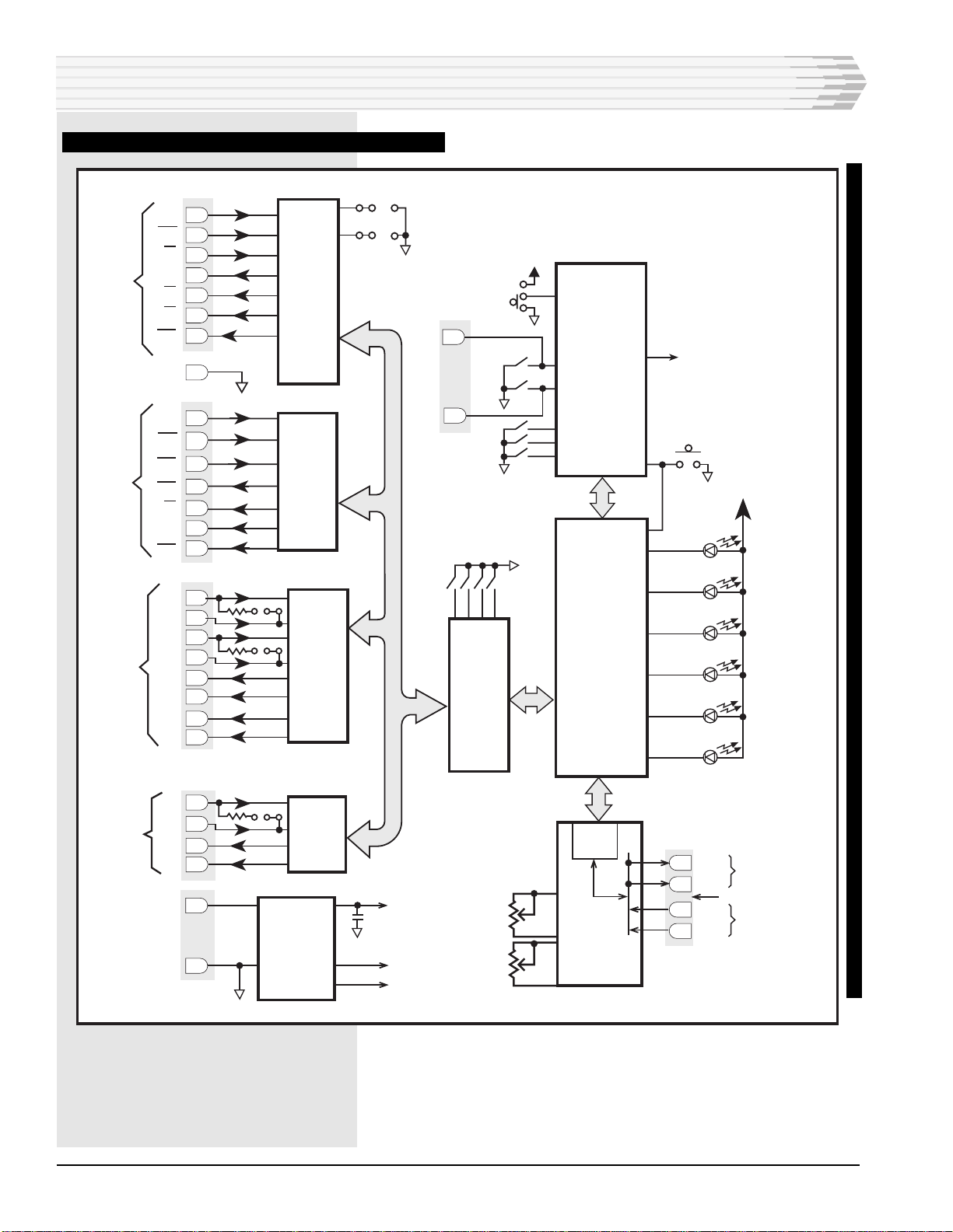
Set S6-1 on, and the rest off. This enables the RS232 portion of
the modem. Connect a dumb terminal to the RS232 port. Refer
to Figure 1. Edge connector pin 21 is the transmit into the
44214. Pin 14 is the receive back to the dumb terminal. Use
pin 17 or 25 for signal ground.
Set ALB, on the front panel, to ON. After a delay of 5 seconds,
the front panel RTS, DTR, CD, and CTS LEDs will come on.
Typing on the keyboard will cause the TD and RD LEDs to blink
and the characters to be echoed back on the screen.
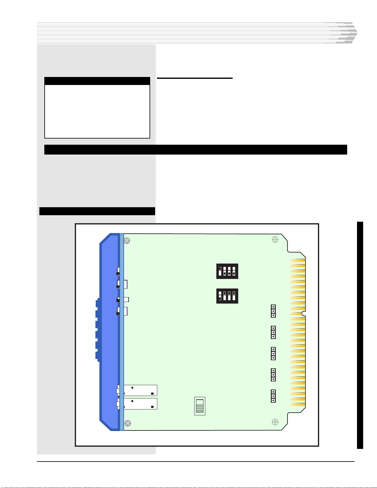
LINE
MON
LINE
MON
TD RD
RTS CD
DTR CTS
2W
XMT
4W
XMT
RCV
LEVEL
GND
ON
OFF
ON
OFF
ORG
ANS
RCV
RST
ALB
DLB
44214-00 REV__
44214-00
9600 BPS MODEM
FIG. 2 - FRONT PANEL VIEW
NOTE:
During normal operation, the an-
alog loopback function is used to
test the facility between the mo-
dem and the DTE device connect-
ed to the modem. The ALB func-
tion can also be activated by ap-
plying a signal ground to edge
connector pin 47.
CONTINUED . . .
INSTALLATION

44214-0898 <90-00005> PAGE 7
Set ALB to OFF.
Return S6 to the setting required by the application in use.
Digital Loopback (DLB)
Connect a remote modem to the analog side. Set DLB, on the
front panel, to ON. After a delay of 5 seconds, the remote
modem's front panel RTS, DTR, CD, and CTS LEDs will come
on. Type any character on the remote terminal. The remote
modem’s TD and RD LEDs will blink and the remote terminal
will receive its character back.
FINAL CHECK-OUT
For the two modems to communicate with each other, one must
be set to ORG mode and the other to ANS. These switches are on
the front panel of each unit. Make sure that the 2W/4W switch
(S7) is set per the application.
FIG. 3 - STRAP AND SWITCH LOCATIONS
NOTE:
During normal operation, the
digital loopback function is used
to test the facility between the
modems. The DLB function can
also be activated by applying a
signal ground to edge connector
pin 45.
INSTALLATION
S2
1234
S7
R44
R53
S3
S5
S1
S4
S6
1234
OUT
IN
JP1
OUT
IN
JP2
OUT
IN
JP3
ACT
N/A
JP4
ACT
N/A
JP5
4W
2W
OFF
ON
OFF
ON
UPDATED

PAGE 8 44214-0898 <90-00005>
SWITCH
S1
S2
S2
S3
S4
S5
S6*
S7
POSITION
Momentary
Bit 1 Bit 2 Bit 3
ON ON ON
OFF ON ON
ON OFF ON
OFF OFF ON
ON ON OFF
OFF ON OFF
ON OFF OFF
OFF OFF OFF
Bit 4 ON
Bit 4 OFF
ON
OFF
ORG
OFF
ON
OFF
Bit 1 ON
Bit 2 ON
Bit 3 ON
Bit 4 ON
4W
2W
DESCRIPTION
Momentary reset button
Non-functional
9600 baud operation
7200 baud operation
4800 baud operation
2400 baud operation
1200 baud operation
Non-functional
Non-functional
No parity
Even parity
Enable analog loopback
Disable analog loopback
Set modem to Originate Mode
Set modem to Answer Mode
Enable digital loopback
Disable digital loopback
RS-232 I/O Port enabled
TTL/CMOS I/O Port enabled
RS-422 I/O Port enabled *
RS-485 I/O Port enabled *
4-Wire operation
2-Wire operation
* NOTE: Enable only one I/O port at a time. JP4 and JP5 must
be strapped to ACT if RS-422 or RS-485 is enabled.
STRAP
JP1
JP2
JP3
JP4
JP5
POSITION
OUT
IN
OUT
IN
OUT
IN
1 & 2
2 & 3
1 & 2
2 & 3
DESCRIPTION
No termination at RS-422 Transmit Data Input
180 ohm termination at RS-422 Transmit Data Input
No termination at RS-422 RTS Input
180 ohm termination at RS-422 RTS Input
No termination at RS-485 Transmit Data Input
180 ohm termination at RS-485 Transmit Data Input
Activated / DTR (*required for RS-422 or RS-485)
Not activated
Activated / RTS (*required for RS-422 or RS-485)
Not activated
INSTALLATION
TABLE A - SWITCH SETTINGS
TABLE B - STRAP OPTIONS

44214-0898 <90-00005> PAGE 9
INSTALLATION
56 55
54 53
52 51
50 49
48 47
46 45
44 43
42 41
40 39
38 37
36 35
34 33
32 31
30 29
28 27
26 25
24 23
22 21
20 19
18 17
16 15
14 13
12 11
10 9
87
65
43
21
CIRCUIT SIDE
OF PC BOARD
COMPONENT SIDE
OF PC BOARD
Reserved
Reserved
Reserved
Reserved
ALB (TTL)
DLB (TTL)
4-Wire RCV or 2-Wire XMT/RCV4-Wire RCV or 2-Wire XMT/RCV
4-Wire XMT4-Wire XMT
-21 to -56 VDC
DTR (TTL)RTS (TTL)
RD (TTL)TD (TTL)
CTS (TTL)CD (TTL)
Signal GroundDSR (TTL)
TD (RS-232)
DTR (RS-232)RTS (RS-232)
Ground
CD (RS-232)CTS (RS-232)
DSR (RS-232)RD (RS-232)
RX- (RS-422)RX+ (RS-422)
CD- (RS-422)CD+ (RS-422)
RTS+ (RS-422)RTS- (RS-422)
TX+ (RS-422)TX- (RS-422)
TX+ (RS-485)TX- (RS-485)
RX- (RS-485)RX+ (RS-485)
When it is necessary to wire directly to the 44214 4-Wire Mo-
dem, refer to Fig. 4 for the pin designation.
FIG. 4 - PIN DESIGNATIONS

PAGE 10 44214-0898 <90-00005>
Applications for the 44214 9600 bps Modem consist of digital
data transmission service between distant equipment sites.
Use the 44214 with equipment from other manufacturers (for
example, alarm and control) to transmit and receive data be-
tween a remote location and central location.
Fig. 5 shows a 44214 Modem application. A 44214 Modem at a
remote location transmits 460 Alarm and Control System data to
a 44214 Modem at a central data processing location. The 44214
Modem provides stable operation because its battery, a DC
power source, is free of AC power interruptions.
Fig. 6 shows a 44214 Modem used in the 05547 DTSS3A
Orderwire\Data Interface. In this application the 44214 pro-
vides a 9600 bps interface between a piece of Data Termination
Equipment and Dantel’s DTSS3A Orderwire. The 05547 then
provides two-way voice and/or data communication over a
64-Kilobit Channel. At the far end is another 05547 equipped
with another 44214 9600 bps Modem.
OPERATION
For the most part, once the switches, straps, and levels have
been set, operation of the 44214 9600 bps Modem consists of
observing the front panel LEDs.
Six green LEDs on the 44214 front panel indicate:
♦TD (Transmit Data)
♦RD (Receive Data)
♦RTS (Request To Send)
♦CD (Carrier Detect)
♦DTR (Data Terminal Ready)
♦CTS (Clear To Send)
There are two recessed switches labeled ALB-ON/OFF and
DLB-ON/OFF. These switches test the modem’s operation.
There is one recessed switch labeled ORG-ANS. This switch sets
the mode of operation for the modem.
Two normal-through mini jacks, labeled 4W LINE (transmit
line) and 2W LINE (receive line), provide facility connection.
Two jacks, labeled 4W MON (transmit monitor jack) and
2W MON (receive monitor jack), monitor facility-side transmit
and receive.
The RCV level potentiometer adjusts the modem IC receive
level. The XMT LEVEL potentiometer sets the transmit level at
the XMT LINE jacks.
LINE
MON
LINE
MON
TD RD
RTS CD
DTR CTS
2W
XMT
4W
XMT
RCV
LEVEL
GND
ON
OFF
ON
OFF
ORG
ANS
RCV
RST
ALB
DLB
44214-00 REV__
44214-00
9600 BPS MODEM
APPLICATION INFORMATION
IMPORTANT NOTE:
When used in alarm applications,
as depicted in Fig. 5, the 44214
has specific limitations.
The 44214 may only be used at
9600 baud.
The 44214 modem may only be
used on point-to-point (not
bridged) circuits.
The 44214 modem may only be
used with one other 44214 mo-
dem operating at 9600 baud.

44214-0898 <90-00005> PAGE 11
FIG. 5 - EXAMPLE APPLICATION 1
APPLICATION INFORMATION
CENTRAL LOCATION
TO
ALARM
CENTER
CONTROL
POINT
MODULE
MULTI
ALARM
TRANS-
MITTERS
MULTI-
ALARM
PROCESSOR
44214
4-WIRE
MODEM
44214
4-WIRE
MODEM
CONTROL
OUTPUTS
DEDICATED
COPPER PAIR
REMOTE LOCATION
LOCAL
MONITORING
AND CONTROL
DISCRETE
ALARM
POINTS
FIG. 6 - EXAMPLE APPLICATION 2
41096-01 41096-01
MASTER (CALLING) TERMINAL
DATA CIRCUIT
REMOTE (CALLED) TERMINAL
FIBER
OPTIC
TERM
4
6
1
0
5
FIBER
OPTIC
TERM
4
6
1
0
5
FIBER
TERMINAL
EXTERNAL
4-WIRE
MODEM
B18-05547-01
A11-44214-00
B18-05547-01
4
6
1
0
5
4
6
1
0
5
FIBER
OPTIC
TERM
FIBER
OPTIC
TERM
CH 1
VOICE CIRCUIT
STATION 1 CODESTATION 1 CODE
CH 1

PAGE 12 44214-0898 <90-00005>
TECHNICAL SPECIFICATIONS
CONTINUED . . .
DESCRIPTION
POWER REQUIREMENTS
Input Voltage
Input Current
@ -21 VDC
@ -24 VDC
@ -48 VDC
@ -56 VDC
Maximum Heat Dissipation
@ -21 VDC
@ -24 VDC
@ -48 VDC
@ -56 VDC
HARDWARE STANDARDS
Physical Size
Weight
Operating Temperature
AUDIO PORT LEVELS (600 OHM)
XMT Carrier Level
RCV Carrier Level
DIGITAL INTERFACES
TTL/CMOS
Input Voltage
Output Current
RS-232
Receivers
Input High Voltage
Input Low Voltage
Drivers
Output High Voltage
Output Low Voltage
Short Circuit Current
Output Resistance
Maximum Load Resistance
RS-422 & RS-485
Receivers
Differential Input
Common Mode Input
Drivers
Differential Output
Short Circuit Current
ALB & DLB Inputs
Operating Voltage
Usable Voltage
VALUE
-21 to -56 VDC
114 mA
100 mA
48 mA
45 mA
8.9 Btu/Hr
8.9 Btu/Hr
9.0 Btu/Hr
9.4 Btu/Hr
1.4"H x 6.0"L x 5.6"W
8.14 ounces
0° to 55° C.
-40 dBm min. to 0 dBm max.
0 to +1V = Low; +3.4 to +5V = High
6mA Sink
+3 to +25V
-3 to -25V
+10.5V typ.; +5V min. (3K ohm load)
-9.5V typ. (no load); -5V min. (3K ohm load)
+30 mA max.
300 ohms min.
3K ohms
+0.2V threshold; voltage ref. to inverting input
+12V max.; voltage ref. to ground
+4V max. (no load)
+1.5V min. (54 ohm load at inverting output)
180 mA V54 = VCC
-180 mA Vo = -7V
500 mA Vo = +17V
0 to +1V
+3.4 to +5V
TECHNICAL SPECIFICATIONS; 44214 4-WIRE MODEM

44214-0898 <90-00005> PAGE 13
TECHNICAL SPECIFICATIONS
Configuration Mode
Modulation
Carrier Frequency +0.01
Baud (Symbol/Sec.)
Bits Per Symbol Data/TCM
Constellation Points
9600
V.32 9600
QAM
1800
2400
4/0
16
7200
V.32 TCM
TCM
1800
2400
3/1
16
4800
V.32 4800
QAM
1800
2400
2/1
4
2400
V.22 BIS 2400
QAM
1200/2400
600
4/0
16
1200
V.22 BIS 1200
KPSK
1200/2400
600
2/0
4
TECHNICAL SPECIFICATIONS (CONTINUED); 44214 4-WIRE MODEM

PAGE 14
14 PAGES 44214-0898 <90-00005>
LIMITED WARRANTY
The Seller warrants that the standard hardware products sold will be free from defects in material and work-
manship and perform to the Seller’s applicable published specifications for a period of 18 months for hardware,
and 3 months for software, from the date of the original invoice. The liability of the Seller hereunder shall be
limited to replacing or repairing, at its option, any defective products which are returned F.O.B. to the Seller’s
plant, (or, at the Seller’s option, refunding the purchase price of such products). In no case are products to be
returned without first obtaining permission and a customer return authorization number from the Seller. In
no event shall the Seller be liable for any consequential or incidental damages.
Equipment or parts which have been subject to abuse, misuse, accident, alteration, neglect, unauthorized
repair or installation are not covered by warranty. The Seller shall make the final determination as to the
existence and cause of any alleged defect. No warranty is made with respect to custom equipment or products
produced to the Buyer’s specifications except as specifically stated in writing by the Seller in the contract for
such custom equipment.
This warranty is the only warranty made by the Seller with respect to the goods delivered hereunder, and may
be modified or amended only by a written instrument signed by a duly authorized officer of the Seller and
accepted by the Buyer.
Warranty and remedies on products not manufactured by the Seller are in accordance with warranty of the
respective manufacturer. THE SELLER MAKES NO OTHER WARRANTY OF ANY KIND WHATSOEVER,
EXPRESSED OR IMPLIED; AND ALL IMPLIED WARRANTY OF FITNESS FOR A PARTICULAR PUR-
POSE WHICH EXCEEDS THE AFORESAID OBLIGATIONS IS HEREBY DISCLAIMED BY THE SELLER.
INCASE OF DIFFICULTY
If you experience difficulty with this equipment, check the following, as appropriate:
1. Switch settings
2. Signal levels
3. Software configuration
4. Connections between Dantel’s equipment and your equipment.
If there is still a problem, substitute equipment that is known to be good. For additional assistance, call
Dantel’s Technical Field Service Department weekdays, 6 A.M. to 5 P.M. pacific time:
1-800-4DANTEL(1-800-432-6835).
If a thorough checkout shows a piece of equipment has malfunctioned, you may return it to the factory. For
repairs and emergency replacements, obtain a Return Material Authorization (RMA) number from the Cus-
tomer Service Representative at 1-800-4DANTEL (1-800-432-6835).
To ensure expedient processing of your order, provide a purchase order number and shipping and billing
information when requesting an RMA number. Also, when the units are returned to Dantel, include a descrip-
tion of the failure symptoms for each unit returned. Send defective equipment to:
Dantel, Inc. • 2991 North Argyle Avenue • Fresno, California 93727-1388
P.O. Box 55013 • Fresno, CA 93747-5013 Phone (209) 292-1111 Fax (209) 292-9355 http://www.dantel.com
WARRANTY
This manual suits for next models
1
Table of contents
Other Dantel Modem manuals