manuals.online logo
Brands
  1. Home
  2. •
  3. Brands
  4. •
  5. Dantherm
  6. •
  7. Air Handler
  8. •
  9. Dantherm AC-M5 W MKII User manual

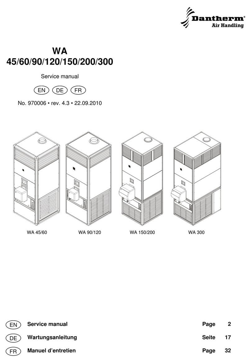
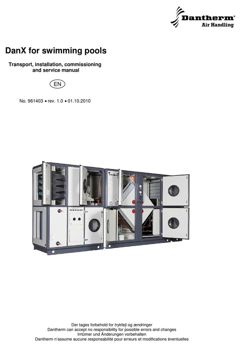
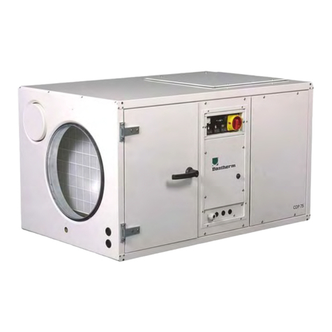
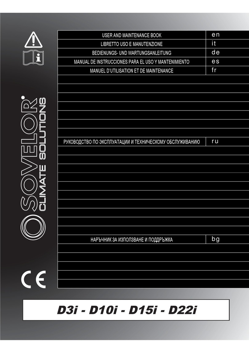
Dantherm AC-M5 W MKII User manual

DA
Betjeningsvejledning DVC-styring Side 3
EN
User’s guide for the DVC controller Page 23
DE
FR
AC-M5 W MKII
Service manual
EN
No. 062367 • rev. 1.0 • 15.02.2011
Der tages forbehold for trykfejl og ændringer
Dantherm can accept no responsibility for possible errors and changes
Irrtümer und Änderungen vorbehalten
Dantherm n’assume aucune responsabilité pour erreurs et modifications éventuelles
3
062367 • Version 1.0 • 14.02.2011
Introduction
Overview
Introduction This is the service manual for the Dantherm Air Handling A/S AC-M5 W MKII unit.
The below table of contents gives an overview of the main sections.
Serial number This manual covers units with serial numbers equal or higher than:
XXXXXX1158513
Syntax Please note that this unit comes as standard with a 2 KW heating element installed:
Dantherm number Code*) NATO stock number
322036 AC-M5WE-H020-B-BS381C285 -
*) The code is specified on the data plate, which is placed on the outside of the unit. See
the explanation of the syntax code on page 5
Warning It is the responsibility of the operator to read and understand this service manual
and other information provided and to use the correct operating procedures.
Air conditioners should only be operated by qualified (trained) personnel and the repair
of the cooling circuit and electrical system is to be done only by skilled service people.
Failure to do so can result in personal injury or equipment damage.
Read the entire manual before the initial start-up of the air conditioner. It is important to
know the correct operating procedures for the air conditioner and all safety precautions
to prevent the possibility of property damage and/or personal injury.
Table of contents This service manual covers the following main topics:
Topic See page
General information 4
Syntax 5
Product description 6
Functional description 15
User’s guide 16
Service guide 25
Technical information 36
4
General information
Introduction This section gives the general information about this service manual and about the unit.
Manual, part
number Part number of this service manual is 062367.
Target group The target groups for this service manual are the:
•Users of the unit
•Technicians who install and maintain the unit
Copyright Copying of this service manual, or part of it, is forbidden without prior written permission
from Dantherm Air Handling A/S.
Reservations Dantherm Air Handling A/S reserves the right to make changes and improvements to
the product and the service manual at any time without prior notice or obligation.
EC-Declaration of
Conformity
Dantherm Air Handling A/S, Marienlystvej 65, DK-7800 Skive hereby declare that the
units mentioned below: AC-M5 W MKII, product no. 322036:
are in conformity with the following directives:
2006/42/EEC Directive on the safety of machines
2006/95/EEC Low Voltage Directive
2004/108/EEC EMC Directive
97/23/EEC The Pressure Equipment Directive
94/62/EEC Packaging Directive
- and are manufactured in conformity with the following harmonized standards:
EN 12100 Machine Safety
EN 60 335-1 Low Voltage
EN 60 335-2-40 Low Voltage
DEF-STAN 59-411,
part 3 Land Class C Military EMC Standard
EN 378 Refrigeration systems
Skive, 16.09.2009
Recycling The unit is designed to last for many years. When the time comes for the unit to be re-
cycled, the unit should be recycled according to national rules and procedures to pro-
tect the environment.
Quality Manage-
ment System Dantherm Air Handling A/S has implemented a Quality Management System according
to EN/ISO9001. The system is supplemented with an Environmental Management Sys-
tem according to EN/ISO14001. Both systems are third-part approved and certified, by
Bureau Veritas Certification.
During 2005 & 2006 the Management Systems are supplemented with business-
routines with regards to Safety. These routines fulfil the requirements stated in the in-
ternational standard for Safety Management Systems OHSAS18001.
5
062367 • Version 1.0 • 14.02.2011
Syntax
Introduction All products are named according to a syntax giving information about the specific unit
configuration.
Example This example is not necessarily related to the specific unit this manual describes:
AC-M5W-H070-B-225-R6014-G3F7-SH-X1
AC Air conditioner
VA Heater (diesel)
M Military unit
5 5 kW nominal performance
W Window mount
S Split unit
H Electric heat
020 2000 W heat
070 7000 W heat
100 10000 W heat
200 20000 W heat
A 1 ph; 115 V AC; 60 Hz
B 1 ph; 230 V AC; 50 Hz
C 1 ph; 230 V AC; 60 Hz
D 3 ph; 230 V AC; 60 Hz
E 3 ph; 460 V AC; 60 Hz
F 3 ph; 400 V AC; 50 Hz
225 225 mm connection
315 315 mm connection
400 400 mm connection
R6014 Four digit RAL colour code or
33446 FED-STD 595B code
G3F7 Two filters, one G3, one F7
S Compressor softstarter included
H HPFI included
X Specifics/custom
6
Product description
Overview
Introduction This section will give you a description of the AC-M5 W MKII and its functionality.
Content The section covers the following topics:
Topic See page
General description 7
Description of the cooling system 10
Description of the control board 12
Accessories 14
7
062367 • Version 1.0 • 14.02.2011
General description
Introduction This section gives a description of the unit as a whole. The following sections describe
the different parts in detail.
General The AC-M5 W MKII air conditioner is made of high quality materials and the production
process is subject to constant quality checking. The instructions in this service manual
have been prepared to ensure that, when followed, this air conditioner will provide long
and efficient service.
Typical applica-
tions The AC-M5 W MKII is designed to be built into a trap door system, which is mounted in
the container. Optionally in welding frame.
The AC-M5 W MKII is designed to be compatible with shelters equipped with existing
AC-M5 W.
All dimensions are translated into the new design.
This easily upgrades the container to AC-M5 W MKII.
Dantherm air conditioner model AC-M5 W MKII is designed primarily to deliver cooling
or heating to containers and other types of temporary shelters.
Other typical applications can be:
•Cooling of hot confined areas where personnel are working
•Cooling of equipment to prevent damage or malfunction due to overheating
•Re-circulating air in closed shelters
Functionality The function of the AC-M5 W MKII is based on a cooling circuit and two powerful fans.
The front section (internal) contains the evaporator and the evaporator fan, which draws
warm ambient or re-circulated air through the cold evaporator coil and blows out the
cooled air through the discharge. The back (external) section of the unit houses the
condenser fan and the condenser coil, which returns the heat taken from the indoor air
to the surrounding atmosphere.
Lifting system By means of a fork lift the air conditioner is lifted from the outside and in, into the trap
door system.
Components on the below drawing from left to right:
•Front grill
•Welding frame
•Trapdoor system
•AC-M5 W MKII
Continued overleaf
8
General description, continued
Cabinet
Front (evaporator side)
The unit is a strong construction
made in 0.9 mm sheet metal plates,
which are galvanised and protected
against corrosion.
Outside finish painting is standard
NATO green, RAL6014 with infrared
anti-reflecting qualities.
The condensate drain is located un-
der the unit. It is snapped in place
by a snaplock in the long slot at the
bottom of the unit. The drain can be
pried out using a screwdriver if
needed during service or if a hose
extension is desired.
At the front of the unit there is a re-
movable air filter for the re-
circulated air intake on the left hand
side and a discharge grill for the
cooled outlet air at the right hand
side.
The operation panel for the unit is
placed under the discharge grill for
the cooled air.
The discharge grill can be removed
for inspection and service purposes.
Rear (condenser side)
Continued overleaf
9
062367 • Version 1.0 • 14.02.2011
General description, continued
Air flows Only the Air flowing through the evaporator core enters through a standard washable,
removable air filter.
On the discharge side of the evaporator section there is a discharge grill. This grill is
non adjustable as not to compromise the Land Class C Noise level, described in DEF-
STAN-59-411.
As the AC-M5 W MKII is unavailable with fresh air intake the air being processed in this
unit is re-circulated air within the shelter.
Top view
Part Function Part Function
cRecirculated air intake hCondenser
dDischarge of cooled air in container iCentrifugal fan
eCondenser air intake jAxial fan
fCondenser air discharge kHeater element
gEvaporator - -
Heater The heater coils installed are equipped with a reset button for OT (overheating) ther-
mostat on top of the unit. For reset of the OT, please see section ”Fault finding guide”,
page 33
Built-in thermostat The AC-M5 W MKII has a built-in thermostat which monitors the return air temperature.
The temperature is set on the dial on the control board.
cd
e
f
h
j
k
i
g
f
10
Description of the cooling system
Description In the front section of the unit the evaporator (cooling coil) is mounted together with an
expansion valve and the sight glass.
The condenser, the compressor and the rest of the components are housed in the rear
section.
The cooling circuit is completely sealed and filled with refrigerant (R134a).
Description of the cooling process:
From the receiver liquid refrigerant will flow under high pressure through the liquid line
dryer and the sight glass to the thermostatic expansion valve. Here the refrigerant is led
into the evaporator where it evaporates at low pressure and low temperatures. The
evaporated refrigerant is drawn back to the hermetic compressor and compressed.
From the compressor the refrigerant vapour goes to the condenser, where it is cooled
to below dew point and condensed to liquid refrigerant because of the cooling effect
from the condenser airflow. Both evaporator and condenser are heat exchangers with
copper tubes and coated aluminium fins. By the cooling of the evaporator air stream
heat is adapted to the cooling circuit and released in the condenser together with the
electric energy consumption of the compressor.
At ambient temperatures below 18-20 °C, where cooling is not normally required, the
humidity in the airflow will form ice on the evaporator. This will generate a Low pressure
(LP) condition. The compressor will stop until the ice has melted. At high ambient tem-
peratures (above 60 °C) the cooling of the condenser airflow will be too low, and the
high pressure results in cut out of the HP pressure switch.
Illustration This illustrates the cooling
system and internal compo-
nents of the AC-M5 W MKII:
Continued overleaf
c
d
e
f
g
h
i
j
11
062367 • Version 1.0 • 14.02.2011
Description of the cooling system, continued
Parts and their
function This table gives an overview and short description of each part shown in the previous illus-
tration:
Part Function
cEvaporator Absorbs heat from the shelter by cooling down the circulated
air
dCondenser Emits the heat generated in the tent/room to the outside air
eCentrifugal fan For internal air flow
fAxial fan For external air flow
gCompressor Circulates the fluid in the cooling system
hExpansion valve Supplies the correct quantity of coolant into the evaporator
iSight glass Enables a visual check of the coolant
jControl panel Control panel with function switch and indicator lamp(s)
Schematic view This schematic drawing illustrates the different parts of the cooling circuit:
Fig. 1
Part Function Part Function
cCompressor hExpansion valve
dCondenser iEvaporator
eReceiver jHP pressure switch
fLiquid line drier kSchrader valve
gSight glass lHeating element
10
12
Description of the control board
Introduction This section gives a detailed description of the control board.
A description of how to start up, for example, is found in section “User’s guide”, from
page 16.
The control panel on the front side contains all the controls required for normal opera-
tion.
Illustration This illustrates the control board of the AC-M5 W MKII:
Part/function This table gives an overview of each part of the control panel:
Part Function
cFunction
switch
The function switch selects the operating mode.
For a detailed description of the modes please see section
“Functional description”, page 15
dEvaporator
fan speed
switch
Switch for high or low evaporator fan speed:
Speed Description
low/I Normally used if the noise level should be low
and the maximum cooling/heating capacity is not
required
high/II Normally used if a maximum cooling/heating ca-
pacity is required
Continued overleaf
e
cd
f
g
13
062367 • Version 1.0 • 14.02.2011
Description of the control board, continued
Part/function, con-
tinued Part Function
eIndicator
lamps On the operator panel there are 4 control lamps, indicating the
following from left to right:
Symbol Color Description
- IR connection to serial port. For Dan-
therm service technician only
Green Cooling circuit is operating to lower tem-
perature.
Normal operation is green
Yellow The unit is operated inefficiently.
This will self reset in time
Cooling
Red The compressor current draw is outside
specified window.
(indicating a faulty compressor)
This will reset when functions switch is
briefly switched to off position
Power
Green Always green, provided there is 230 V
AC connected to the unit.
Note:
Also green when the functions switch is
in Off position
Must be completely off when servicing
unit/changing filter
Green Indicating the heater coil is working to
raise temperature
Heating Red The heater coil current draw is outside
specified window.
(indicating an open circuit like OT fault)
This will reset when functions switch is
briefly switched to off position, and/or the
OT reset button is depressed.
OT fail:
Overheat thermostat failure. See also
section “Fault finding guide”, page 33
Green whenever one or both fans are running
Fan op-
eration
Red One or both fans have a defect chasing
the current draw out of specified window
f
Temperature dial for room temperature
g
Power cable
14
Accessories
Introduction Further information about each separate accessory is available upon request to
Dantherm Air Handling A/S.
List Below you will find a complete list with drawings, description and article numbers of
available accessories:
Accessory Illustration Description Article No./
NSN No.
Trap door
system
Trap door system 322037/-
Frame
Frame for welding
into corrugated
container
019502/-
15
062367 • Version 1.0 • 14.02.2011
Functional description
Function switch The function switch allows the user to switch between different
modes.
The modes are described below.
Operation modes This gives a description of each selectable mode:
Mode Description
Ventilation
operation
The evaporator fan will operate according to the speed selected on the
evaporator fan speed switch
O (OFF)
All functions will immediately stop and only the illuminated green lamp
will indicate that the power is still on.
Warning: The evaporator fan will run according to speed selector,
even with the mode selector in “0” OFF position, if temperature inside
the AC-M5 W MKII cabinet exceeds 50 °C.
This will automatically shut down when temperature inside the AC-M5
W MKII cabinet drops below 35 °C
AUTO
The controller will operate to achieve the selected temperature set on
the temperature dial.
The controller decides whether to activate cooling or heating, in order
to maintain desired temperature.
16
User’s guide
Overview
Introduction This section describes how to utilise the different functions.
Compressor pro-
tection The compressor unit is protected from start up overheating. This is done by in-
troducing a 30 sec start up delay on compressor start up on every cooling cycle
start.
Rapid adjustments of temperature dial will prevent the compressor from starting.
DO NOT cycle the temperature dial as this will cause the cooling to NEVER come
on.
Contents This section contains the following topics:
Topic See page
Make the AC-M5 W MKII ready for use 17
ACU removal 21
Starting up and shutting down the air conditioner 22
Transport and lifting of the unit 24
17
062367 • Version 1.0 • 14.02.2011
Make the AC-M5 W MKII ready for use
Tools List of tools required:
•5 mm Allen key
•TX 15 screwdriver
•10 mm spanner or socket wrench
Trap door system Read this recommendation before installing the trap door:
Step Action
1 With an angle grinder, remove rust and oxide scales from the contact sur-
face of the welding frame. Important: Keep grinding until the surface is blank.
2 Degrease and clean the contact surface. Use alcohol or the like.
3 Cover the contact surface with a layer of zinc or a similar anodic solution.
Important: Follow the guidelines on how to use the solution (in regard to dry-
ing).
4 When the corrosion protection is ready, mount the trap door in the welding
frame.
5 Make sure all bolts are surely tightened.
6 When mounted, carefully seal the opening between the welding frame and
the trap door to prevent moist from penetrating.
Follow these steps to install the unit in the door trap system:
Step Action
1 Remove the door from the trap door system by removing the two Allen
screws that hold the door
Continued overleaf
18
Make the AC-M5 W MKII ready for use, continued
Trap door system,
continued Follow these steps to install the unit in the door trap system
Step Action
2 Loosen the 21 screws that hold
the front grill.
Dismount the front grill and the
filter
3 Lift the unit to the location of
the trapdoor by means of a
forklift
4 Push the ACU gently into the trapdoor. Care should be taken to ensure that
the power cable is not snagged when the ACU is pushed inwards
5 Align the two M8 holes roughly
with the big Ø25 mm holes in
each horn when pushing in the
ACU
Continued overleaf
19
062367 • Version 1.0 • 14.02.2011
Make the AC-M5 W MKII ready for use, continued
Trap door system,
continued Step Action
6 Screw in loosely the two 8 mm
finger screws dangling in wires
on each horn.
This is to secure the ACU while
re-mounting the front grill. It is
also the way to secure the ACU
during filter change/cleaning
Care should be taken to avoid
damage to your fingers when
performing this task
7 Remount the filter, the front grill and the 17 screws.
Do not remove the two M8 finger screws just yet
8 Mount the 2 draw out roller
mechanisms (delivered sepa-
rately in a small bag) as shown
in the pictures in step 5 and 6
Continued overleaf
20
Make the AC-M5 W MKII ready for use, continued
Trap door system,
continued
Step Action
9 Next mount the buffer consoles.
One for each side
10 Connect power
11 Re-mount the door of the trap door system and shut it securely using the
snap locks from the outside of the shelter

Other Dantherm Air Handler manuals

Dantherm CDT 90 User manual

Dantherm

Dantherm CDT 90 User manual

Dantherm Combo Cooling 6000/900 User manual

Dantherm

Dantherm Combo Cooling 6000/900 User manual

Dantherm Sovelor D3i Manual

Dantherm

Dantherm Sovelor D3i Manual

Dantherm TKS 60 User manual

Dantherm

Dantherm TKS 60 User manual
Dantherm DanX 2/4 XKS Guide

Dantherm

Dantherm DanX 2/4 XKS Guide

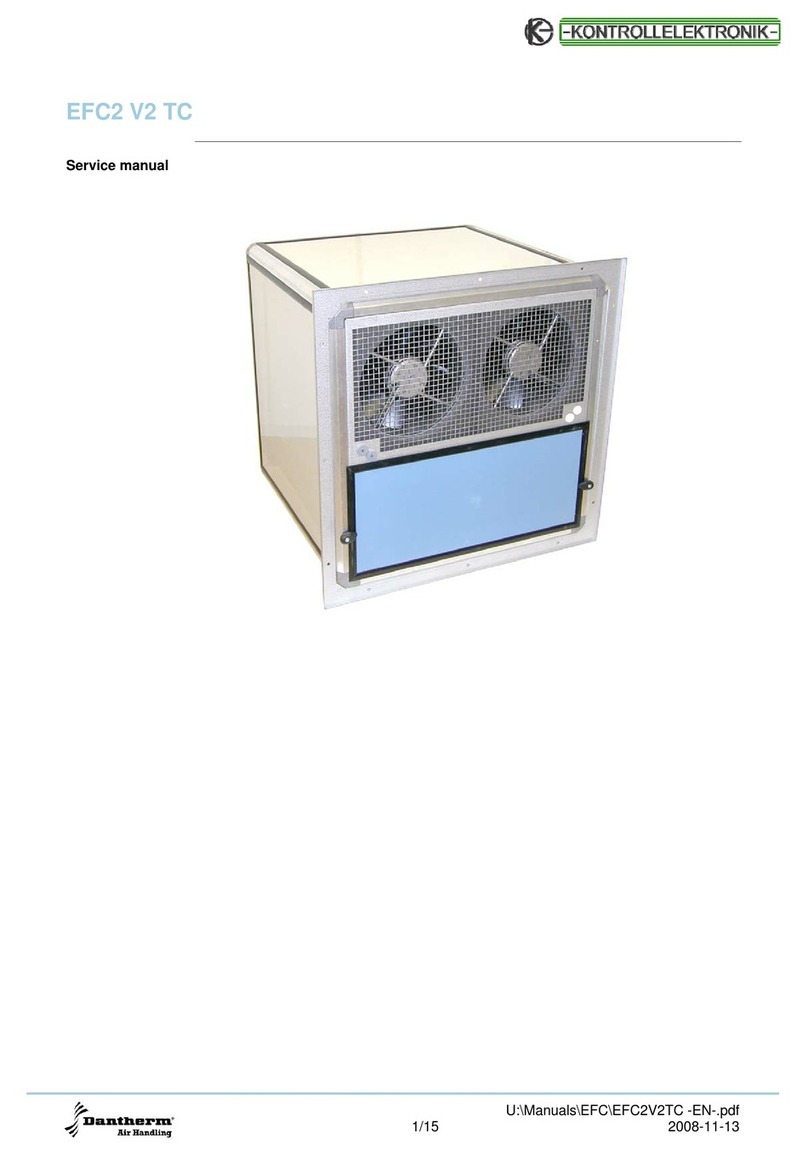
Dantherm KONTROLLELEKTRONIK EFC2 V2 TC User manual

Dantherm

Dantherm KONTROLLELEKTRONIK EFC2 V2 TC User manual

Dantherm TKS 60 User manual

Dantherm

Dantherm TKS 60 User manual

Dantherm HCV 500 User manual

Dantherm

Dantherm HCV 500 User manual

Dantherm DanX 2/4 User manual

Dantherm

Dantherm DanX 2/4 User manual

Dantherm cdp 75 User manual

Dantherm

Dantherm cdp 75 User manual

Dantherm HCV 3 User manual

Dantherm

Dantherm HCV 3 User manual

Dantherm HCV 3 Installation and maintenance instructions

Dantherm

Dantherm HCV 3 Installation and maintenance instructions

Dantherm VA-M40 MKII User manual

Dantherm

Dantherm VA-M40 MKII User manual

Dantherm WA 45 User manual

Dantherm

Dantherm WA 45 User manual

Dantherm BasX User manual

Dantherm

Dantherm BasX User manual

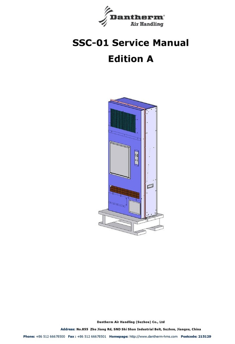
Dantherm SSC-01 User manual

Dantherm

Dantherm SSC-01 User manual

Popular Air Handler manuals by other brands
NuAire ESBH Series Installation and Maintenance

NuAire

NuAire ESBH Series Installation and Maintenance

Trane Technologies 23 Series Installer manual

Trane Technologies

Trane Technologies 23 Series Installer manual

Salda Veka INT 3000-15 L1 EKO Technical manual

Salda

Salda Veka INT 3000-15 L1 EKO Technical manual

RDZ CHR 200-FC Technical installation manual

RDZ

RDZ CHR 200-FC Technical installation manual

Unico M Series installation manual

Unico

Unico M Series installation manual

CIAT COMFORT LINE instruction manual

CIAT

CIAT COMFORT LINE instruction manual

Air Handlers Envirofresh Series Installation, operation & maintenance instructions

Air Handlers

Air Handlers Envirofresh Series Installation, operation & maintenance instructions

DSSA POWERMATE 16 manual

DSSA

DSSA POWERMATE 16 manual

Lennox SL280DFNV Series Unit information

Lennox

Lennox SL280DFNV Series Unit information

McQuay RoofPak RAH 047C Installation and maintenance manual

McQuay

McQuay RoofPak RAH 047C Installation and maintenance manual

Lennox B Series manual

Lennox

Lennox B Series manual

Ingersoll-Rand AC Series Installer's guide

Ingersoll-Rand

Ingersoll-Rand AC Series Installer's guide

EarthLinked AVS Series installation manual

EarthLinked

EarthLinked AVS Series installation manual

Carrier 39CCN Installation, Start-Up and Service Instructions

Carrier

Carrier 39CCN Installation, Start-Up and Service Instructions

Vents Micra 150 E user manual

Vents

Vents Micra 150 E user manual

Mitsubishi Electric PAC-TZ02-E Service manual

Mitsubishi Electric

Mitsubishi Electric PAC-TZ02-E Service manual

ClimateCraft DHII-007 Installation, operation and maintenance manual

ClimateCraft

ClimateCraft DHII-007 Installation, operation and maintenance manual

Airmark GBW Series installation guide

Airmark

Airmark GBW Series installation guide

manuals.online logo
manuals.online logoBrands
  • About & Mission
  • Contact us
  • Privacy Policy
  • Terms and Conditions

Copyright 2025 Manuals.Online. All Rights Reserved.