Dantherm MTS2 User manual

MTS2 Outdoor Solution
Service manual
EN
No. 039131 • rev. 1.0 • 06.06.2007

Der tages forbehold for trykfejl og ændringer
Dantherm can accept no responsibility for possible errors and changes
Irrtümer und Änderungen vorbehalten
Dantherm n’assume aucune responsabilité pour erreurs et modifications éventuelles

3
Introduction
Overview
This manual covers Dantherm Air Handling units with serial numbers equal or higher
than: 0609220899808
Serial number
WARNING It is the responsibility of the operator to read and understand this service manual
and other information provided, and to use the correct operating procedures.
Read the entire manual before the initial start-up of the installation of the MTS 2-
outdoor enclosure. It is important to know the correct operating procedures for the unit
and all safety precautions to prevent the possibility of property damage and/or personal
injury.
In case the MTS 2-outdoor enclosure is placed
indoor in a closed room, the ventilation capability of
the room should minimum be in accordance with the
battery standard and battery manufactures
recommendations.
This can be found on a label situated next to the
batteries (when installed).
The requirement is 0.19 m3/h.
When the cabinet is installed outdoor, no additional
ventilation is required with required degassing kit
installed (tube system from battery valve to exterior)
through retaining grommet. Always check if this tube
has not been damaged or removed.
Left bay of the enclosure above the power distribution panel offers a 19” rack system
with 6RU available for auxiliary equipment.
It is important that any active component in the rack, including those components that
will be installed later in addition to Dantherm’s deliverable, must have a self-protecting
mechanism, which switches off the component in case of an overheat situation.
Further it is important that the heat dissipation of equipment installed do not exceed
100 W or max. permitted ambient temperature will have to be de-rated.
This service manual covers the following main topics:
Table of contents
Topic See page
General information 5
Product- and functional description 7
MTS 2-outdoor enclosure 8
Power distribution panel 9
Heat exchanger 10
Set up and transport of the MTS 2-outdoor enclosure including the
MHX 35 heat exchanger 13
Service guide 17
039131 • 1.0 • 06.06.2007
Continued overleaf

4
General information, continued
Table of contents,
continued Topic See page
Preventive maintenance 18
Spare parts 19
How to replace the controller 20
How to replace the internal fan 21
How to replace the external fan 22
How to replace the heat exchanger 23
How to replace battery pack (backup power) 24
Fault finding 30
Service agreement 31
Technical information 32
Technical data, MTS 2-outdoor enclosure 33
Technical data, MHX 35 heat exchanger 34
MTS 2-outdoor enclosure – with power meter 36
MTS 2-outdoor enclosure – without power meter 37
Wiring diagram, MHX 35 heat exchanger 35
References for the wiring diagrams 39
Options 41
Mounting template 43

5
General information
Introduction This section gives the general information about this service manual and about the unit.
Manual, part numberPart number of this service manual is 039131.
Target group The target group for this service manual is the technicians who install, maintain, and
exchange parts on the unit.
Copyright Copying of this service manual, or part of it, is forbidden without prior written
permission from Dantherm Air Handling A/S.
Reservations Dantherm Air Handling A/S reserves the right to make changes and improvements to
the product and the service manual at any time without prior notice or obligation.
MTS2-outdoor
enclosure
Dantherm Air Handling A/S, Marienlystvej 65, DK-7800 Skive hereby declare that the
unit mentioned below:
MTS2 Outdoor solution, product no. 352890:
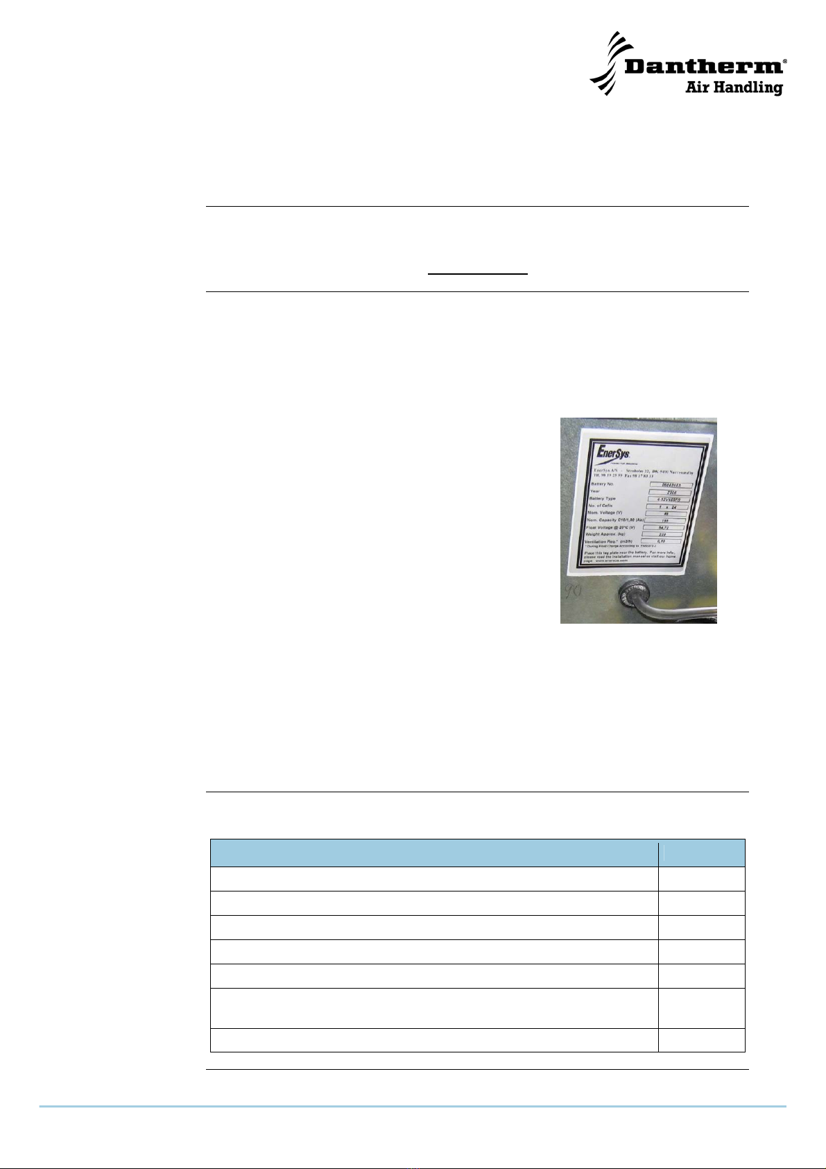
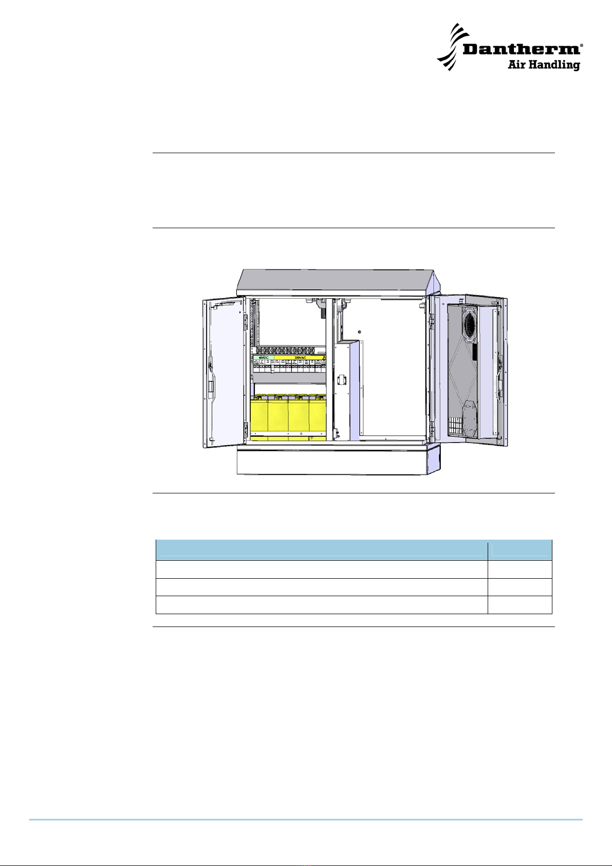
Description: MTS 2 outdoor solution is an outdoor cabinet or enclosure equipped for
accommodating and servicing an MTS2 base station. The cabinet has multiple
configurations ranging from a standard configuration with only a basic power
distribution panel (CE marked) and a heat-exchanger (CE marked) up to a full
integrated option list as defined in the service manual no 039131. Basis is equipped
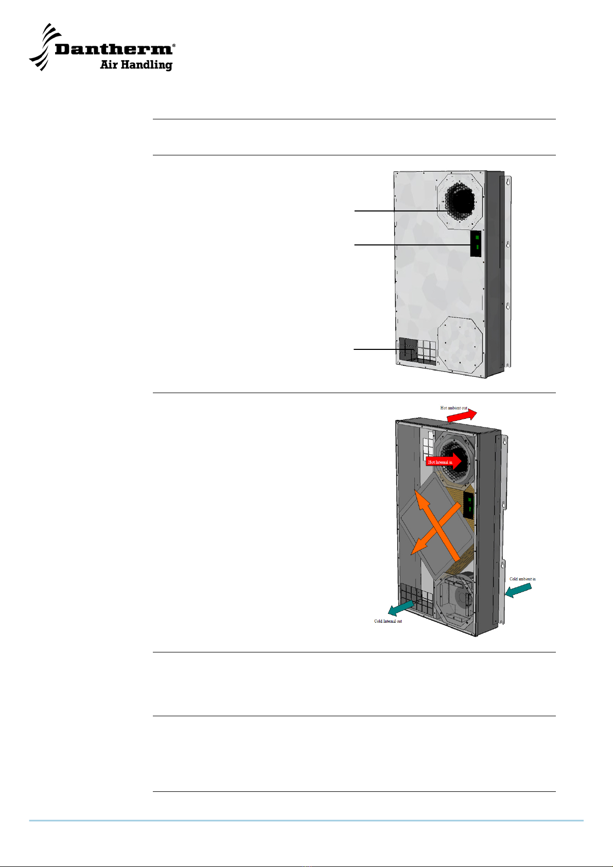
with a door mounted heat exchanger (352735)(std.)a battery installation capable of
retaining 3 different VRLA size batteries (optional)a power distribution panel (CE-
marked) and internal cables routing, cabin lights, battery charger, surge arrestors etc.
Items not listed in the service manual are not covered by this declaration.
- is in conformity with the following directives covering the provisions of the normative
European Council Directives:
98/37/EEC Directive on the safety of machines
73/23/EEC Low Voltage Directive
89/336/EEC EMC Directive
- and Manufactured in conformity with the following harmonized standard:
EN60529:2001 IP55* (Degree of protection provided by enclosures)
kat.2 verified
EN 292 Machine safety
EN 60 950-1:2001+A11
Installation safety
EN50272-2 Battery installation
EN 61 000-2 Immunity
EN 61 000-3 Emission
EN 61 000-4 Immunity
EN 55022_Class B*)
Emission
*) MTS 2 Outdoor Solutions" integrated with Motorola MTS
2 Base Station Type No. FR914B, FR917A or FT917B
complies to EN 55022_Class A Emission
ETSI EN 300 019-2-1 T 1.2
Storage: not temperature controlled storage locations
039131 • 1.0 • 06.06.2007
Continued overleaf

6
General information, continued
MTS2-outdoor
enclosure
, continued
ETSI EN 300 019-2-2 T 2.3
Transportation: public transportation
ETSI EN 300 019-2-4 T 4.1(or T4.1E)
In use: non-weather protected locations
ETSI ETS 300 753
Acoustic noise
and furthermore declares that it is not allowed to put the machinery into service until the
machinery into which it is to be incorporated or of which it is to be a component has
been found and declared to be in conformity with the provisions of above-mentioned
Directives and with national implementing legislation i.e. as a whole, including the
machinery referred to this declaration.
Skive, 28.02.2007
Recycling The MTS 2-outdoor enclosure is designed to last for many years. When the time
comes for the unit to be recycled, the unit should be recycled according to national
rules and procedures to protect the environment.

7
Product- and functional description
Overview
Introduction This section will give you a product and functional description of both the heat
exchanger unit and the MTS 2-outdoor enclosure.
A detailed description of the heat exchanger and the MTS 2-outdoor enclosure is to be
found on the following pages.
Illustration This illustrates the MTS 2-outdoor enclosure with the MHX 35 (heat exchanger unit)
hanging on the right door:
Options The MTS 2-outdoor enclosure might be equipped with one or more options. See a list
of options on page 41.
Topic See page
MTS 2-outdoor enclosure 8
Power distribution panel 9
Heat exchanger 10
039131 • 1.0 • 06.06.2007

8
MTS 2-outdoor enclosure
Introduction This section will give you a description of the MTS 2-outdoor enclosure and its
functionality.
The MTS 2-outdoor enclosure is designed to accommodate a Motorola MTS2 base
station, which is further described by Motorola. More information is available, please
contact Motorola.
Illustration This illustrates the MTS 2-outdoor enclosure:
e
f
d
c
g
hi
jkk
10
Part/function This table gives information about the single parts of the MTS 2-outdoor enclosure.
NB: All parts marked with a star (*) are options!
Part Function
cHeater*In case of cold external temperatures the heater
supplies heat for the enclosure
dSmoke detector* Detects smoke and sends an alarm signal
eGPS Surge arrestor* Protection of the GPS equipment against lightening or
excess voltage
fAntenna Surge arrestor* Protection of the receiver against lightening or excess
voltage
gExternal battery charger* Quick charger for the batteries
hPower meter* Shows AC power consumption
iHeat exchanger MHX 35 Cools down the electronics in the enclosure
jBatteries* Supplies backup time when power is unavailable
kData line Surge arrestor* Protection of the data line against lightening or
excess voltage
Manifold and three air
guides* Allows heat exchanger to take complete control of the
air distribution in MTS 2 base station.
Replaces standard fan trays
k
10

9
Power distribution panel
Introduction This section will give you a description of the power distribution panel and its
functionality:
Illustration These illustrations give an overview of the power
distribution panel which is build into the MTS 2-outdoor
enclosure.
Please see section “References for the wiring
diagrams”, page 39 for further references of the power
distribution panel.
Description The power distribution panel is for mounting to a 19” rack system and offers a 25
module DIN rail space, which is used for various circuit breakers rated to protect the
consumer and further surge protection as well as a HPFI relay to protect for potential
earth faults. Optional a power meter can be included.
The circuit breakers can also be used to activate or deactivate the user listed on the
overlay.
The panel has a clear split between DC and AC power. All DC power is in the left
section and AC powered section to the right. DC cables exiting the panel are routed
towards left.
039131 • 1.0 • 06.06.2007

10
Heat exchanger
Introduction This section will give you a description of the MHX 35 and its functionality:
Illustration This illustration gives an overview of the
heat exchanger which is build into the
MTS 2-outdoor enclosure:
Two separate air
flows The two air flows (internal/external) are
totally separated. The external air is only
used to cool down the internal air via the
heat exchanger. The air flows are never
mixed.
Internal air flow The warm internal air is sucked from the enclosure into the internal fan at the top of the
MHX 35 and let through the heat exchanger, where it is cooled down.
After the cooling in the heat exchanger, the air is let back into the enclosure.
External air flow The cold external air is sucked into the external fan at the bottom of the MHX 35 and let
through the heat exchanger, where it is cooling down the internal air.
After having passed through the heat exchanger, the air is let back to the external
environment at the top of the unit.
Continued overleaf
A
ir outle
t
Controller
A
ir inle
t

11
Heat exchanger, continued
Control system The MHX 35 heat exchanger is controlled
via a controller that controls the speed of
the fans.
The key features of the controller are:
•Onboard temperature sensor (NTC
type)
•Microproccesor based control in
accordance with preselected strategy
•Minor and major alarm output
•Polarity protection
•Input voltage ÷ 40 V DC to -60 V DC
•Power consumption 80 W
Part Function
RS 232 To be used for factory testing or to get further information from
the controller
Alarm LED Gives signal about alarms:
•Flashing = minor alarm (high temperature)
•Constant = major alarm (fan or sensor failure)
Both alarms can be monitored (potential free contact) on the
power/alarm plug.
See more about fault finding in section “Service guide”, page 17
Sub-D 9 pin, male Power and alarm plug
Pin designation:
1 N/C
2 + 48 V DC
3 + 48 V DC
4 Minor alarm +
5 Major alarm +
6 0 V DC
7 0 V DC
8 Minor alarm ÷
9 Major alarm ÷
Control strategy This shows the control strategy for the controller:
See the table on the next page for an explanation of the values.
039131 • 1.0 • 06.06.2007
Continued overleaf

12
Heat exchanger, continued
Values This table shows the set points/control strategy for the MHX 35 heat exchanger.
All listed temperatures are return air temperatures (from the enclosure to the heat
exchanger). Fan speeds are detected and controlled from speed signals from the fans.
Reduction Designation Value
IR1 Minimum internal fan speed 1400 RPM
IR2 Maximum internal fan speed 2800 RPM
IT- Cut off temperature, internal fan ÷ 10 °C
IT0 Cut in temperature, internal fan ÷ 5 °C
IT1 Ramp up temperature set point, internal fan 40 °C
IT2 Maximum RPM temperature set point, internal
fan 50 °C
ER1 Minimum external fan speed 1300 RPM
ER2 Maximum external fan speed 2600 RPM
ET- Cut off temperature, external fan 25 °C
ET0 Cut in temperature, external fan 30 °C
ET1 Ramp up temperature set point, external fan 45 °C
ET2 Maximum RPM temperature set point, external
fan 50 °C

13
Set up and transport of the MTS 2-outdoor enclosure including
the MHX 35 heat exchanger
Introduction This section provides information required for the unwrapping of the unit, mounting it
and making it ready for use
Transport The MTS 2-outdoor enclosure including options and MTS2 is designed to withstand
public transport.
Necessary tools The following tools are needed for the installation:
•27 mm wrench
•5 mm umbracho
•10 and 13 mm socket wrench
•Torx 30 screw driver
•Torx 25 screw driver
•Riveting tool for 4mm rivets
Electrical
connection A PG21 cable gland is located at the middle of the bottom and is to be used as main
power cable entry. The power cable needs to be attached to the main circuit breaker,
with N and L (phase) a ground stud (M6) is next to this serving as main ground.
The installation must be done by authorized personal only.
The main circuit breaker is rated 25 A.
Stacking Do not stack the enclosures!
Procedure Follow these steps to unwrap the enclosure and make it ready for use:
Step Action
1 Remove the wrap and the straps
Frontal view of cabinet
2 Prepare the mounting site according to the mounting template in appendix B,
page 43
3 Unscrew the 6 mm umbracho screw on
one of the bottom side cover plate and
dismount it
Cabinet at left bottom corner towards the backside
039131 • 1.0 • 06.06.2007
Continued overleaf

14
Set up and transport of the MTS 2-outdoor enclosure including
the MHX 35 heat exchanger, continued
Procedure, continued Step Action
4 Unscrew the 8 screws on the inner cover
plate and dismount it
The unit is now ready to be lifted up
Picture showing low leftside of cabinet
5 Lift the unit with a fork lift truck as shown
(in the lifting channel)
Be very careful when lifting and
secure the enclosure when working
under it (use supports)
Picture taken from the back and right side of the
enclosure
6 Lead the power cable through the PG
cable gland while the enclosure is about
to be lifted into place.
Data lines: E1, X21 and remote GPS
cable entry must be let through the
through the PG cable glands on the front
of the unit
The PG cable glands is placed on the
middle of the bottom
Upper picture taken from underneath the
enclosure center from left to right
Lower picture taken from underneath the
enclosure from left to right
Continued overleaf

15
Set up and transport of the MTS 2-outdoor enclosure including
the MHX 35 heat exchanger, continued
039131 • 1.0 • 06.06.2007
Procedure, continued Step Action
7 Unscrew the 6 torx screws on the sheet
with the PC plug.
Turn the sheet aside and the PG cable
glands for the power cable is visible from
the inside
NB: Installation must only be carried
out by authorized personnel
Picture taken through an open right door
8 Proceed with step 8 if the enclosure needs to be attached with bolts
otherwise proceed with step 9
9 Unscrew the two 8 mm screws on both
side cover plates and dismount the two
plates
This gives access to the fixing points
Lower corner of enclosure
10 Lower the enclosure to its right position (use the mounting template, page
43) while keeping the cables tight, so they do not get squeezed
11 Attach the enclosure with bolts by the fixing points shown on the mounting
template, page 43 (Dantherm Air Handling A/S recommendation)
12 Tighten all PG cable glands
13 Lead the power cable through the rubber
grommet and connect it to the AC input
on the switchboard according to the
wiring diagram
Picture taken trough open right door showing
cable entry
Continued overleaf

16
Set up and transport of the MTS 2-outdoor enclosure including
the MHX 35 heat exchanger, continued
Procedure, continued Step Action
14 Make sure all power has been
switched off and secured.
(authorized personal only).
Remove the cover of the power
distribution panel by unscrewing the 4
torx T25 screws and connect the
incoming power cord as illustrated to the
right.
Make sure the M6 marked ground
connection is tightened and secured as
illustrated
Upper picture showing power distribution board
with cover removed.
Lower picture close up at power entry point to the
power distribution board
15 Connect the buried exterior bare conductor forming a ring around the
enclosure according to K56 by ITU-T by using the M8 nut located at the
bottom of the enclosure in each corner
16 Remount all cover plates and the MTS 2-outdoor enclosure is ready for use
17 Attach the blinding plates (one on each
side) by pulling the enclosed rivets with
an appropriate tool, when the endplates
have been remounted as shown on the
upper picture.
The blinding plates are for additional
protection towards entry to bottom
section
Picture showing the attached blind in position

17
039131 • 1.0 • 06.06.2007
Service guide
Overview
CAUTION Always disconnect the power cable from the unit before doing any service!
Content This chapter covers the following topics:
Topic See page
Preventive maintenance 18
Spare parts 19
How to replace the controller 20
How to replace the internal fan 21
How to replace the external fan 22
How to replace the heat exchanger 23
How to replace battery pack (backup power) 24
Fault finding 30
Service agreement 31

18
Preventive maintenance
Introduction Proper maintenance of the unit is necessary in order to achieve trouble-free operation.
This section contains description of the recommended maintenance.
Contractual serviceDantherm Air Handling A/S provides contractual service agreements covering
preventive and/or corrective maintenance – see section ”Service agreement”, page 31
for further information.
CAUTION Always disconnect the power from the MTS 2-outdoor enclosure before doing any
preventive maintenance!
Preventive main-
tenance, MTS 2-
outdoor enclosure
Please follow this procedure to carry out the preventive maintenance, which should not
exceed 6 months:
Step Action
1 Check if door gaskets are damaged – exchange if necessary
2 Check and clean if necessary the door louvres
Preventive main-
tenance, power
distribution panel
Dantherm Air Handling recommends to switch all circuit breakers off an back on (if in
use) once a year. Make sure that the base station is not unintentionally affected by this.
The HPFI protection relay (F1.32) has a test button that needs periodically activation.
Recommended every 6 months:
Further the F1.34 transient protection can be damaged by a strike of lightning or similar
in the power supply. It has a replaceable cartridge that needs replacement when the
indicator in front turns red.
Preventive main-
tenance, MHX 35 Please follow this procedure to carry out the preventive maintenance, which should not
exceed 6 months:
Step Action
1 Clean the fans, either vacuum clean or use compressed air with caution
2 Clean the cross heat exchanger with compressed air
3 Check the fans and the fan blades for cracks – exchange if necessary
4 Check the fans for abnormal noise – exchange if necessary
Preventive main-
tenance, batteries Please follow this procedure to carry out the preventive maintenance, which should not
exceed 6 months. Batteries are optional equipment.
Step Action
1 Check that the battery ventilation hoses are intact and in place. If damaged
order a replacement degassing kit

19
Spare parts
MHX 35 This illustrates the spare parts for the MHX 35 heat exchanger:
Fig. 1
External fan
040278
M
HX35 as sparepar
t
040279
Controller
040275
Internal fan
040274
039131 • 1.0 • 06.06.2007

20
How to replace the controller
Introduction The controller is located on the front of the heat exchanger.
When to replace it The controller must only be replaced when it is defective.
Before you start Before you start to replace the controller, make sure that you have the following ready:
•A torx 25 screwdriver
•A new controller
Drawing This drawing shows where the controller is
placed:
Procedure Follow these steps to replace the controller:
Step Action
1 Switch off all power to the MTS 2-outdoor enclosure and to the MHX 35heat
exchanger
2 Open the MTS 2-outdoor enclosure to get access to the MHX 35 heat
exchanger
3 Remove the 4 torx screws to remove the controller
4 Pull out carefully the controller and disconnect the two cable plugs
5 Fit the two plugs to the new controller and tighten it with the 4 screws
6 Switch on the power again
Controller
Table of contents
Popular Outdoor Storage manuals by other brands

Patiowell
Patiowell T-PS22-0110-BK Assembly instructions

Duratuf
Duratuf GARRISON PS62 Assembly instructions

Lifetime
Lifetime 60001 Assembly instructions

dellonda
dellonda DG114 manual

Arrow Storage Products
Arrow Storage Products CG1012 Owner's manual & assembly instructions

Asgard
Asgard ADDITION quick start guide

Palram
Palram Sky Light 8x8 instructions

ABSCO SHEDS
ABSCO SHEDS 3045UTK Assembly & instruction manual

Arrow Storage Products
Arrow Storage Products Select SCG88CC Owner's manual & assembly guide

Scotts
Scotts STTPS43 Owner's manual & assembly guide

eazished
eazished EZ-16242 Assembly instructions

Keter
Keter CORTINA 77 user manual