Data Technology 5280CRA User manual

•
DATA
TECHNOLOGY
I c a R P a
RAT
a N
DATA TECHNOLOGY
CORPORATION
INSTALLATION GUIDE
FOR THE
5280CRA
PC/AT
HARD DISK & FLOPPY DISK CONTROLLER
2551
Walsh
Avenue
Santa
Clara,
CA
95051
U.s.A.
Telephone
(408)
727-8899
DATA
TECHNOLOGY
CORPORATION
Printed
in
Taiwan
July
'87
TWX
474-5044
DTCSC

* * *
WARNING
* * *
The
equipment
generates
and
uses
radio
frequency
energy
and
if
not
installed
and
used
properly,
that
is,
in
strict
accordance
with
the
manufacturer's
instructions,
may
cause
interference
to
radio
and
television
reception.
It
has
been
type
tested
and
found
to
comply
with
the
limits
for
a
Class
B
computing
device
in
accordance
with
the
specifications
in
subpart
,
of
Part
15
of
FCC
Rules,
which
are
designed
to
provide
reasonable
protection
against
such
interference
in a
residential
installation.
However,
there
is
no
guarantee
that
interference
will
not
occur
in
a
particular
installation.
If
this
equipment
does
cause
interference
to
radio
or
television
reception,
which
can
be
determined
by
turning
the
equipment
off
and
on,
the
user
is
encouraged
to
try
to
correct
the
interference
by
one
or
more
of
the
following
measures:
*
Reorient
the
receiving
antenna.
*
Relocate
the
computer
with
respect
to
the
receiver.
*
Move
the
computer
away
from
the
receiver.
*
Plug
the
computer
into
a
different
outlet
so
that
computer
and
receiver
are
on
different
branch
circuits.
*
If
necessary,
the
user
should
consult
the
dealer
or
an
experienced
radio/television
technician
foy
additional
suggestions.
The
user
may
find
the
following
booklet
prepared
by
the
Federal
Communications
Commission
helpful:
"How
to
Identify
and
Resolve
Radio-TV
Interference
Problems".
This
booklet
is
available
from
the
u.s.
Government
Printing
Office,
Washington,
DC
20402.
Stock
No.
004-000-00345-4

TABLE
OF
CONTENTS
1.0
Introduction
...........................................................................................1
2.
Equipment
needed
to
do
installation
..............................................1
3.0
Jumper
settings
....................................................................................1
3.1
Reserved
jumper
...........................................................................2
3.2
Primary/secondary
port
address
..............................................2
3.3
Initial
data
rate
control
jumper.
................................................2
3.4
Firmware/hardware
drive
select
jumper
.................................2
3.5
Floppy
precompensation
control...
............................................2
4.0
Installation
and
formatting
hard
disk
...........................................3
4.1
Floppy
drives
.................................................................................3
4.2
Hard
drives
.....................................................................................3
4.3
Formatting
the
drive
....................................................................3
DTC
Part
Number
09·00343·1
Revision
A
29·JAN·1987
This
installation
gUide
and
the
associated
software·
firmware
are
copyrighted
(c)
1983,
1984
DTC
..
1.0
INTRODUCTION
The
DTC
5280CRA
controller
is
designed
to
function
as
a
combination
hard
drive
and
floppy
drive
controller
in
"AT"
type
systems
that
do
not
have
the
floppy
drive
function
on
the
motherboard
or
on
another
board
in
the
system.
The
5280CRA
is
able
to
control
two
5.25"
or
3.5"
Winchester
or
removable
cartridge
hard
disks
and
two
floppy
disk
drives.
2.0
EQUIPMENT NEEDED TO DO INSTALLATION
The
following
equipment
is
needed
to
install
the
DTC
5280CRA
controller:
For
one
hard
disk
and
one
or
two
floppies
ea
20
pin
data
cable
ea
34
pin
cable
ea
34
pin
daisy
chain
calbe
For
two
hard
disks
and
one
or
two
floppies
2
ea
20
pin
data
cables
2
ea
34
pin
daisy
chain
cables
Software:
IBM
Advanced
Diagnostics
Program
diskette
or
a
similar
formatting
utility.
3.0
JUMPER SETTINGS
Refer
to
diagram
3.1
for
jumper
locations.
LED
CONNEcroR
lUl'
lS
DIAGRAM 3.1 .
5280CRA
JUMPER LOCATIONS
-1-

3.0
JUMPER SETfINGS
(cont.)
3.1
RESERVED JUMPER (W1)
Jumper
W1
is
for
internal
use
only
and
must
be
open
(removed)
for
the
controller
to
operate
properly.
3.2
PRIMARY/SECONDARY PORT ADDRESS JUMPER
(W2
&
W3)
The
W2
and
W3
jumpers
are
for
the
floppy
and
hard
drive
port
addresses.
They
should
be
set
as
follows:
W2
and
W3
and
installed
=
Primary
port
address
(1
FO
to
1F7,
3F2
to
3F7)
W2
and
W3
installied
=
Secondary
port
address
(170
to
177,
372
to
377)
3.3
INITIAL DATA RATE CONTROL JUMPER (W4)
Jumper
W4
controls
the
power·up
data
transfer
rate
for
floppy
drive.
W4
installed
=
250KHz
W4
not
installed
=
500KHz
(default)
3.4
FIRMWARE/HARDWARE DRIVE SELECT JUMPER
(W5&W6)
Jumpers
W5
and
W6
determines
firmware
select
mode
or
hardware
select
mode
is
enabled.
Hardware
select
mode
(as
shipped):
W5
installed
and
W6
2·3
installed,
5·6
installed.
Firmware
select
mode:
W5
not
installed
and
W6
1·2
installed,
4-5
installed.
3.5
FLOPPY PRECOMPENSATION CONTROL JUMPER
(W7)
Two
modes
of
precompensation
for
the
floppy
drive
are
supported
on
this
controller.
W7
installed
=
precompensation
at
125ns
W7
removed
=
precompensation
is
scaled
by
the
data
rate
floppy
drive
is
running
on
(125ns
for
500KHz,
208ns
for
300KHz,
and
250ns
for
250KHz).
W7
is
not
installed
at
the
factory.
4.0
INSTALLATION AND FORMATTING
OF
THE
HARD DISK
4.1 FLOPPY DRIVES
Installation
of
the
floppy
drives
reqUires
a
34
pin
twisted
type
cable.
Both
drives
should
be
set
for
drive
select
2
(this
assumes
drive
selects
are
numbered
1
,2,3,
4).
Install
the
header
pin
end
of
the
cable
onto
J1
of
the
controller
with
the
colored
edge
of
the
cable
aligned
with
pin
1
as
shown
in
Diagram
3.1.
The
connector
at
the
other
end
of
the
cable
should
be
connected
to
drive
A:
and
the
middle
connector
to
drive
B:,
both
with
pin
1
aligned
with
pin
1
of
the
drive
connector.
Only
drive
A:
should
have
the
terminator
installed.
4.2
HARD DRIVES
4.2.1
Single-Drive
System
4.2.2Cable
connections
Install
the
34
pin
connector
onto
J2
of
the
controller
with
the
colored
edge
of
the
ribbon
cable
aligned
to
pin
1
as
shown
in
diagram
3.1.
Install
the
20
pin
connector
onto
J3
of
the
controller
with
the
colored
edge
of
the
ribbon
cable
aligned
to
pin
1
as
shown
in
diagram
3.1.
Install
the
20
and
34
pin
connectors
to
the
disk
drive
with
the
colored
edge
of
the
ribbon
cable
aligned
with
pin
1
of
the
drive
edge
connectors.
Be
sure
the
terminator
is
installed
and
the
drive
select
is
set
for
drive
1.
(This
assumes
the
drive
selects
are
numbered
1
to
4)
,
4.3
FORMATTING THE DRIVE
l
4.3.1
To
initialize
the
drive,
put
the
IBM
Diagnostics
diskette
into
drive
A:
and
turn
on
the
power.
After
the
system
goes
through
system
test,
the
diagnostics
menu
will
appear
on
the
screen.
(Bold
printing
is
what
is
shown
on
the
screen.)
This
program
provides
functions
for
preparation
of
a
new
fixed
disk
drive,
including
selecting
drive
type,
formatting
(low level),
verification
and
defect
mapping
of
the
drive.
All
are
done
in
a
menu
driven
fashion.
-2-
-3-

4.3
FORMAITING THE DRIVE
(cont.)
4.3.2
The
screen
will
show
the
following
select
options:
SELECT
AN OPTION
o .
System
checkout
1 .
Format
diskette
2 .
Copy
diskette
3 .
Prepare
system
for
moving
4·
Setup
9 .
End
diagnostics
Select
the
action
desired
?
4.3.3
At
the
"?"
prompt
type:
4 <
Enter>.
One
the
next
screen,
follow
the
menu
to
set
up
all
other
options
and
the
fixed
disk
drive
type.
4.3.4
After
completing
the
system
setup,
the
system
will
re·boot,
and
the
above
select
options
menu
will
appear
again.
At
the
"?"
prompt
type:
0 <
Enter
>-
to
run
system
checkout.
4.3.5
The
screen
will
show
a
list
of
all
the
installed
devices
and
the
following
message:
Is
the
list
correct
(YIN)
(If
the
list
is
not
correct,
enter
"N"
to
run
setup
again.)
4.3.6
If
the
information
Is
correct
type:
"Y".
The
following
screen
will
appear:
System
Checkout
O-run
tests
one
time
1
-run
tests
multiple
times
2
-log
utilities
9-end
system
checkout
Select
the
action
deSired
?
4.3.7
At
the
"?"
prompt
type:
0 <
Enter>.
The
screen
will
now
show
the
list
of
the
installed
devices
and
the
following
message:
-4-
4.3.7
(cont.)
1-
system
board
2-xxx
KB
Memory
3-Keyboard
6-1
(2)
Diskette
drive(s)
and
adapter
9
-Serial/parallel
adapter
17-1
Fixed
disk
drivels)
and
adapter
Select
option
number(s)
to
test
or
press
"enter"
to
select
all
options?
4.3.8
At
the
"?"
prompt
type:
17 <
Enter>.
The
following
screen
will
appear:
FIXED
DISK
DIAGNOSTIC MENU
1-
Write,
read,
compare
(in
test
cylinder)
2-Seek
test
3-Head
select
4-
Error
detection
&
correction
5-Run
all
test
6-
Read
verify
7-Format
menu
9-
Return
to
control
program
For
option
9
type
"9"
and
press
"enter"
For
other
options
type
the
option
number,
drive
ID
(1,
C)
and
press
"enter"
4.3.9
At
tbe
"?"
prompt
type:
7,C
<Enter>.
The
screen
will
show
the
following:
FORMAT SELECTION MENU
1-
Conditional
format
2-
Unconditional
format
3-Surface
analysis
4-Change
interleave
9-Return
to
fixed
disk
menu
For
option
9
type
"9"
and
press
"enter"
For
other
options
type
the
option
number,
drive
ID
(1,
C)
and
press
"enter"
4.3.10
At
the
"?"
prompt
type:
(1
or
2)
<Enter>
1-for
conditional
format*
2-for
unconditional
format*
-5-

4.3.10
(cont.)
The
following
message
will
appear:
****
WARNING
****
ALL
DATA ON THE
FIXED
DISK
WILL
BE
DESTROYED
DO
YOU
WANT
TO
CONTINUE?
ENTER
(YIN)
*Note:
Unconditional
format
-
runs
low
level
format
only
Conditional
format
-
runs
surface
analysis,
low
level
format,
and
verification.
4.3.11
Enter
"Y"
to
proceed
with
the
format.
After
the
format
is
done,
exit
the
diagnostics
program
and
proceed
with
the
FDISK
and
FORMAT
programs
as
described
in
the
DOS
manual
to
complete
the
hard
disk
preparation.
Table of contents
Other Data Technology Controllers manuals
Popular Controllers manuals by other brands
ETI
ETI PFC 12 RS User and service manual
Honeywell
Honeywell T775 Series Application guide and cross reference
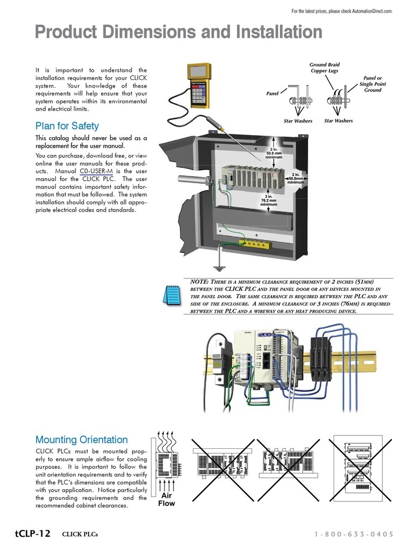
AutomationDirect
AutomationDirect CLICK Product Dimensions and Installation
AMX
AMX UPC20 Plus quick start guide
OutBack Power
OutBack Power FLEXmax 60 owner's manual

NACO
NACO XBOX DAIJA ARCADE STICK Start guide
