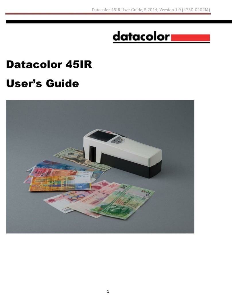
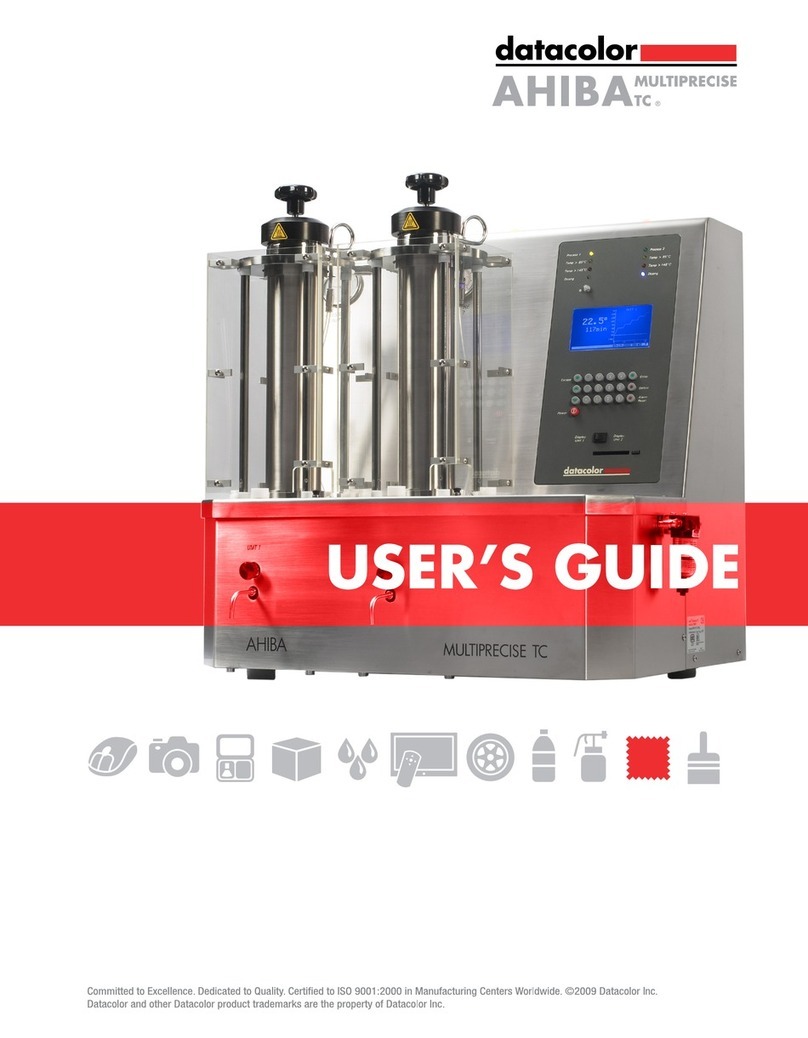
Datacolor CONDITIONER User manual

Operation Manual
Datacolor CONDITIONER™
Sample conditioning cabinet
with RP1 controller
with and without lighting option
Rev 3.0
7th August 2007
DCCOPMN_RP1_03

Datacolor Conditioner Operation Manual / DCCOPMN_RP1 / Rev 3.0 / 7th August 07 page 2/51
CONTENTS
1. SAFETY..................................................................................................................4
1.1 Legal considerations ...........................................................................................................................4
1.2 Structure of the safety instructions......................................................................................................4
1.3 General safety instructions on installing and operating ......................................................................6
1.4 Intended use .......................................................................................................................................8
2. UNIT DESCRIPTION..............................................................................................8
2.1 Datacolor CONDITIONER™ with lighting unit....................................................................................9
2.2 Datacolor CONDITIONER™ without lighting unit...............................................................................9
2.3 Unit overview.....................................................................................................................................10
2.4 Instrument box ..................................................................................................................................12
2.5 Lateral control panel .........................................................................................................................14
3. SCOPE OF DELIVERY, TRANSPORTATION, STORAGE AND INSTALLATION15
3.1 Unpacking, and checking equipment and scope of delivery.............................................................15
3.2 Advice for safe lifting and transportation...........................................................................................15
3.3 Storage..............................................................................................................................................15
3.4 Location of installation and ambient conditions ................................................................................16
4. INSTALLATION AND CONNECTIONS................................................................17
4.1 Mains water supply (connection to a water tap) ...............................................................................18
4.2 Hose burst protection device with reflux protection device (option) .................................................20
4.3 Water supply pumped from a water tank (option available when ordering the system cannot be
retrofitted)..........................................................................................................................................21
4.4 Waste water connection....................................................................................................................23
4.5 Water and connection sets supplied with Datacolor Conditioner systems.......................................24
4.6 Electrical connection .........................................................................................................................27
5. START UP AND SWITCH ON THE UNIT ............................................................28
6. SETTING UP THE CONTROLLER RP1...............................................................29
6.1 Locking of the operating parameter set up .......................................................................................31
7. TEMPERATURE SAFETY DEVICES...................................................................32
7.1 Electric safety controller (temperature safety device class 3.1) .......................................................32
7.2 Over temperature protective device (temperature limiter class 1)....................................................33
7.3 Over temperature protective device (temperature fuse class 1) ......................................................33
8. NOTIFYING AND ALARM FUNCTIONS..............................................................34
8.1 Alarm messages ...............................................................................................................................34
8.2 Error messages.................................................................................................................................39
9. HUMIDIFYING AND DEHUMIDIFYING SYSTEM ................................................40
9.1 Humidifying and dehumidifying system of CONDITIONERTM with lighting unit................................40
9.2 Humidifying and dehumidifying system of CONDITIONERTM without lighting unit...........................41
10. LIGHTING UNIT OF THE CONDITIONER™........................................................42
10.1 Counter of operating hours ...............................................................................................................42
11. MAINTENANCE, CLEANING, AND SERVICE ....................................................43
11.1 Maintenance intervals, service..........................................................................................................43
11.2 Replacement of the fluorescent tubes ..............................................................................................43
11.3 Cleaning and decontamination .........................................................................................................44

Datacolor Conditioner Operation Manual / DCCOPMN_RP1 / Rev 3.0 / 7th August 07 page 3 of 51
12. DISPOSAL............................................................................................................45
12.1 Disposal of the transport packing .....................................................................................................45
12.2 Decommissioning..............................................................................................................................45
12.3 Disposal of the unit in the member states of the EC.........................................................................46
12.4 Disposal of the unit in non-member states of the EC .......................................................................47
13. TECHNICAL DESCRIPTION................................................................................48
13.1 Factory calibration and adjustment...................................................................................................48
13.2 Over current protection .....................................................................................................................48
13.3 Residual current operated device .....................................................................................................48
13.4 Definition of usable space.................................................................................................................48
13.5 Technical Data Datacolor CONDITIONER™....................................................................................49
13.6 Equipment .........................................................................................................................................50
13.7 Dimensions Datacolor CONDITIONERTM .........................................................................................51

Datacolor Conditioner Operation Manual / DCCOPMN_RP1 / Rev 3.0 / 7th August 07 page 4 of 51
Dear Customer,
For correct and safe operation of the Datacolor CONDITIONER™ sample conditioning cabinet, it is
necessary to read this operation manual completely and carefully, and observe all given instructions.
1. Safety
This operation manual is part of the scope of delivery. Always keep it at hand.
To avoid injuries and damage observe the safety instructions of the operation manual.
WARNING
Failure to observe the safety instructions may lead to serious injuries and unit
damage.
¾Observe the safety instructions in this operation manual.
¾Carefully read the complete operating instructions of the Datacolor CONDITIONER™
sample conditioning cabinet.
1.1 Legal considerations
This operation manual contains information necessary for the intended use, correct installation, start-up
and operation, and for the maintenance of the unit.
Understanding and observing the instructions in this operation manual are prerequisites for hazard-free
use and safety during operation and maintenance.
This operation manual cannot cover all conceivable applications. If you would like additional information,
or if special problems arise that you feel are not sufficiently addressed in this manual, please ask your
Datacolor representative.
1.2 Structure of the safety instructions
In this operation manual, the following harmonized denominations and symbols indicate dangerous
situations, following the harmonization of ISO 3864-2 and ANSI Z535.4.
1.2.1 Signal word panel
Depending on seriousness and probability of the consequences, dangers are identified with a signal
word, the corresponding safety color, and if appropriate, the safety alert symbol.
DANGER
Indicates an imminently hazardous situation that, if not avoided, will result in death or serious
(irreversible) injury.
WARNING
Indicates a potentially hazardous situation which, if not avoided, could result in death or serious
(irreversible) injury

Datacolor Conditioner Operation Manual / DCCOPMN_RP1 / Rev 3.0 / 7th August 07 page 5 of 51
CAUTION
Indicates a potentially hazardous situation which, if not avoided, may result in moderate or minor
(reversible) injury
CAUTION
Indicates a potentially hazardous situation which, if not avoided, may result in damage of the product
and/or its functions or of a property in its ambiance.
1.2.2 Safety alert symbol
Use of the safety alert symbol indicates risk of injury.
Observe all measures that are marked with the safety alert symbol in order to avoid death or
injury.
1.2.3 Pictograms
Warning signs
Electrical hazard
Hot surface
Explosive substances
Tip over hazard
High humidity
Pollution Hazard
Harmful substances
Biohazard
Mandatory action signs
Mandatory regulation
Read operating
instructions
Pull the power plug
Lift with several persons
Environment protection
Prohibition signs
Do NOT touch
Do NOT spray with
water
Do NOT climb
Do not connect to
pressurized main water.
Information to be observed in order to ensure optimum function of the product.

Datacolor Conditioner Operation Manual / DCCOPMN_RP1 / Rev 3.0 / 7th August 07 page 6 of 51
1.2.4 Word message panel structure
Type / cause of hazard.
Possible consequences.
∅Instruction how to avoid the hazard: prohibition
¾Instruction how to avoid the hazard: mandatory action
Observe the other notes and information not specially emphasized in the same way, in order to avoid
disturbances which could result in direct or indirect injuries or property damage.
1.3 General safety instructions on installing and operating
With regard to operating the Datacolor CONDITIONER™ sample conditioning cabinet and to the
installation location, please observe the local national safety regulations that apply for laboratories or in a
room similar to a laboratory.
When the CONDITIONER™ is installed, operated, cleaned, decontaminated, adjusted or set up
incorrectly, there is a risk of malfunction which could cause harm to human beings and material damage
to the equipment and samples.
Therefore the CONDITIONER™ should only be installed, operated, cleaned, decontaminated, adjusted
and set up by suitably qualified persons.
•Persons qualified to install, operate, clean, and decontaminate the CONDITIONER™ include
everyone who has carefully read the user manual.
•Persons qualified to repair and adjust the CONDITIONER™ only include electricians and service
engineers authorized by the Datacolor, who have undergone appropriate electrical training and who
have carefully read the CONDITIONER™ service and user manual.
To operate the unit, use only original Datacolor accessories, or accessories of third-party suppliers
authorized by Datacolor
CAUTION
Danger of overheating.
Damage of the unit.
∅Do NOT install the unit in unventilated recesses.
¾Ensure sufficient ventilation for carrying-off the heat.
DANGER
Explosion hazard.
Danger of life.
∅Do NOT operate the unit in potentially explosive areas.
∅NO explosive dust or air-solvent mixture in the ambiance.
The Datacolor CONDITIONER™ provides no protection against explosions. Never install or operate the
Datacolor CONDITIONER™ in a location where explosive gases, powder or solvent-air mixtures could
penetrate.

Datacolor Conditioner Operation Manual / DCCOPMN_RP1 / Rev 3.0 / 7th August 07 page 7 of 51
DANGER
Explosion hazard.
Danger of life.
∅Do NOT introduce any substance combustible or explosive at working temperature into
the sample conditioning cabinet.
∅NO explosive dust or air-solvent mixture in the inner chamber.
Any solvent contained in the charging material must not be explosive or inflammable. I.e., irrespective of
the solvent concentration in the steam room, NO explosive mixture with air will form. The temperature
inside the chamber must lie below the flash point or below the sublimation point of the charging material.
Keep informed about the physical and chemical properties of the charging material, as well as the
contained moisture constituent and its behaviour under addition of heat energy and humidity.
Keep informed about any potential health risks caused by the charging material, the contained moisture
constituent or by reaction products that may arise during the temperature process. Take adequate
measures to exclude such risks prior to putting the sample conditioning cabinet into operation.
DANGER
Electrical hazard.
Danger of life.
∅The unit must NOT become wet during operation or maintenance.
The sample conditioning cabinets have been produced in accordance to the VDE regulations and were
routinely tested in accordance to VDE 0411.
CAUTION
The glass doors and the inner chamber will heat up to 50°C during operation.
∅Do NOT touch the glass doors, the inner surfaces and the charging material during
operation.
WARNING
Tip over hazard.
Danger of injury.
Damage of the unit and the charging material.
Housing cover breakaway.
∅Do NOT climb the lower housing cover.
∅Do NOT charge the lower housing cover with heavy objects while the unit door is open.

Datacolor Conditioner Operation Manual / DCCOPMN_RP1 / Rev 3.0 / 7th August 07 page 8 of 51
1.4 Intended use
Datacolor CONDITIONER™ sample conditioning cabinets are designed for exact conditioning of
harmless materials. A mixture of any component of the charging material mixed with air must NOT be
explosive. The operating temperature must lie below the flash point or below the sublimation point of the
charging material.
Respecting the instructions in this operation manual and conducting regular maintenance
work (chap. 11) is part of the intended use.
2. Unit description
Datacolor CONDITIONER™ sample conditioning cabinet with controller RP1 is available in two different
types:
•with lighting unit
•without lighting unit
Datacolor CONDITIONER™ is designed for exact conditioning of harmless materials such as paper,
textiles, plastics, building materials, to condition the samples at fixed temperature and humidity, so as
ensure no change in color of the samples occurs due to varying temperature and humidity
The inner chamber, the pre-heating chamber and the inside of the doors are all made of stainless steel
(material no. 1.4301 in Germany). The housing is RAL 7035 powder-coated. All corners and edges are
completely coated.
The inner chamber is closed by a glass door that enables the samples to be viewed for a short time
without disturbing the climate in the inner chamber.
Datacolor CONDITIONER™ is equipped with a microprocessor controller with 2-channel technology for
temperature and humidity and a digital display accurate to one-tenth of a degree resp. 0.1 % RH
With its microprocessor controlled humidifying and dehumidifying system the Datacolor
CONDITIONER™ is a high-precision sample conditioning cabinet. An electrode steam humidifying
system humidifies the air. There are no special demands on water quality; only the conductivity of the
water is significant (chapter 4.1).

Datacolor Conditioner Operation Manual / DCCOPMN_RP1 / Rev 3.0 / 7th August 07 page 9 of 51
2.1 Datacolor CONDITIONER™ with lighting unit
The Datacolor CONDITIONER™ system with lighting unit is equipped with 2 illumination cassettes, each
with 2 illumination tubes. The tubes, with UVA portion, present a spectrum close to the spectrum of
artificial sunlight D65 ISO 10977.
The unit can be operated in a temperature range from 10 °C up to 50 °C and a humidity range of
10 % RH to 70 % RH.
Standard temperature and humidity settings for sample conditioning are typically 21 °C and 65 % RH.
Datacolor CONDITIONER™ is equipped with two safety devices to protect the unit, its environment and
the samples inside from forbidden temperature excesses:
•Electric safety controller
The sample conditioning cabinet is equipped with an electric over temperature safety device class 3.1
acc. to DIN 12880. It is called “safety controller”. It serves to protect the material being tested against
extensive high temperatures. The safety controller is electrically independent from the main
temperature controller and takes over control when a selectable set point is reached.
•Temperature limiter
The sample conditioning cabinet is equipped with a temperature limiter, class 1 acc. to DIN 12880. It
serves to protect the unit and prevents danger caused by considerable defects. If a temperature of
about 66°C is reached, the temperature limiter switches off the unit permanently.
2.2 Datacolor CONDITIONER™ without lighting unit
The Datacolor CONDITIONER™ system without lighting unit can be operated in a temperature range
from +10 °C up to 90 °C and a humidity range of 0 % RH to 90 % RH if the humidity control is switched
on. For possible combinations of temperature and humidity values without condensation see operating
range, chap. 9.2
Standard temperature and humidity settings for sample conditioning are typically 21 °C and 65 % RH.
The Datacolor CONDITIONER™ is equipped with two safety devices to protect the unit, its environment
and the samples inside from forbidden temperature excesses:
•Electric safety controller
The sample conditioning cabinet is equipped with an electric over temperature safety device class 3.1
acc. to DIN 12880. It is called “safety controller”. It serves to protect the material being tested against
extensive high temperatures. The safety controller is electrically independent from the main
temperature controller and takes over control when a selectable set point is reached.
•Temperature fuse
The sample conditioning cabinet is equipped with a temperature fuse, class 1 acc. to DIN 12880. It
serves to protect the unit and prevents danger caused by considerable defects. If a temperature of
about 110 °C in the inner chamber is reached, the temperature fuse switches off the unit permanently.

Datacolor Conditioner Operation Manual / DCCOPMN_RP1 / Rev 3.0 / 7th August 07 page 10 of 51
2.3 Unit overview
(A)
(B)
(C)
(D)
Figure 1: Front view
(A) Instrument box
(B) Door handle
(C) Outer housing door
(D) Lower front cover

Datacolor Conditioner Operation Manual / DCCOPMN_RP1 / Rev 3.0 / 7th August 07 page 11 of 51
(E) (F) (G) (H)
Figure 2: Rear view
(E) Mains cable
(F) Miniature fuse
(G) Waste water connection
(H) Mains water supply connection

Datacolor Conditioner Operation Manual / DCCOPMN_RP1 / Rev 3.0 / 7th August 07 page 13 of 51
Table 1: Alarm and status LEDs of controller user interface
Symbol LED Meaning
red General alarm
yellow Heating is active
red Temperature alarm
yellow Humidity system is active
red Humidity alarm
°C yellow
•Basic display: in the upper display a temperature is displayed in °C
(chap. 5, page 28)
•Setup mode: in the upper display a temperature is displayed in °C
(chap. 6, page 29)
%RH yellow
•Basic display: in the lower display a humidity is displayed in % RH
(chap. 5, page 28)
•Setup mode: in the upper display a humidity is displayed in % RH
(chap. 6, page 29)
yellow Light is active
(only CONDITIONERTM with lighting unit)
Table 2: Buttons of controller user interface
Taster Function
Switch off the alarm sound
Reduce the parameter value
Increase the parameter value
Confirm input and page forwards through the controller's parameter list
Switch on/off the illumination
(only CONDITIONERTM with lighting unit)

Datacolor Conditioner Operation Manual / DCCOPMN_RP1 / Rev 3.0 / 7th August 07 page 14 of 51
2.5 Lateral control panel
(5)
(6)
(7)
(8)
Figure 4: Lateral control panel Datacolor CONDITIONER™ at the left side of the lower front cover
(5) Humidity switch for switching on/off humidifying and dehumidifying system
(6) Counter of operating hours for operation of illumination tubes
(only CONDITIONER™ with lighting unit)
(7) Alarm pilot lamp of temperature limiter class 1
(only CONDITIONER™ with lighting unit)
(8) Temperature limiter class 1
(only CONDITIONER™ with lighting unit)

Datacolor Conditioner Operation Manual / DCCOPMN_RP1 / Rev 3.0 / 7th August 07 page 15 of 51
3. Scope of delivery, transportation, storage and installation
3.1 Unpacking, and checking equipment and scope of delivery
After having unpacked, please check the unit and its optional accessories, if any, based on the delivery
note for completeness and for transportation damage. If transportation damage has occurred,
immediately inform the carrier.
The final tests of the manufacturer might cause traces of the racks at the inner surfaces. This has no
impact on the function and performance of the unit.
Please remove any transportation protection devices and adhesives in / on the unit and at the doors and
take out the operation manuals and accessory equipment.
CAUTION
Sliding or tilting of the unit.
Damage of the unit.
∅Do NOT lift or transport the unit using either the door handle or the door or at the lower
housing.
¾Lift unit near the 4 unit feet from the pallet by aid of 4 persons.
If necessary to send back the unit, please use the original packing and respect the advice for safe lifting
and transportation (chap. 3.2).
For disposal of the transport packing, see chap. 12.1.
3.2 Advice for safe lifting and transportation
Following operation, the unit must be drained off for transport. To pump off the water from the humidifying
system, close the water supply, switch on humidity switch (5), and switch on and off the unit twice
allowing it each time to run about 2 minutes. Respect the advice for temporal decommissioning (chap.
12.2).
CAUTION
Sliding or tilting of the unit.
Damage of the unit.
¾Transport the unit only in its original packaging.
¾Secure the sample conditioning cabinet with transport straps for transport.
∅Do NOT lift or transport the unit using either the door handle or the door or at the lower
housing.
¾Lift unit near the 4 unit feet by aid of 4 persons.
•Permissible ambient temperature range during transport: -10°C to +60°C.
3.3 Storage
Intermediate storage of the unit is possible in a closed and dry room. Respect the advice for temporal
decommissioning (chap. 12.2).
•Permissible ambient temperature range during storage: -10 °C to +60 °C.
•Permissible ambient humidity during storage: max. 70 % RH, non-condensing
Store units only with the humidifying system drained, and ensure the interior is dry. To pump off the water
from the humidifying system, close the water supply, switch on humidity switch (5), and switch on and off
the unit twice allowing it each time to run about 2 minutes.

Datacolor Conditioner Operation Manual / DCCOPMN_RP1 / Rev 3.0 / 7th August 07 page 16 of 51
CAUTION
Condensation by excess humidity.
Danger of corrosion on the housing after operating at humidity values > 70 % RH for
a long period.
¾Dry the appliance completely before shut-down: Set the humidity to 0 % RH and switch
on humidity switch (5). Set the temperature set point to 60 °C for approx. 2 hours
(Manual mode). Only then, shut down the unit at the main switch (4).
If following storage in a cold location the unit is transferred to the installation site for start-up,
condensation is possible. Wait at least one hour until the chamber has attained ambient temperature and
is completely dry.
3.4 Location of installation and ambient conditions
Set up the sample conditioning cabinet on a plane surface, free from vibration at a well-ventilated, dry
location and align it using a spirit level. The site of installation must be capable of supporting the unit’s
weight (see technical data, chap. 13.5).
CAUTION
Danger of overheating.
Damage of the unit.
∅Do NOT set up units in non-ventilated recesses.
¾Ensure sufficient ventilation for carrying-off the heat.
•Permissible ambient temperature range: +18 °C to +32 °C. At elevated ambient temperature values,
fluctuations in temperature can occur.
The ambient temperature should not be substantially higher than the indicated ambient
temperature of +20 °C to which the specified technical data relate. In the case of different
ambient conditions, deviations from the indicated data are possible.
With each degree of ambient temperature >20 °C, the refrigeration power decreases by 1.5 K.
•Permissible ambient humidity: 70 % RH max., non-condensing.
•Installation height: max. 2000m above sea level.
A water tap (1 bar to 10 bar) with normal tap water (approx. 200 µS/cm to 500 µS/cm, tolerance range
100 µS/cm to 800 µS/cm) is necessary for the installation of the humidification system (chap. 4.1).
Alternatively you can supply water from a pumped water tank, provided that the unit is equipped
accordingly (chap. 4.3). Furthermore, a water drain with descending gradient is required (chap. 4.4).
When placing several units of the same size side by side, maintain a minimum distance of 250 mm
between each unit. Wall distances: rear 100 mm, sides 160 mm. Spacing above the unit of at least
100 mm must also be accounted for.
CAUTION
Danger by stacking.
Damage of the units.
∅Do NOT place sample conditioning cabinets on top of each other.

Datacolor Conditioner Operation Manual / DCCOPMN_RP1 / Rev 3.0 / 7th August 07 page 17 of 51
The sample conditioning cabinet Datacolor CONDITIONER™ must not be installed and operated in
potentially explosive areas.
DANGER
Explosion hazard.
Danger of life.
∅Do NOT operate the unit in potentially explosive areas.
∅NO explosive dust or air-solvent mixture in the ambiance.
4. Installation and connections
The water supply of the CONDITIONER™ can be supplied via standard mains water supply or from a
water tank.
Therefore the CONDITIONER™ is supplied in two different versions which cannot be converted easily
into the other version.
•Standard units will be connected to the tap of the facility-side water supply (chap. 4.1).Therefore the
fresh water connection (H) is carried out as screwed coupling.
•CONDITIONER™ with equipment modification of a supplied “pumped water supply tank” is connected
to a water tank, which needs to be filled manually (chap. 4.3). The CONDITIONER™ is equipped with
an electromagnetic pump which pumps the water from the external tank into the unit. The fresh water
connection (H) is carried out as tube clip.
CAUTION
Danger of bursting tubes and damage of the unit.
∅Never connect CONDITIONER™ with equipment modification supplied “pumped water
supply tank” to pressurized main water supply.

Datacolor Conditioner Operation Manual / DCCOPMN_RP1 / Rev 3.0 / 7th August 07 page 18 of 51
4.1 Mains water supply (connection to a water tap)
An enclosure inside the unit contains the connection kit for mains water and waste water. Install the
mains water connection using either the enclosed water hose or another pressure-resistant (> 10 bar)
one. The water hose must be heat resistant up to 95 °C. Secure the connection with a hose clamp.
Before switching on the unit, check the connection for leaks.
As the appliance only lets in water when required, there is no continuous water flow.
In order to guarantee perfect humidifying, observe the following points with regard to
the water supply:
•Supply pressure 1 to 10 bar
•Water type: Tap water with conductivity of 200 µS/cm to 500 µS/cm (tolerance range
100 µS/cm to 800 µS/cm).
Test: Let boil at least 1 litre of tap water in a suitable pot for 10 minutes in order to
precipitate the temporary hardness; then measure the conductivity in the upper half of the
volume.
If the conductivity is between 100 µS/cm and 200 µS/cm large electrodes (DC-5005-0056)
have to be installed.
If the conductivity is between 500 µS/cm and 800 µS/cm an electrode separating plate (DC-
6002-0088) has to be installed between the small electrodes.
If the conductivity outside of the range of 100 µS/cm to 800 µS/cm contact your local
Datacolor service representative.
•Total hardness 28.4 mg Ca/l up to 56.8 mg Ca/l.
In this range of hardness the conductivity is normally between 200 µS/cm and 500 µS/cm.
In cases of lower hardness the conductivity is normally too low. In cases of higher hardness
the conductivity may be too high. Furthermore the steam generator calcifies faster and
more frequent service intervals are necessary.
But in all cases the conductivity has to be measured as described before. It is possible that
the conductivity is in the range of 200 µS/cm and 500 µS/cm and the unit can be operated
although the hardness differs.
•Amount of chloride in the water: <100 mg/l
High amounts of chloride and free chlorine, e.g. from water disinfection, causes strong
abrasion of the electrodes.
•Do NOT use softened water (soft water, distilled water, fully desalted water).
•Water intake temperature NOT below +5 °C.
•The mains water intake should be provided with a shut-off slide or water-tap.
•For the water supply, fix the delivered adapter on the thread of the mains water connection
(H) at the rear of the chamber and put on the hose
•Protect both the fresh water and the waste water supply at both sides by the delivered hose
clamps.

Datacolor Conditioner Operation Manual / DCCOPMN_RP1 / Rev 3.0 / 7th August 07 page 19 of 51
4.1.1 Safety kit for connection CONDITIONER™ – water main
A safety kit against flooding caused by burst water hoses is enclosed to the sample conditioning cabinet.
It consists of:
•Hose burst protection device
•Hose nozzle with screwing
•4 hose clamps
•6m water hose, divisible for feed hose and the drain
4.1.2 Protection principle of hose burst protection
Whenever a strong water flow of about 18 l/min. occurs, e.g. caused by
a burst water hose, a valve automatically cuts off the water supply,
what can be heard as a clicking noise. The water supply now remains
interrupted until its manual release.
4.1.3 Assembly
Screw the hose burst protection device onto a water tap with a G¾ inch
right turning thread connection. The connection is self-sealing.
Establish the connection between the safety kit and the chamber with a
part of the supplied hose. Protect both ends of the hose by the supplied
hose clamps.
We recommend connecting the hose as the last step in order to avoid
twisting the hose while screwing on the safety kit.
Open the water tap slowly in order to avoid actuating the hose burst
protection device.
4.1.4 Release of the reflux protection device
In case the burst protection device interrupted the water supply, find
first the reason and remove it as far as necessary. Close the water tap.
Release the valve by a half left-turn of the upper knurled part. You can
hear the release of the valve as a clicking noise. Tighten the burst
protection device against the water tap by a right turn. Open the water
tap slowly afterwards.
4.1.5 Maintenance of the assembly of the hose burst protection device
Calcification can impair valve function. We recommend an annual inspection by a skilled plumper. The
plumper should demount the safety kit to check the valve by hand for function and calcification or
blockage.
CAUTION
Danger of calcification.
Impairment of valve function.
¾Have a plumber inspect the valve annually.
¾Remove calcifications by citric acid or acetic acid solutions.
¾Afterwards test the function and the tightness of the mounted unit.
Check: Quickly open the water tap while there is no chamber connected – the valve has to cut off the
water flux without any delay.

Datacolor Conditioner Operation Manual / DCCOPMN_RP1 / Rev 3.0 / 7th August 07 page 20 of 51
4.2 Hose burst protection device with reflux protection device (option)
For protection of the drinking water system, acc. to DIN 1988 part 4, and against flooding caused by burst
water hoses, a safety kit with reflux protection device is available.
4.2.1 Protection principles
Whenever a strong water flow of about 18 l/min. occurs, e.g. caused by a burst water hose, a valve
automatically cuts off the water supply, what can be heard as a clicking noise. The water supply now
remains interrupted until its manual release.
An eventual endangering of the drinking water system depends on the risk potential of the charging
material. Under unfavourable conditions (e.g. decreasing pressure inside the tap water system), drained
off charging material could be sucked out of the chamber via the steam generator into the tap water
system and therefore contaminate the drinking water. According to standard DIN 1988, part 4, the safety
kit with reflux protection device provides protection in case of short-term utilization of substances with low
risk potential. When using substances bearing a higher risk potential, install a one-way valve in order to
guarantee absolute protection. It is the user’s responsibility to prevent, according to national standards,
any reflux of contaminated water into the drinking water system.
4.2.2 Assembly
The regularly delivered original parts – hose burst protection device,
hose nozzle with screwing – are not needed. Screw the pre-mounted
assembly of hose burst protection device and reflux protection device
onto a water tap with a G¾ inch right turning thread connection. The
connection is self-sealing. Establish the connection between the safety
kit and the chamber with a part of the supplied hose. Protect both ends
of the hose by the supplied hose clamps.
We recommend connecting the hose as the last step in order to avoid
twisting it while screwing on the safety kit.
Open the water tap slowly in order to avoid actuating the hose burst
protection device.
4.2.3 Release of the reflux protection device
In case the burst protection device interrupted the water supply, find
first the reason and remove it as far as necessary. Close the water tap.
Release the valve by a half left-turn of the upper knurled part. You can
hear the release of the valve as a clicking noise. Tighten the burst
protection device against the water tap by a right turn. Open the water
tap slowly afterwards.
4.2.4 Maintenance of the assembly of hose burst protection device with reflux protection device
Calcification can impair the function of both valves. We recommend an annual inspection by a skilled
plumper. The plumper should demount the safety kit with reflux protection device to check the two valves
by hand for function and calcification or blockage.
CAUTION
Danger of calcification.
Impairment of valve function.
¾Have a plumber inspect the two valves annually.
¾Remove calcifications by citric acid or acetic acid solutions.
¾Afterwards test the function and the tightness of the mounted unit.
Check: Quickly open the water tap while there is no chamber connected – the valve has to cut off the
water flux without any delay.
Table of contents
Other Datacolor Laboratory Equipment manuals
Popular Laboratory Equipment manuals by other brands

Kubota
Kubota 6200 quick start guide

Tuttnauer
Tuttnauer 55120 1REP Operator's manual

Sartorius Stedim Biotech
Sartorius Stedim Biotech Sartocube user manual

logos biosystems
logos biosystems LUNA-FX7 Basic Quick manual

Controls
Controls MVP-305 product manual

Applied Photophysics
Applied Photophysics Chirascan LD user manual