manuals.online logo
Brands
  1. Home
  2. •
  3. Brands
  4. •
  5. Datakom
  6. •
  7. Measuring Instrument
  8. •
  9. Datakom DKM-409-PRO-AT User manual

Datakom DKM-409-PRO-AT User manual

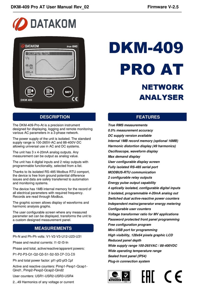
The DKM-409 is a precision instrument
designed for displaying various AC
parameters in 3-phase distribution panels.
The unit has 3 x 4-20mA analog outputs. Any
measurement can be output as analog value.
The unit has 4 digital inputs and 2 relay
outputs with programmable functionality,
selected from a list.
Thanks to its isolated RS-485 Modbus RTU
communication port, the device is free from
ground potential difference issues and
measured parameters are safely transferred
to automation systems.
* Electrical equipment should be installed
only by qualified specialist. No responsibility
is assured by the manufacturer or any of its
subsidiaries for any consequences resulting
from the non-compliance to these
instructions.
* Check the unit for cracks and damages due
to transportation. Do not install damaged
equipment.
* Do not open the unit. There is no
serviceable parts inside.
* Fuses of fast type (FF) with a maximum
rating of 6A must be connected to the power
supply and phase voltage inputs, in close
proximity of the unit.
* Disconnect all power before working on
equipment.
* When the unit is connected to the network
do not touch terminals.
* Short circuit terminals of unused current
transformers.
* Any electrical parameter applied to the
device must be in the range specified in the
user manual.
* Do not try to clean the device with solvent
or the like. Only clean with a dry cloth.
* Verify correct terminal connections before
applying power.
* Only for front panel mounting.
Before installation:
Read the user manual carefully, determine
the correct connection diagram.
Remove all connectors and mounting
brackets from the unit, then pass the unit
through the mounting opening.
Put mounting brackets and tighten. Do not
tighten too much, this can brake the
enclosure.
Make electrical connections with plugs
removed from sockets, then place plugs to
their sockets.
Note that the power supply terminal is
separated from measurement terminals.
Below conditions may damage the device:
Incorrect connections.
Incorrect power supply voltage.
Voltage at measuring terminals beyond
specified range.
Current at measuring terminals beyond
specified range.
Connecting or removing data terminals
when the unit is powered-up.
Overload or short circuit at relay outputs
Voltage applied to digital inputs over
specified range.
High voltage applied to communication port.
Below conditions may cause abnormal
operation:
Power supply voltage below minimum
acceptable level.
Power supply frequency out of specified
limits
Phase order of voltage inputs not correct.
Current transformers not matching related
phases.
Current transformer polarity incorrect.
Detailed user manual of this product
may be downloaded at:
www.datakom.com.tr
INSTALLATION
SAFETY NOTICE
Failure to follow below
instructions may result in
death or serious injury
DKM-409-PRO-AT NETWORK
ANALYSER WITH HARMONIC
MEASUREMENT AND SCOPEMETER
Although the unit is protected against
electromagnetic disturbance, excessive
disturbance can affect the operation,
measurement precision and data
communication quality.
Use cables of appropriate temperature
range.
Use adequate cable section, at least
0.75mm2 (AWG18).
For current transformer inputs, use at
least 1.5mm2section (AWG15) cable.
The current transformer cable length
should not exceed 1.5 meters. If longer
cable is used, increase the cable section
proportionally.
Current transformers must have 5A
output.

For the RS-485 connection, use
appropriate shielded twisted wire cable.
Communication quality will depend
highly on the cable used.
Three buttons on the front panel provide
access to configuration and measurement
screens.
BUTTON
FUNCTION
Selects next display group.
Press and hold for 3
seconds:
Removes alarms.
Selects next display screen
in the same display group.
Selects previous display
screen in the same display
group.
Press and hold for 10
seconds:
Current screen will be the
default display screen
Press and hold for 3
seconds:
Enable programming mode.
REQUIRED PANEL DEPTH
PUSHBUTTON FUNCTIONS
Do not install the unit close
to high electromagnetic
noise emitting devices like
contactors, high current
busbars, switchmode
power supplies and the
like.
ELECTRICAL INSTALLATION
In order to enable the
configuration menu, hold both
MENU buttons pressed for 3
seconds.
When the configuration mode is entered, the
password entry screen will be displayed.
A 4 digit password must be entered using
buttons. The factory default password is
“9876”. Each digit is adjusted with MENU
buttons and the next digit is selected with
SET button.
In order to exit the configuration
menu, hold both MENU buttons
pressed for 3 seconds.
If no button is pressed, the unit
will automatically close the
configuration menu after 30
seconds.
When the configuration mode is entered, a
list of available configuration topics will be
displayed as in the below screen.
Navigation on the list is made with MENU
buttons. Selected configuration topic is
shown in reverse video (black on white). In
order to enter inside a configuration topic,
please press SET button. In order to exit from
the group please press and hold SET button.
Parameter value may be increased and
decreased with MENU buttons.
Select LCD CONTRAST on CONTROLLER
CONFIG menu. Change the contrast value
with MENU buttons until best visibility is
obtained and then press SET to save new
LCD contrast value and return back to
“CONFIGURATION MENU”.
Select LANGUAGE on CONTROLLER
CONFIG menu. Select language with MENU
buttons then press SET to save the new
language and return to CONTROLLER
CONFIG menu.
For the correct current and power
measurement, the current transformer ratio
has to be set properly.
Both primary and secondary of the current
transformer is adjustable.
Select “CRNT TRF RATIO” on ELECTRICAL
PARAMS menu.
Then adjust the primary and secondary
current transformer ratios with MENU buttons
until required value then press SET button to
save the new current transformer ratio and
return to CONTROLLER CONFIG menu.
If a voltage transformer is used, then its ratio
needs to be set to the unit.
The voltage transformer ratio is defined as
primary voltage / secondary voltage. The
secondary is always supposed 1.0. Thus only
the primary is programmed.
Select VOLT TRF RATIO on CONTROLLER
CONFIG menu.
Adjust the voltage transformer ratio with
MENU buttons until required value then press
SET button to save new voltage transformer
ratio and return to CONTROLLER CONFIG
menu.
VOLTAGE TRANSFORMER RATIO
CURRENT TRANSFORMER RATIO
LANGUAGE SELECTION
ADJUSTING THE LCD CONTRAST
DEVICE CONFIGURATION
Supply Input: 100-240VAC (±15%), 50/60Hz
Measurement Inputs:
Voltage: 7 - 300 V AC (P-N)
14 - 520 V AC (P-P)
Current: 0.001 –6.00 A AC
Frequency: 30 - 100 Hz
Accuracy:
Voltage, current: 0.5% + 1 digit
Frequency: 0.5% + 1 digit
Power (kW,kVAr):1.0% + 2 digit
Cos: 0.5% + 1 digit
Withstanding:
Current: 100 A AC during 1 sec.
Voltage: 1300 V AC (continuous)
Analog Outputs: Active 4-20mA, 16 bit
Measurement Range:
CT range: 5/5A to 25000/5A
VT range: 0.1/1 to 5000.0/1
kW range: 1.0 kW to 5000 MW
Power Consumption: < 15 VA
Voltage Burden: < 0.02VA per phase
Current Burden: < 0.5VA per phase
Relay Outputs: 5A @ 250V AC
Digital Inputs:
Active level: 24 to 135V-DC or AC
Min pulse: 250ms.
Isolation: 1000V AC, 1 minute
Serial Port: RS-485, 2400-115200 bauds
Protocol: Modbus RTU
Isolation: 500V AC, 1 minute
Operating Temp. Range:
-20°C to +70 °C (-4°F to 158°F)
Max Humidity: 95%, non-condensing
IP Protection: IP 54 (Front), IP 30 (Back)
Enclosure: Non-flammable, ROHS compl.
Installation: Flush mounting
Dimensions: 102x102x53mm (WxHxD)
Panel Cutout: 92x92mm
Weight: 200 gr
EU Directives:
2006/95/EC (LVD)
2004/108/EC
(EMC)
Norms of Reference:
EN 61010 (safety)
EN 61326 (EMC)
UL-CSA Certification:
UL 61010-1, 3rd Edition, 2012-05,
CAN/CSA-C22.2
File: E475547, Vol. D1
TECHNICAL SPECIFICATIONS
CONNECTION DIAGRAM

Other Datakom Measuring Instrument manuals

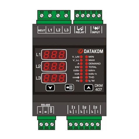
Datakom DKM-430 User manual

Datakom

Datakom DKM-430 User manual

Datakom DKM-409 PRO AT User manual

Datakom

Datakom DKM-409 PRO AT User manual

Datakom DPR-350 Series User manual

Datakom

Datakom DPR-350 Series User manual

Datakom DKM-409 User manual

Datakom

Datakom DKM-409 User manual

Datakom DKM-409 User manual

Datakom

Datakom DKM-409 User manual

Datakom DKM-260 User manual

Datakom

Datakom DKM-260 User manual

Datakom DKM-407 User manual

Datakom

Datakom DKM-407 User manual

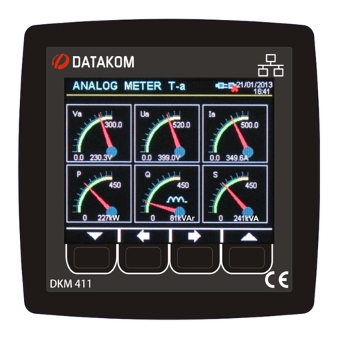
Datakom DKM-411 User manual

Datakom

Datakom DKM-411 User manual

Datakom DKM-411 User manual

Datakom

Datakom DKM-411 User manual

Datakom DKM-407 User manual

Datakom

Datakom DKM-407 User manual

Datakom DKM-411 Instructions for use

Datakom

Datakom DKM-411 Instructions for use

Datakom DV-0101 User manual

Datakom

Datakom DV-0101 User manual

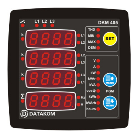
Datakom DKM-405 User manual

Datakom

Datakom DKM-405 User manual

Datakom DSD-080 User manual

Datakom

Datakom DSD-080 User manual

Datakom DPR-165 User manual

Datakom

Datakom DPR-165 User manual

Datakom DKM-409-S User manual

Datakom

Datakom DKM-409-S User manual

Datakom DKM-250 User manual

Datakom

Datakom DKM-250 User manual

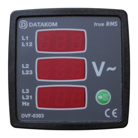
Datakom DVF-0303 User manual

Datakom

Datakom DVF-0303 User manual

Popular Measuring Instrument manuals by other brands

ABB GLA451 user manual

ABB

ABB GLA451 user manual

Ruskin TDP05K Technical bulletin

Ruskin

Ruskin TDP05K Technical bulletin

Carlson Boretrak2 user manual

Carlson

Carlson Boretrak2 user manual

Horex 22 117 16 operating instructions

Horex

Horex 22 117 16 operating instructions

Tektronix TLA7012 instructions

Tektronix

Tektronix TLA7012 instructions

TSI Instruments 3936 Operation and service manual

TSI Instruments

TSI Instruments 3936 Operation and service manual

MFJ MFJ-834 instruction manual

MFJ

MFJ MFJ-834 instruction manual

Topcon GM-100 Series Quick manual

Topcon

Topcon GM-100 Series Quick manual

eHealthcare H100 user manual

eHealthcare

eHealthcare H100 user manual

WYLER Clinotronic S quick reference

WYLER

WYLER Clinotronic S quick reference

DeWalt DW0802 instructions

DeWalt

DeWalt DW0802 instructions

SCADAmetrics EtherMeter EM-100 Installation, operation and maintenance manual

SCADAmetrics

SCADAmetrics EtherMeter EM-100 Installation, operation and maintenance manual

Keysight N1911A Programming guide

Keysight

Keysight N1911A Programming guide

Ecom CN operating instructions

Ecom

Ecom CN operating instructions

Mitsubishi Electric EcoMonitorPro EMU2-RD3-F instruction manual

Mitsubishi Electric

Mitsubishi Electric EcoMonitorPro EMU2-RD3-F instruction manual

ISOIL SBM 150 Operator's manual

ISOIL

ISOIL SBM 150 Operator's manual

Lasertec HV1G instruction manual

Lasertec

Lasertec HV1G instruction manual

AEMC 4500 user manual

AEMC

AEMC 4500 user manual

manuals.online logo
manuals.online logoBrands
  • About & Mission
  • Contact us
  • Privacy Policy
  • Terms and Conditions

Copyright 2025 Manuals.Online. All Rights Reserved.