manuals.online logo
Brands
  1. Home
  2. •
  3. Brands
  4. •
  5. Datalogic
  6. •
  7. Accessories
  8. •
  9. Datalogic LD46 User manual

Datalogic LD46 User manual

Other Datalogic Accessories manuals

Datalogic VS-CRX Installation and operation manual

Datalogic

Datalogic VS-CRX Installation and operation manual

Datalogic PowerScan BC9600 Series User manual

Datalogic

Datalogic PowerScan BC9600 Series User manual

Datalogic Matrix 300N Installation and operation manual

Datalogic

Datalogic Matrix 300N Installation and operation manual

Datalogic S8-MR M Series User manual

Datalogic

Datalogic S8-MR M Series User manual

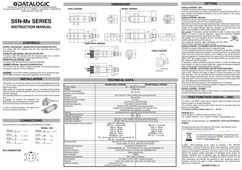
Datalogic S5N-PA User manual

Datalogic

Datalogic S5N-PA User manual

Datalogic SG-LP SERIES User manual

Datalogic

Datalogic SG-LP SERIES User manual

Datalogic S100W User manual

Datalogic

Datalogic S100W User manual

Datalogic Smart-VS WebApp User manual

Datalogic

Datalogic Smart-VS WebApp User manual

Datalogic S8-PH M53 Series User manual

Datalogic

Datalogic S8-PH M53 Series User manual

Datalogic STARGATE RF910MHz Quick start guide

Datalogic

Datalogic STARGATE RF910MHz Quick start guide

Datalogic S51-PA Series User manual

Datalogic

Datalogic S51-PA Series User manual

Datalogic BC9XX0-BT User manual

Datalogic

Datalogic BC9XX0-BT User manual

Datalogic S5N-M Series User manual

Datalogic

Datalogic S5N-M Series User manual

Datalogic S5N-PA User manual

Datalogic

Datalogic S5N-PA User manual

Datalogic TL46-WLF User manual

Datalogic

Datalogic TL46-WLF User manual

Datalogic S5N-PA User manual

Datalogic

Datalogic S5N-PA User manual

Datalogic SG4-RB2-050-OO-W User manual

Datalogic

Datalogic SG4-RB2-050-OO-W User manual

Datalogic Multi Purpose Holder User manual

Datalogic

Datalogic Multi Purpose Holder User manual

Datalogic S8-PR M53 Series User manual

Datalogic

Datalogic S8-PR M53 Series User manual

Datalogic TL46-WLF User manual

Datalogic

Datalogic TL46-WLF User manual

Datalogic IO-Link S5N-P Series User manual

Datalogic

Datalogic IO-Link S5N-P Series User manual

Datalogic BASIC HOLDER Technical manual

Datalogic

Datalogic BASIC HOLDER Technical manual

Datalogic IO-Link S100 Series User manual

Datalogic

Datalogic IO-Link S100 Series User manual

Datalogic S5N-PA W Series User manual

Datalogic

Datalogic S5N-PA W Series User manual

Popular Accessories manuals by other brands

Quincy lab 140AE-1 operating manual

Quincy lab

Quincy lab 140AE-1 operating manual

HomePro ZIR000 user manual

HomePro

HomePro ZIR000 user manual

DOL 20SCR Technical user guide

DOL

DOL 20SCR Technical user guide

RAB Smart Task installation manual

RAB

RAB Smart Task installation manual

Kemppi KMS 300 quick guide

Kemppi

Kemppi KMS 300 quick guide

Stearns 57,500 Series Installation and service instructions

Stearns

Stearns 57,500 Series Installation and service instructions

iGuzzini TWILIGHT COPENAGHEN manual

iGuzzini

iGuzzini TWILIGHT COPENAGHEN manual

Adelaide Annexe & Canvas Avan Deluxe installation guide

Adelaide Annexe & Canvas

Adelaide Annexe & Canvas Avan Deluxe installation guide

OHAUS 5000 instruction manual

OHAUS

OHAUS 5000 instruction manual

HOME8 WLS1300 quick start guide

HOME8

HOME8 WLS1300 quick start guide

MAXBOTIX MaxSonar quick start guide

MAXBOTIX

MAXBOTIX MaxSonar quick start guide

ioSmart iSmart56 Installation and user guide

ioSmart

ioSmart iSmart56 Installation and user guide

Focusrite Scarlett 18i8 user guide

Focusrite

Focusrite Scarlett 18i8 user guide

Velleman ED38105 user manual

Velleman

Velleman ED38105 user manual

JumpSport SkyBounce user manual

JumpSport

JumpSport SkyBounce user manual

Prima-Temp PRIYA Instructions for use

Prima-Temp

Prima-Temp PRIYA Instructions for use

Tefcold BC85I-BC85I W user manual

Tefcold

Tefcold BC85I-BC85I W user manual

Vaisala WMS302 user guide

Vaisala

Vaisala WMS302 user guide

manuals.online logo
manuals.online logoBrands
  • About & Mission
  • Contact us
  • Privacy Policy
  • Terms and Conditions

Copyright 2025 Manuals.Online. All Rights Reserved.

154 CATALOG | Photoelectric Sensors
LD
CATALOG
SECTION
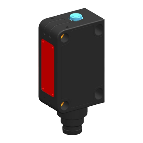
LD46
Luminescence sensor
10…20 mm (LD46-UL-715)
20…40 mm (LD46-UL-755)
30…50 mm (LD46-UL-735)
Spot dimension
2x8 mm at 10 mm
3x11 mm at 24 mm
4x15 mm at 50 mm
Switching frequency 2 kHz
Response Time 250 µs
Light emission UV-HP LED
Setting push buttons
Power supply
Vdc 15…30 V
Vac
Vac/dc
Output
PNP
NPN
NPN/PNP •
relay
other 0…5 V Analog output
Connection
cable
connector •
pig-tail
Approximate dimensions (mm) 31x81x58
Housing material aluminium
Mechanical protection IP67
(*) ATEX
II
3DG
APPLICATIONS
• Packaging and labeling machinery
• Food, Cosmetic and Pharmaceutical
• Ceramic tiles selection and sorting
LUMINESCENCE SENSOR
LINE IN STANDARD METAL
HOUSING
LD46
• UV high power LED emission
• High sensitivity on fluorescent marks
• 10 - 50 mm detection distance
• 2 kHz switching frequency
• NPN/PNP and 0-5 V analog outputs
LUMINESCENCE SENSORS
155
CATALOG | Photoelectric Sensors
TECHNICAL DATA
DIMENSIONS
LD46-UL
Luminescence sensor
INSTRUCTION MANUAL
CONTROLS
OUT LED (yellow)
The yellow LED indicates the output status.
READY LED (green)
During functioning, the green LED permanently ON
indicates a normal operating condition and blinking
indicates an output overload condition.
DELAY LED (orange)
The orange DELAY LED ON indicates the timing
function activation on the digital output.
KEYLOCK LED (orange)
The orange KEYLOCK LED ON indicates the active keyboard status.
BARGRAPH
The reading sensitivity level is signalled on the bargraph.
PUSH-BUTTON (white)
The pressing of the push-button unlocks the keyboard, memorises the
sensitivity and activates the digital output timing.
(red) and (green) push-buttons
The sensitivity adjustment procedure is activated by pressing the and
push-buttons.
See the “SETTING” paragraph for setup procedure indications.
INSTALLATION
The sensor can be positioned by means the two Ø3.5mm housing’s holes
using or threaded M5 holes with 6 mm max. depth.
Warning: the use of excessively long screws can damage the product.
The connector can be oriented at five different positions by rotating the block.
The position chosen is guaranteed by a mechanical blocking system.
The rotation can be carried-out even after sensor installation as the connector
block is completely self-contained inside the housing.
Operating distance is rated starting from the lens front face.
CONNECTIONS
TECHNICAL DATA
Power supply: 15…30 Vdc limits value
Ripple: 2 Vpp max.
Consumption
(output current excluded): 50mA max @ 24Vcc
Output: 1 PNP output
1 NPN output
Output current: 100 mA max.
Output saturation voltage: 2 V
Analogue output: 0.75 … 5.5 V max.
Analogue output
impedance:
2.2 k
(short-circuit protection)
Response time: 250 s
Switching frequency: 2 kHz
Delay: 0 / 20 ms selectable
(no-delay default configuration)
Indicators:
OUT LED (yellow) / READY LED (green)
DELAY LED and KEYLOCK LED (orange)
5-segment bargraph
Push-buttons: +, SET, -
Operating temperature: -10 … 55 °C
Storage temperature: -20 … 70 °C
Electric shock protection: double insulation
Operating distance:
10 … 20 mm (LD46-UL-715)
20 … 40 mm (LD46-UL-755)
30 … 50 mm (LD46-UL-735)
Minimum spot dimension:
2 x 8 mm @10mm (LD46-UL-715)
3x11 mm @ 24mm (LD46-UL-755)
4x15 mm @ 50mm(LD46-UL-735)
Emission type: UV 375nm LEDs, Class 1
Ambiente light rejection: according to EN 60947-5-2
Vibrations: 0.5 mm amplitude, 10 … 55 Hz frequency, per
each axis (EN60068-2-6)
Shock resistance: 11 ms (30 G) 6 shock per each axis
(EN60068-2-27)
Housing material: Aluminium
Lens material: Glass
Mechanical protection: IP67
Connections: M12 5-pole connector
Weight: 180 g. max.
SETTING
KEYLOCK function (patent-covered)
The KEYLOCK function deactivates the keyboard thus avoiding accidental
changes in the sensor setting.
At sensor powering the keyboard is blocked (KEYLOCK LED OFF). To
activate it, press for 5 seconds until the KEYLOCK LED (orange) turns
ON.
The keyboard is automatically blocked if not used for 2 minutes.
Unblock the keyboard to proceed with sensor adjustment.
NORMAL FUNCTIONING
During normal functioning a LED on the bargraph
visualises the sensitivity level.
SENSITIVITY ADJUSTMENT
This mode regulates the sensor reading sensitivity, i.e.
the capability of detecting objects with different
luminescence degrees.
The sensitivity is increased or decreased by pressing
the or push-buttons.
The adjustment speed is increased by keeping the
or push-buttons pressed.
The sensitivity level which is being set blinks on the bargraph during this
phase.
Sensitivity Bargraph
Low
Medium-Low
Medium
Medium-High
High
Press to memorise the new threshold value or wait 30sec for automatic
save.
DELAY SETTING
The DELAY extends the minimum active output status duration to 20ms,
allowing even slower interface systems to detect shorter pulses.
The delay is signalled by the corresponding orange LED ON.
Delay activation
-Press for 2 sec until DELAY LED turns ON.
Delay deactivation
-Press for 2 sec until DELAY LED turns
OFF.
OUTPUT OVERLOAD
The digital output overload is signalled by the rapid blinking of the READY
LED.
ANALOGUE OUTPUT
The analogue output supplies a voltage proportional to the signal received by
the sensor. The voltage supplied is 0.75 ÷ 5.5V.
DETECTION DIAGRAM
EX-II-3DG IP67 T6
Temperature class: T6 (<85°C)
Max. Power consumption: 1500 mW at 30 Vdc
Max. Internal capacitance: 380 pF
Internal inductance: negligible
DECLARATION OF CONFORMITY
We DATALOGIC AUTOMATION declare under our sole responsibility that these products are conform
to the 2004/108/CE and successive amendments.
WARRANTY
DATALOGIC AUTOMATION warrants its products to be free from defects.
DATALOGIC AUTOMATION will repair or replace, free of charge, any product found to be defective
during the warranty period of 36 months from the manufacturing date.
This warranty does not cover damage or liability deriving from the improper application of DATALOGIC
AUTOMATION products.
DATALOGIC AUTOMATION
V
ia Lavino 265 - 40050 Monte S.Pietro - Bologna – Italy
T
el: +39 051 6765611 - Fax: +39 051 6759324
w
ww.automation.datalogic.com e-mail:info.automation@datalogic.com
DATALOGIC AUTOMATION cares for the environment: 100% recycled paper.
DATALOGIC AUTOMATION reserves the right to make modifications and improvements without prior notification.
Datalogic and the Datalogic logo are registered trademarks of Datalogic S.p.A. in many countries,
including the U.S.A. and the E.U.
826003233 Rev.C © Copyright Datalogic 2007-2009
ON
OUT with DELAY
OFF 20ms 20ms
ON
OUT without DELAY
OFF
DIMENSIONS
Ø18.8
39.1
60.7
44.7
M20x0.75
M20x0.75
Ø25
M12x1
40
15.5
31.5
Ø18.8
28
Ø33
M20x0.75
Ø28
Ø18.8
24
28
N°2 M5 depth 6mm
3.5mm passing holes
4
21.5
25.4 8.5
LD46-UL-755
(22mm LENS)
LD46-UL-735
(40mm LENS)
LD46-UL-715
(9mm LENS)
mm
N°4 M5 depth 6mm max.
15.8
31.9
2
27.5
4.8
79
62.9
28
521
7.4
Power supply
15 … 30 Vdc (limit values)
Ripple
2 Vpp max.
Consumption (output current excluded) 50 mA max. at 24 Vdc
Light emission UV LED 375 nm
Setting SET push-buttons
Indicators
yellow OUTPUT LED
green READY LED
orange DELAY LED and KEYLOCK LED
5-segment bargraph
Output PNP/NPN; analog output
Output current 100 mA max.
Saturation voltage 2 V max.
Response time 250 µs
Switching frequency 2 kHz
Connection M12 5-pole connector
Dielectric strength 500 Vac, 1 min between electronics and housing
Insulating resistance >20 MΩ, 500 Vdc between electronics and housing
Electrical protection class 2, double insulation
Mechanical protection IP67
Ambient light rejection according to EN 60947-5-2
Vibrations 0,5 mm amplitude, 10 … 55 Hz frequency, for every axis (EN60068-2-6)
Shock resistance 11 ms (30 G) 6 shock for every axis (EN60068-2-27)
Minimum spot dimension
2 x 8 mm at 10 mm (mod. LD46-UL-715)
3x11 mm at 24 mm (mod. LD46-UL-755)
4x15 mm at 50 mm (mod. LD46-UL-735)
Housing material aluminium
Lens material glass
Operating temperature -10 … 55 °C
Storage temperature -20 … 70 °C
Weight 180 g max.
156 CATALOG | Photoelectric Sensors
G
F
A
C
D
E
B
ABC D
LD46-UL
E
FGF
N°. FORMAT 1 2 3 4
input REMOTE A 0V 0V +V +V
input REMOTE B 0V +V 0V +V
OUT without TIMER
OUT with TIMER
ON
OFF
20 ms
ON
OFF
ON
OFF
ON
OFF
20 ms
TLSERIES
INSTRUCTION MANUAL
CONTROLS
OUTPUT LED
The red LED indicates the output status.
READY LED
During functioning, the green LED permanently ON indicates a normal
operating condition; fast blinking indicates an output overload condition.
See the “SETTING” paragraph for setup procedure indications.
MARK / BKGD PUSHBUTTON
The pushbutton activates the setup procedure.
INSTALLATION
Operating distance is rated
starting from the lens front face.
The M12 connector or cable exit
can be rotated in three positions
by loosening the locking screw.
Tighten the locking screw when
finished.
The beam direction may be
changed swapping the cap and
the lens.
Detecting marks on a reflective surface is improved adjusting the beam
direction to 5° … 20° from surface axis.
CONNECTIONS
+10 … 30 Vdc
REMOTE A *
BROWN
RED
ORANGE
GREY
REMOTE B *
ANALOG OUTPUT
WHITE
BLUE
NPN/PNP
0 V
SHIELD **
*= Connect the unused REMOTE wires to 0 V.
** = The cable shield is insulated from the sensor housing; it is recommended
to connect the shield to 0 V.
M12 CONNECTOR
10 … 30 Vdc
-
+
NPN/PNP
0 V
ANALOG OUTPUT
(WHITE) (BROWN)
(BLUE) (BLACK)
2
3
1
4
DIMENSIONS
7.5
Ø25
READY LED OUTPUT LED
BKGD
PUSHBUTTON
.
mm
Ø25
31
n°.4 M5x6
n°.4 M5x0.24
81.2
14.1 27.5 28
42.2
58
36.6 28
n°.4 M5x6
n°.4 M5x0.24
39.8
24
4.3
M12 CONNECTOR
15
M12x1
20.9
Ø6.1
4.3
CAP
9 mm LENS
TL-x6x
18 mm LENS
MARK
PUSHBUTTON
TECHNICAL DATA
Power supply: 10 … 30 Vdc limit values; reverse polarity protection
Ripple: 2 Vpp max.
Current consumption
(output current excluded): 80 mA max.
Output: NPN or PNP, pull down/up resistance 10 k(short-circuit protection)
Output current: 200 mA max.
Analog output: 0 … 2 V ± 10% (white 90%); 5.5 V max.; ripple 40 mVpp max.; output resistance 2.2 k
Output saturation voltage: 1V max. NPN versions / 2V max PNP versions
Response time: 50 s max. / 25 s max. (TL-4xx/5xx)
Switching frequency: 10 kHz max. / 20 kHz max. (TL-4xx/5xx)
Timing function: 20 ms minimum output ON
Indicators: OUTPUT LED (RED) / READY LED (GREEN)
Setting: by pushbuttons / by wires; 4 settings storage cable version
Retention data: non volatile EEPROM memory
Operating temperature: -10 … 55 °C
Storage temperature: -20 … 70 °C
Electric shock protection: Class 1
Operating distance: 9 mm (TL-x1x/4xx/5xx) / 18 mm (TL-x6x)
Minimum spot dimension: 1.5 x 5 mm (TL-x1x) / 2 x 7 mm (TL-x6x) / 3 mm (TL-4xx/5xx)
Depth of field: ± 3 mm (TL-x1x/4xx/5xx) / ± 4 mm (TL-x6x)
Emission type: green (526 nm) / red (630 nm) with automatic selection or white (400-700 nm)
Ambient light rejection: according to EN 60947-5-2
Vibration: 0.5 mm amplitude, 10 … 55 Hz frequency, in every axis (EN60068-2-6)
Shock resistance: 11 ms (30 G) 6 shock in every axis (EN60068-2-27)
DARK/LIGHT selection: teach-in procedure
Housing: ZAMA
Protection class: IP67
Connections: 3 m shielded cable 6.1 mm / M12 4-pole connector
Weight: 450 g. max. cable versions / 310 g. max. connector versions
CONFIGURATION DETECTION DIAGRAM
A double selector and a switch are
available removing the sensor side
cover. The selector allows to enable the
output timing function and choose the
pushbuttons and REMOTE inputs 1 2
ON
REMOTE
SET
FORMAT
TIMING
ON
OFF
operating mode; the switch allows to select the output type (NPN o
r
PNP).
0
20
40
60
80
100
0 2 4 6 8 10 12 26 28
20 22 24
Operating distance
Relative sensitivity
TL -x1x/4xx/5xx
%
mm
16 18 30
14

TL -x6x
FUNCTION SELECTION
When FORMAT is
selected (configuration
selector section 1), the
MARK and BKGD
puskbuttons are enabled and connecting the REMOTE inputs (TL-xx1)
to the power supply as shown in the table allows to select up to 4
different settings (formats). This is the factory setting.
If a non-set format is selected, the sensor is disabled and the green LED
flashes at a low rate.
A setting can be stored selecting a format and executing the procedure
described in the “SETTING” paragraph.
When SET is selected (configuration selector section 1), the MARK and
BKGD pushbuttons are disabled; the REMOTE inputs (TL-x1x) replace
the pushbuttons functionality.
Connecting the REMOTE A and B inputs to the positive power supply
rail is equivalent to pressing the MARK and BKGD pushbuttons
respectively. Connect the unused inputs to 0V.
TIMING FUNCTION
When ON is selected
(configuration selector
section 2), a delay timer
function is enabled which
extends the minimum ON
output time to 20 ms. The factory setting is OFF (timer disabled).
SETTING
A two-step setup procedure adjusts the switching threshold and the
LIGHT/DARK mode. Using the procedure given below the sensor output
is set to be ON when a mark is detected.
1) Output ON state acquisition (MARK)
Place the target mark into the emission spot and press the MARK
pushbutton until the green LED turns OFF.
Don’t move the mark during the setting phase (about 1 sec).
2) Output OFF state acquisition (BKGD)
Place the background into the emission spot and press the BKGD
pushbutton; the green LED blinks once.
Don’t move the background during the setting phase.
If the green LED lights permanently ON, a safe operation has been
obtained; if it flashes at a low rate the setup procedure has failed due to
insufficient contrast; repeat the procedure from the beginning.
DECLARATION OF CONFORMITY
We DATALOGIC AUTOMATION declare under our sole responsibility
that these products are conform to the 2004/108/CE and successive
amendments.
WARRANTY
DATALOGIC AUTOMATION warrants its products to be free from
defects.
DATALOGIC AUTOMATION will repair or replace, free of charge, any
product found to be defective during the warranty period of 36 months
from the manufacturing date.
This warranty does not cover damage or liability deriving from the
improper application of DATALOGIC AUTOMATION products.
DATALOGIC AUTOMATION
V
ia Lavino 265 - 40050 Monte S.Pietro - Bologna – Italy
T
el: +39 051 6765611 - Fax: +39 051 6759324
w
ww.automation.datalogic.com e-mail:info.automation.it@datalogic.com
DATALOGIC AUTOMATION cares for the environment: 100% recycled paper.
DATALOGIC AUTOMATION reserves the right to make modifications and
improvements without prior notification.
Datalogic and the Datalogic logo are registered trademarks of Datalogic
S.p.A. in many countries, including the U.S.A. and the E.U.
826000025 Rev.G © Copyright Datalogic 2007-2009
Standard 9 mm lens
(2 x 8 mm spot at 10 mm)
Standard 22 mm lens
(3 x 11 mm spot at 24 mm)
Standard 40 mm lens
(4 x 15 mm spot at 50 mm)
mm mm mm
+/- push-buttons
SET push-button
yellow OUTPUT LED
green READY LED
orange DELAY LED
orange KEYLOCK LED
Bargraph
M12 CONNECTOR
INDICATORS AND SETTINGS
CONNECTIONS
DETECTION DIAGRAMS
157
LD46-UL
Luminescence sensor
INSTRUCTION MANUAL
CONTROLS
OUT LED (yellow)
The yellow LED indicates the output status.
READY LED (green)
During functioning, the green LED permanently ON
indicates a normal operating condition and blinking
indicates an output overload condition.
DELAY LED (orange)
The orange DELAY LED ON indicates the timing
function activation on the digital output.
KEYLOCK LED (orange)
The orange KEYLOCK LED ON indicates the active keyboard status.
BARGRAPH
The reading sensitivity level is signalled on the bargraph.
PUSH-BUTTON (white)
The pressing of the push-button unlocks the keyboard, memorises the
sensitivity and activates the digital output timing.
(red) and (green) push-buttons
The sensitivity adjustment procedure is activated by pressing the and
push-buttons.
See the “SETTING” paragraph for setup procedure indications.
INSTALLATION
The sensor can be positioned by means the two Ø3.5mm housing’s holes
using or threaded M5 holes with 6 mm max. depth.
Warning: the use of excessively long screws can damage the product.
The connector can be oriented at five different positions by rotating the block.
The position chosen is guaranteed by a mechanical blocking system.
The rotation can be carried-out even after sensor installation as the connector
block is completely self-contained inside the housing.
Operating distance is rated starting from the lens front face.
CONNECTIONS
TECHNICAL DATA
Power supply: 15…30 Vdc limits value
Ripple: 2 Vpp max.
Consumption
(output current excluded): 50mA max @ 24Vcc
Output: 1 PNP output
1 NPN output
Output current: 100 mA max.
Output saturation voltage: 2 V
Analogue output: 0.75 … 5.5 V max.
Analogue output
impedance:
2.2 k
(short-circuit protection)
Response time: 250 s
Switching frequency: 2 kHz
Delay: 0 / 20 ms selectable
(no-delay default configuration)
Indicators:
OUT LED (yellow) / READY LED (green)
DELAY LED and KEYLOCK LED (orange)
5-segment bargraph
Push-buttons: +, SET, -
Operating temperature: -10 … 55 °C
Storage temperature: -20 … 70 °C
Electric shock protection: double insulation
Operating distance:
10 … 20 mm (LD46-UL-715)
20 … 40 mm (LD46-UL-755)
30 … 50 mm (LD46-UL-735)
Minimum spot dimension:
2 x 8 mm @10mm (LD46-UL-715)
3x11 mm @ 24mm (LD46-UL-755)
4x15 mm @ 50mm(LD46-UL-735)
Emission type: UV 375nm LEDs, Class 1
Ambiente light rejection: according to EN 60947-5-2
Vibrations: 0.5 mm amplitude, 10 … 55 Hz frequency, per
each axis (EN60068-2-6)
Shock resistance: 11 ms (30 G) 6 shock per each axis
(EN60068-2-27)
Housing material: Aluminium
Lens material: Glass
Mechanical protection: IP67
Connections: M12 5-pole connector
Weight: 180 g. max.
SETTING
KEYLOCK function (patent-covered)
The KEYLOCK function deactivates the keyboard thus avoiding accidental
changes in the sensor setting.
At sensor powering the keyboard is blocked (KEYLOCK LED OFF). To
activate it, press for 5 seconds until the KEYLOCK LED (orange) turns
ON.
The keyboard is automatically blocked if not used for 2 minutes.
Unblock the keyboard to proceed with sensor adjustment.
NORMAL FUNCTIONING
During normal functioning a LED on the bargraph
visualises the sensitivity level.
SENSITIVITY ADJUSTMENT
This mode regulates the sensor reading sensitivity, i.e.
the capability of detecting objects with different
luminescence degrees.
The sensitivity is increased or decreased by pressing
the or push-buttons.
The adjustment speed is increased by keeping the
or push-buttons pressed.
The sensitivity level which is being set blinks on the bargraph during this
phase.
Sensitivity Bargraph
Low
Medium-Low
Medium
Medium-High
High
Press to memorise the new threshold value or wait 30sec for automatic
save.
DELAY SETTING
The DELAY extends the minimum active output status duration to 20ms,
allowing even slower interface systems to detect shorter pulses.
The delay is signalled by the corresponding orange LED ON.
Delay activation
-Press for 2 sec until DELAY LED turns ON.
Delay deactivation
-Press for 2 sec until DELAY LED turns
OFF.
OUTPUT OVERLOAD
The digital output overload is signalled by the rapid blinking of the READY
LED.
ANALOGUE OUTPUT
The analogue output supplies a voltage proportional to the signal received by
the sensor. The voltage supplied is 0.75 ÷ 5.5V.
DETECTION DIAGRAM
EX-II-3DG IP67 T6
Temperature class: T6 (<85°C)
Max. Power consumption: 1500 mW at 30 Vdc
Max. Internal capacitance: 380 pF
Internal inductance: negligible
DECLARATION OF CONFORMITY
We DATALOGIC AUTOMATION declare under our sole responsibility that these products are conform
to the 2004/108/CE and successive amendments.
WARRANTY
DATALOGIC AUTOMATION warrants its products to be free from defects.
DATALOGIC AUTOMATION will repair or replace, free of charge, any product found to be defective
during the warranty period of 36 months from the manufacturing date.
This warranty does not cover damage or liability deriving from the improper application of DATALOGIC
AUTOMATION products.
DATALOGIC AUTOMATION
V
ia Lavino 265 - 40050 Monte S.Pietro - Bologna – Italy
T
el: +39 051 6765611 - Fax: +39 051 6759324
w
ww.automation.datalogic.com e-mail:info.automation@datalogic.com
DATALOGIC AUTOMATION cares for the environment: 100% recycled paper.
DATALOGIC AUTOMATION reserves the right to make modifications and improvements without prior notification.
Datalogic and the Datalogic logo are registered trademarks of Datalogic S.p.A. in many countries,
including the U.S.A. and the E.U.
826003233 Rev.C © Copyright Datalogic 2007-2009
ON
OUT with DELAY
OFF 20ms 20ms
ON
OUT without DELAY
OFF
DIMENSIONS
Ø18.8
39.1
60.7
44.7
M20x0.75
M20x0.75
Ø25
M12x1
40
15.5
31.5
Ø18.8
28
Ø33
M20x0.75
Ø28
Ø18.8
24
28
N°2 M5 depth 6mm
3.5mm passing holes
4
21.5
25.4 8.5
LD46-UL-755
(22mm LENS)
LD46-UL-735
(40mm LENS)
LD46-UL-715
(9mm LENS)
mm
N°4 M5 depth 6mm max.
15.8
31.9
2
27.5
4.8
79
62.9
28
521
7.4
OPTIC FUNCTION EMISSION CONNECTION OUTPUT MODEL ORDER No.
Luminescence sensor
10-20 mm Vertical spot
M12 Connector NPN/PNP
LD46-UL-715 955201000
20-40 mm Vertical spot LD46-UL-755 955201010
30-50 mm Vertical spot LD46-UL-735 955201020
MODEL DESCRIPTION ORDER No.
Lens No.9 glass lens with 9 mm focus 95ACC2670
Lens No.22 glass lens with 22 mm focus 95ACC1100
Lens No.40 glass lens with 40 mm focus 95ACC2740
Lens No.50 glass lens with 50 mm focus S73030511
22 mm LENS
LD46UL755
9 mm LENS
LD46UL715
40 mm LENS
LD46UL735
50 mm LENS
TYPE DESCRIPTION LENGTH MODEL ORDER No.
Axial M12 Connector
5-pole, grey, P.V.C.
3 m CS-A1-03-G-03 95ACC2110
5 m CS-A1-03-G-05 95ACC2120
10 m CS-A1-03-G-10 95ACC2140
5-pole, U.L., black, P.V.C
3 m CS-A1-03-U-03 95ASE1170
5 m CS-A1-03-U-05 95ASE1180
10 m CS-A1-03-U-10 95ASE1190
15 m CS-A1-03-U-15 95ASE1200
25 m CS-A1-03-U-25 95ASE1210
50 m CS-A1-03-U-50 95A252700
MODEL SELECTION AND ORDER INFORMATION
ACCESSORIES
CABLES
The company endeavours to continuously improve and renew its products; for this reason the technical data and contents of this catalogue may undergo variations without prior notice. For correct installation and use,
the company can guarantee only the data indicated in the instruction manual supplied with the products. Product and Company names and logos referenced may be either trademarks or registered trademarks of their
respective companies. We reserve the right to make modifications and improvements.
Rev. 03, 04/2019