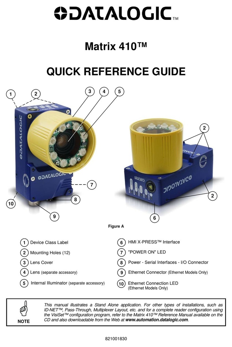
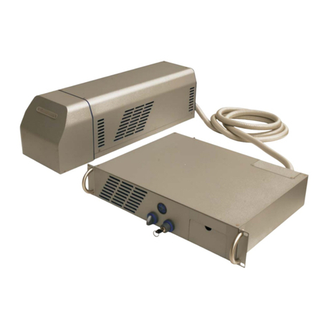
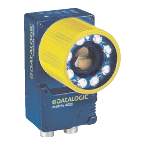
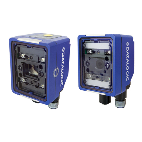
Datalogic matrix 450N Installation and operation manual

Matrix 450N™
PRODUCT REFERENCE GUIDE
Image Based Reader

Datalogic S.r.l.
Via S. Vitalino, 13
40012 Calderara di Reno (BO)
Italy
Tel. +39 051 3147011
Fax +39 051 3147205
© 2016-2020 Datalogic S.p.A. and /or its affiliates
All rights reserved. Without limiting the rights under copyright, no part of this documentation may be repro-
duced, stored in or introduced into a retrieval system, or transmitted in any form or by any means, or for any
purpose, without the express written permission of Datalogic S.p.A. and/or its affiliates.
Owners of Datalogic products are hereby granted a non-exclusive, revocable license to reproduce and
transmit this documentation for the purchaser's own internal business purposes. Purchaser shall not
remove or alter any proprietary notices, including copyright notices, contained in this documentation and
shall ensure that all notices appear on any reproductions of the documentation.
Electronic versions of this document may be downloaded from the Datalogic website (www.datalogic.com).
If you visit our website and would like to make comments or suggestions about this or other Datalogic pub-
lications, please let us know via the "Contact" page.
Disclaimer
Datalogic has taken reasonable measures to provide information in this manual that is complete and accu-
rate, however, Datalogic shall not be liable for technical or editorial errors or omissions contained herein,
nor for incidental or consequential damages resulting from the use of this material. Datalogic reserves the
right to change any specification at any time without prior notice.
Trademarks
Datalogic and the Datalogic logo are registered trademarks of Datalogic S.p.A. in many countries, including
the U.S.A. and the E.U.
Matrix 450N, ID-NET, DL.CODE, X-PRESS and Blue Diamonds are trademarks of Datalogic S.p.A. and/or its
affiliates. All other trademarks and brands are property of their respective owners.
Patents
See www.patents.datalogic.com for patent list.

PRODUCT REFERENCE GUIDE
iii
CONTENTS
PREFACE .................................................................................................................VII
About this Manual .......................................................................................................... vii
Manual Conventions .......................................................................................................................... vii
Technical Support .......................................................................................................... vii
Support Through the Website ........................................................................................................... vii
Reseller Technical Support .............................................................................................................. viii
COMPLIANCE ............................................................................................................IX
General .......................................................................................................................... ix
Power Supply ................................................................................................................. ix
EMC Compliance ............................................................................................................. ix
CE Compliance ................................................................................................................ ix
FCC Compliance ............................................................................................................... x
EAC Compliance ............................................................................................................... x
LT-03X Laser Safety ....................................................................................................... xi
LED Safety .....................................................................................................................xi
HANDLING ...............................................................................................................XII
GENERAL VIEW.......................................................................................................XIV
RAPID CONFIGURATION..............................................................................................1
Step 1 - Assemble the Reader .......................................................................................... 1
Required Accessories .........................................................................................................................3
Step 2 - Connect the System ............................................................................................ 4
CBX100/CBX500 Pinout for Matrix 450N ...........................................................................................6
Step 3 - Mount and Position the Reader ............................................................................7
Step 4 - Focus the Reader ................................................................................................ 9
Step 5 - Calibrate Image Density .................................................................................... 10
Locate ........................................................................................................................................10
Setup ..........................................................................................................................................11
Learn ..........................................................................................................................................12
Step 6 - X-PRESS Configuration ..................................................................................... 13
Locate ........................................................................................................................................13
Setup ..........................................................................................................................................13
Learn ..........................................................................................................................................14
Reset Reader to Factory Default Environment (Optional) ...............................................................15
Step 7 - Installing DL.CODE Configuration Program ......................................................... 16
Device Discovery ...............................................................................................................................17
Step 8 - Device Configuration ......................................................................................... 20
Automatic or Advanced Setup ..........................................................................................................20
Automatic Setup .......................................................................................................................21
Advanced Setup .........................................................................................................................23
Reading Phase ...........................................................................................................................30
Good Read Setup .......................................................................................................................31
Data Formatting ........................................................................................................................32
Output Setup .............................................................................................................................33
Step 9 - Test Mode ......................................................................................................... 34
Advanced Reader Configuration ...................................................................................... 35
Host Mode Programming .................................................................................................................35

CONTENTS
iv
MATRIX 450N
INTRODUCTION ........................................................................................................ 36
Product Description ........................................................................................................36
Standard Application Program .........................................................................................................37
Excellent Performance .....................................................................................................................37
Ease of Setup .....................................................................................................................................37
Ease of Use ........................................................................................................................................38
Flexible Solution ................................................................................................................................38
Industrial Strength ............................................................................................................................38
Indicator and Keypad Button ...........................................................................................39
ID-NET ..........................................................................................................................40
X-PRESS Human Machine Interface ................................................................................42
X-PRESS Functions ...........................................................................................................................43
Test Mode ..................................................................................................................................43
Focus/Locate ............................................................................................................................44
Setup .........................................................................................................................................44
Learn .........................................................................................................................................44
Diagnostic Indication .........................................................................................................................45
Model Description ...........................................................................................................45
Lens/Illuminator Selection ...............................................................................................................45
Accessories ....................................................................................................................46
Application Examples .....................................................................................................49
Manual Postal Sorting ......................................................................................................................49
Loading/Unloading ............................................................................................................................49
Automated Postal Sorting ................................................................................................................50
Multimedia and Flats ........................................................................................................................51
Order Fulfillment ...............................................................................................................................51
Static Scan .........................................................................................................................................52
Manual Presentation Scan ................................................................................................................52
INSTALLATION......................................................................................................... 53
Package Contents ...........................................................................................................53
Mechanical Dimensions ...................................................................................................54
Mounting And Positioning Matrix 450N ............................................................................56
Mounting with EMK Mirrors ............................................................................................59
EMK-380 Side Mount - Standard .....................................................................................................60
EMK-380 Side Mount - Alternative ..................................................................................................61
EMK-600 Side Mount - Standard .....................................................................................................62
EMK-600 Side Mount - Alternative ..................................................................................................63
CBX ELECTRICAL CONNECTIONS.............................................................................. 64
CBX Connection Box Pinout .............................................................................................65
Power Supply .................................................................................................................66
Recommended Power Supplies .......................................................................................................67
Main Serial Interface ......................................................................................................68
RS232 Interface .................................................................................................................................68
RS422 Full Duplex Interface .............................................................................................................69
ID-NET Interface ............................................................................................................70
ID-NET Cables ...................................................................................................................................70
ID-NET Response Time .....................................................................................................................71
ID-NET Network Termination ..........................................................................................................72
ID-NET Connection Diagrams ..........................................................................................................72
Auxiliary RS232 Interface ...............................................................................................75
Inputs ............................................................................................................................76
External Trigger Input Connections Using Matrix 450N Power ......................................................77
External Trigger Input Connections Using External Power ............................................................79
Input 2 Connections Using CBX Power ............................................................................................80
Input 2 Connections Using External Power .....................................................................................81
Outputs ..........................................................................................................................82
Output 1 and 2 Connections Using CBX Power ................................................................................83
Output 1 and 2 Connections Using External Power ........................................................................84
On-Board GIGABIT Ethernet Interface .............................................................................85
User Interface - Serial Host ............................................................................................85


CONTENTS
PRODUCT REFERENCE GUIDE
v
TYPICAL LAYOUTS ...................................................................................................86
Ethernet Connection ....................................................................................................... 87
Serial Connection ........................................................................................................... 89
Fieldbus Connection ....................................................................................................... 90
Pass-Through ................................................................................................................ 91
ID-NET Multidata Network (Pass-Through) ..................................................................... 92
ID-NET Synchronized Network ....................................................................................... 93
READING FEATURES ................................................................................................96
FOV Calculation ............................................................................................................. 96
Reading Diagrams .......................................................................................................... 98
Matrix 450N + LNS-1216 ..................................................................................................................99
Matrix 450N + LNS-1225 ................................................................................................................100
Maximum Line Speed and Exposure Time Calculations .................................................. 108
SOFTWARE CONFIGURATION .................................................................................. 110
DL.CODE System Requirements .................................................................................... 110
Reader Configuration ................................................................................................... 110
Auto-Calibration ..............................................................................................................................111
Manual Calibration ..........................................................................................................................112
Under-exposure ......................................................................................................................112
Over-exposure ........................................................................................................................113
Moving code out of the Field of View .....................................................................................114
Multi Image Acquisition Settings ................................................................................... 115
Automatic Image Settings Selection ..............................................................................................116
External Image Settings Selection .................................................................................................117
Image Cropping ............................................................................................................ 119
Direct Part Marking Applications ................................................................................... 122
Image Filter .....................................................................................................................................123
Pass-Through Configurations ........................................................................................ 127
Internal Network Configurations ................................................................................... 129
Master Configuration ......................................................................................................................130
Multidata ID-NET Network Configurations ....................................................................................132
Synchronized ID-NET Network Configurations .............................................................................137
Verify Master/Slave Synchronized Configuration ..........................................................................141
Backup and Restore Through DL.CODE ......................................................................... 144
Backup .............................................................................................................................................145
Restore ............................................................................................................................................146
Replacement ....................................................................................................................................146
Restore Defaults .......................................................................................................... 147
Restore Default Startup Configuration ...........................................................................................147
Restore Default Environment .........................................................................................................148
Restore Factory Defaults ................................................................................................................148
Diagnostic Alarms ........................................................................................................ 149
Statistics .....................................................................................................................150
BM150 Display Module Configuration and Messages ...................................................... 151
Configuration Through DL.CODE ....................................................................................................151
Accessing the HMI Interface Through Keypad and Display Menu .................................................152
Display Messages ............................................................................................................................154
BM150 Backup and Restore Procedure .........................................................................................157
MAINTENANCE....................................................................................................... 158
Cleaning ...................................................................................................................... 158
TROUBLESHOOTING ............................................................................................... 159
General Guidelines ....................................................................................................... 159
TECHNICAL FEATURES........................................................................................... 162
ALTERNATIVE CONNECTIONS................................................................................. 165
Power, Com and I/O Connector for Standard Models ...................................................... 165
Matrix 450N Lighting System Control Connector ............................................................ 167
LT-03x Input Power Connector (on LT-03x) .................................................................. 168
Recommended Power Supplies .....................................................................................................169
Matrix 450N GigaEthernet Connector (**) .................................................................... 170

CONTENTS
vi
MATRIX 450N
ID-NET Network Termination ........................................................................................ 171
Inputs ..........................................................................................................................171
Outputs ........................................................................................................................172
User Interface - Serial Host ..........................................................................................174
GLOSSARY............................................................................................................. 175

PRODUCT REFERENCE GUIDE VII
PREFACE
ABOUT THIS MANUAL
This Product Reference Guide (PRG) is provided for users seeking advanced technical
information, including connection, programming, maintenance and specifications. The
Quick Reference Guide (QRG) and other publications associated with this product can
be downloaded free of charge from the website listed on the back cover of this manual.
Manual Conventions
The following conventions are used in this document:
The symbols listed below are used in this manual to notify the reader of key issues or
procedures that must be observed when using the reader:
NOTE
TECHNICAL SUPPORT
Support Through the Website
Datalogic provides several services as well as technical support through its website. Log
on to (www.datalogic.com).
For quick access, from the home page click on the search icon , and type in the name of
the product you’re looking for. This allows you access to download Data Sheets, Manu-
als, Software & Utilities, and Drawings.
Hover over the Support & Service menu for access to Services and Technical Support.
Notes contain information necessary for properly diagnosing, repairing and
operating the reader.
CAUTION
The CAUTION symbol advises you of actions that could damage equipment or property.
WARNING
The WARNING symbol advises you of actions that could result in harm or
injury to the person performing the task.

VIII MATRIX 450N
Reseller Technical Support
An excellent source for technical assistance and information is an authorized Datalogic
reseller. A reseller is acquainted with specific types of businesses, application software,
and computer systems and can provide individualized assistance.

PRODUCT REFERENCE GUIDE IX
COMPLIANCE
GENERAL
For installation, use and maintenance it is not necessary to open the reader.
Only connect Ethernet and dataport connections to a network which has routing only
within the plant or building and no routing outside the plant or building.
POWER SUPPLY
ATTENTION: READ THIS INFORMATION BEFORE INSTALLING THE PRODUCT
This product is intended to be installed by Qualified Personnel only.
This product is intended to be connected to a UL Listed Direct Plug-in Power Unit
marked LPS or “Class 2”.
EMC COMPLIANCE
In order to meet the EMC requirements:
• connect reader chassis to the plant earth ground by means of a flat copper braid
shorter than 100 mm;
• for CBX connections, connect pin "Earth" to a good Earth Ground;
• for direct connections, connect your cable shield to the locking ring nut of the con-
nector.
CE COMPLIANCE
CE marking states the compliance of the product with essential requirements listed in
the applicable European directive. Since the directives and applicable standards are
subject to continuous updates, and since Datalogic promptly adopts these updates,
therefore the EU declaration of conformity is a living document. The EU declaration of
conformity is available for competent authorities and customers through Datalogic
commercial reference contacts. Since April 20th, 2016 the main European directives
applicable to Datalogic products require inclusion of an adequate analysis and assess-
ment of the risk(s). This evaluation was carried out in relation to the applicable points of
the standards listed in the Declaration of Conformity. Datalogic products are mainly
designed for integration purposes into more complex systems. For this reason it is under
the responsibility of the system integrator to do a new risk assessment regarding the
final installation.
Warning:
This is a Class A product. In a domestic environment this product may cause
radio interference in which case the user may be required to take adequate measures.

X MATRIX 450N
FCC COMPLIANCE
Modifications or changes to this equipment without the expressed written approval of
Datalogic could void the authority to use the equipment.
This device complies with PART 15 of the FCC Rules. Operation is subject to the follow-
ing two conditions: (1) This device may not cause harmful interference, and (2) this
device must accept any interference received, including interference which may cause
undesired operation.
This equipment has been tested and found to comply with the limits for a Class A digital
device, pursuant to part 15 of the FCC Rules. These limits are designed to provide rea-
sonable protection against harmful interference when the equipment is operated in a
commercial environment. This equipment generates, uses, and can radiate radio fre-
quency energy and, if not installed and used in accordance with the instruction manual,
may cause harmful interference to radio communications. Operation of this equipment
in a residential area is likely to cause harmful interference in which case the user will be
required to correct the interference at his/her own expense.
EAC COMPLIANCE
Customs Union:
The CU Conformity certification has been achieved; this allows the Product to bear the
Eurasian Mark of conformity.

PRODUCT REFERENCE GUIDE XI
LT-03X LASER SAFETY
The LT-03x Series Lighting Systems contain two aiming Laser LEDs used to position the
reader.
This product conforms to the applicable requirements of IEC 60825-1 and complies with
21 CFR 1040.10 except for deviations pursuant to Laser Notice N° 50, date June 24,
2007. This product is classified as a Class 2 laser product according to IEC 60825-1 regu-
lations.
Disconnect the power supply when opening the device during maintenance or installa-
tion to avoid exposure to hazardous laser light. The laser beam can be switched on or
off through a software command.
The following warning label content is applied to each of the laser equipped products
indicated in the General View illustration (Figure 1).
Example Laser Warning Labels
Produit(s) conforme selon 21CFR 1040.10 sauf des dérogations relatives à la Laser
Notice N° 50, data Juin 24, 2007.
Dans le paquet il y a l’étiquette(s) pour les pays où le texte d’avertissement en français
est obligatoire. Le(s) mettre sur le produit à la place de la version anglaise.
Exemple d’étiquettes d’avertissement laser
LED SAFETY
LT-03x LED emission according to EN 62471.
CAUTION
Use of controls or adjustments or performance of procedures other than
those specified herein may result in exposure to hazardous visible laser
light.

XII MATRIX 450N
HANDLING
The Matrix 450N is designed to be used in an industrial environment and is built to with-
stand vibration and shock when correctly installed, however it is also a precision prod-
uct and therefore before and during installation it must be handled correctly to avoid
damage.
• avoid that the readers are dropped (exceeding shock limits)
• do not fine tune the positioning by striking the reader or bracket.

PRODUCT REFERENCE GUIDE XIII
• do not weld the reader into position which can cause electrostatic, heat or reading
window damage.
• do not spray paint near the reader which can cause reading window damage.

1
3
1
4
2
5
2
6
10
7
9
8
12
11
XIV MATRIX 450N
GENERAL VIEW
Figure 1 - Matrix 450N + LT-03x
1. Device Class and Warning Labels 7. Power On LED
2. Bracket Mounting Holes (6) 8. Power - Serial - I/O Connector
3. Lens Cover 9. MAC Address Label
4. Lens (separate accessory) 10. Ethernet Connector
5. LT-03x Lighting System
(separate accessory) 11. Ethernet Connection LED
6. HMI X-PRESS™ Interface 12. Lighting System Signal - Power Connector

PRODUCT REFERENCE GUIDE 1
CHAPTER 1
RAPID CONFIGURATION
STEP 1 - ASSEMBLE THE READER
The first step to perform is to assemble the accessories that make up the Matrix 450N
reader.The lens and either an internal or an external illuminator must be used. This pro-
cedure shows an LT-03x series lighting system.
1. In a dust-free environment, remove the Matrix 450N Lens Cover by unscrewing it.
2. Remove the sensor protection label by pulling it off of the base.
3. Mount the LNS-12xx lens by slowly screwing it tightly onto the base until it arrives
at the mechanical stop.
NOTE
CAUTION
Matrix 450N must be disconnected from the power supply during this pro-
cedure.
CAUTION
Do not touch the sensor aperture, lens glass or lens cover glass. These
areas must be kept clean. Avoid any abrasive substances that might dam-
age these surfaces during cleaning.
The lens mount is equipped with a special slip mechanism and together
with the LT-03x design facilitates the focusing procedure during installa-
tion, e.g. if the locking knobs on the lens are obstructed by the body of the
illuminator. See note in "Step 4 - Focus the Reader" on page 9 or "Step 8 -
Device Configuration" on page 20.

NOTE
2 MATRIX 450N
4. To keep dust and dirt off of the lens during mounting, temporarily replace the lens
cover.
Figure 2 - Assembling Matrix 450N to LT-03x
NOTE
The anti-vibration components are already mounted to all Datalogic LNS-
12xx Lenses.
The bracket can be mounted in the reverse direction to create a compact
version of the Matrix 450N + LT-03x assembly. The compact assembly
however will reduce access to the lens for the focusing procedure.

PRODUCT REFERENCE GUIDE 3
Required Accessories
The following table shows the correct lens/illuminator combinations to be used for
Matrix 450N imager assembly.
Part Number Name C-Mount Lens Type Part Number Name Type
93ACC0041 LNS-1216 6 mm C-Mount Lens
5MP with anti-vibration
components 93A400034 LT-0032 Ultra Power LT Narrow Blue 40°
93ACC0034 LNS-1225 25 mm C-Mount lens
5MP with anti-vibration
components
93A400032
93A400033
93A400034
LT-0030
LT-0031
LT-0032
Ultra Power LT Supernarrow Blue 20°
Ultra Power LT Supernarrow White 20°
Ultra Power LT Narrow Blue 40°
93ACC0035 LNS-1235 35 mm C-Mount lens
5MP with anti-vibration
components
93A400032
93A400033
LT-0030
LT-0031
Ultra Power LT Supernarrow Blue 20°
Ultra Power LT Supernarrow White 20°
93ACC0036 LNS-1250 50 mm C-Mount lens
5MP with anti-vibration
components
93A400032
93A400033
LT-0030
LT-0031
Ultra Power LT Supernarrow Blue 20°
Ultra Power LT Supernarrow White 20°
LENSES ILLUMINATORS

4 MATRIX 450N
STEP 2 - CONNECT THE SYSTEM
To connect the system in a Stand Alone configuration, you need the hardware indicated
in Figure 3. In this layout the data is transmitted to the Host on the main serial interface.
Data can also be transmitted on the RS232 auxiliary interface independently from the
main interface selection.
When One Shot or Phase Mode Operating mode is used, the reader is activated by an
External Trigger (photoelectric sensor) when the object enters its reading zone.
Figure 3 - Matrix 450N in Stand Alone Layout with CBX to Ethernet Host
Power Supply Connection:
Use the PG-120 power Kit (3 versions for European, UK or
US plug) and CAB-PG-0002 + BA400 connector to connect the PG-120 to the CBX. An
alternative power supply to the PG-120 is the PWR-120.
CBX Connection:
Use CAB-LP-0x to supply power from the CBX to the LT-03x. Connect
the Brown/White wires to Vdc and Black/Blue wires to GND. Connect the cable shield to
Earth ground. Use CAB-MS0x between Matrix 450N and the CBX for: Matrix 450N
power, external trigger device (photocell), optional serial interface and additional I/O
connections. Use the CAB-GE0x for the Gigabit Ethernet connection towards a remote
host or Datalogic WebSentinel™ monitoring station.
Matrix 450N LT-03x Connection:
Use the CAB-LD-102 (no power) cable (provided
with the LT-03x), to connect the communication signals between the Matrix 450N and
the LT-03x while isolating the power. Through the CBX internal power switch you can
control power to the Matrix 450N independently from the LT-03x.
NOTE
Matrix 450N does not support sourcing power towards the CBX in order to
power I/O devices. These devices must by powered through the CBX or
from an external source.

PRODUCT REFERENCE GUIDE 5
Alternatively, if an external trigger or other I/O devices are not necessary, the layout is
simplified: the LT-03x is powered directly from the PG-120 through the CAB-PG-0105
cable. The CAB-LD-002 (with power) cable (provided with the LT-03x), is used to supply
power to the Matrix 450N from the LT-03x. Matrix 450N connects directly to the Ether-
net host through the Gigabit Ethernet connection (CAB-GE0x).
Figure 4 - Matrix 450N in Stand Alone Layout without CBX to Ethernet Host
Matrix 450N + LT-03x can also be used in an ID-NET™ Master/Slave configuration. See
Chapter 5, Typical Layouts for details, and "Recommended Power Supplies" on page 67 or
Appendix A for power supply recommendations.
NOTE
If using separate power sources for LT-03x and Matrix 450N, make sure
that LT-03x is powered up before Matrix 450N in order to be correctly rec-
ognized.

6 MATRIX 450N
CBX100/CBX500 Pinout for Matrix 450N
The table below gives the pinout of the CBX100/CBX500 terminal block connectors. Use
this pinout when the Matrix 450N reader is connected by means of the CBX100/
CBX500:
Input Power
Vdc Power Supply Input Voltage +
GND Power Supply Input Voltage -
Earth Protection Earth Ground
Inputs
+V Power Source - External Trigger
I1A External Trigger A (polarity insensitive)
I1B External Trigger B (polarity insensitive)
-V Power Reference - External Trigger
+V Power Source - Inputs
I2A Input 2 A (polarity insensitive)
I2B Input 2 B (polarity insensitive)
-V Power Reference - Inputs
Outputs
+V Power Source - Outputs
-V Power Reference - Outputs
O1+ Output 1 +
O1- Output 1 -
O2+ Output 2 +
O2- Output 2 -
Auxiliary
Interface
TX Auxiliary Interface TX
RX Auxiliary Interface RX
SGND Auxiliary Interface Reference
ID-NET™
REF Network Reference
ID+ ID-NET network data +
ID- ID-NET network data -
Shield
Shield Network Cable Shield
Main
Interface
RS232 RS422 Full Duplex
TX TX+
-TX-
RX *RX+
-*RX-
SGND SGND
* Do not leave floating, see "RS422 Full Duplex Interface" on page 69 for connection details.
GROUP LABEL DESCRIPTION
CAUTION
Do not connect GND, SGND and REF to different (external) ground refer-
ences. GND, SGND and REF are internally connected through filtering
circuitry which can be permanently damaged if subjected to voltage
drops over 0.8 Vdc.
Other manuals for matrix 450N
1
Table of contents
Other Datalogic Laboratory Equipment manuals

Datalogic
Datalogic Matrix N Series User manual

Datalogic
Datalogic MAGELLAN 9800i TDi User manual

Datalogic
Datalogic Matrix 220 Installation and operation manual

Datalogic
Datalogic EOX 30W User manual

Datalogic
Datalogic Matrix 410 User manual

Datalogic
Datalogic Matrix 400 User manual

Datalogic
Datalogic Heron HD3430 Installation and operation manual

Datalogic
Datalogic Matrix 400 User manual

Datalogic
Datalogic Heron HD3130-WH User manual

Datalogic
Datalogic POWERSCAN D8590 User manual