TLV PowerTrap GP5C User manual
172-65637MA-05 (GP5C PowerTrap) 8 June 2020
GP5C
Copyright © 2020 by TLV CO., LTD.
All rights reserved

172-65637MA-05 (GP5C PowerTrap) 8 Jun 2020
1
Contents
Introduction......................................................................... 2
Safety Considerations........................................................ 3
General Description............................................................ 5
Application................................................................................................................5
Operation............................................................................ 6
Specifications..................................................................... 7
Configuration...................................................................... 8
Installation.......................................................................... 9
Open System Piping (Steam System Example)........................................................9
Installation Procedure.............................................................................................10
Sizing the Condensate Receiver.............................................................................14
Maintenance Space and Tolerance Angle for Installation 15
Operation and Periodic Inspection................................... 16
Operation................................................................................................................16
Periodic Inspection and Diagnosis..........................................................................17
Disassembly/Reassembly................................................ 18
Replacement Parts.................................................................................................19
Recommended Tools List for Disassembly/Reassembly.........................................20
1. Before Removing/Reattaching............................................................................21
2. Removing/Reattaching the Body from/to the Cover ............................................21
3. Removing/Reattaching the Snap-action Unit.......................................................22
4. Removing/Reattaching Each Unit.......................................................................23
Troubleshooting................................................................ 24
Determining the Problem from the Symptoms.........................................................24
Types of Failure and their Causes..........................................................................25
Causes and Corrective Measures...........................................................................26
Product Warranty ............................................................. 28
Service ............................................................................. 29

172-65637MA-05 (GP5C PowerTrap) 8 Jun 2020
2
Introduction
Thank you for purchasing the TLV PowerTrap.
This product has been thoroughly inspected before being shipped from the
factory. When the product is delivered, before doing anything else, check the
specifications and external appearance to make sure nothing is out of the
ordinary. Also, be sure to read this manual carefully before use and follow the
instructions to be sure of using the product properly.
If detailed instructions for special order specifications or options not contained in
this manual are required, please contact TLV for full details.
This instruction manual is intended for use with the model listed on the front
cover. It is necessary not only for installation, but for subsequent maintenance,
disassembly/reassembly and troubleshooting. Please keep it in a safe place for
future reference.

172-65637MA-05 (GP5C PowerTrap) 8 Jun 2020
3
Safety Considerations
Read this section carefully before use and be sure to follow the instructions.
Installation, inspection, maintenance, repairs, disassembly, adjustment and valve
opening/closing should be carried out only by trained maintenance personnel.
The precautions listed in this manual are designed to ensure safety and prevent
equipment damage and personal injury. For situations that may occur as a result of
erroneous handling, three different types of cautionary items are used to indicate the
degree of urgency and the scale of potential damage and danger: DANGER,
WARNING and CAUTION.
The three types of cautionary items above are very important for safety: be sure to
observe all of them as they relate to installation, use, maintenance and repair.
Furthermore, TLV accepts no responsibility for any accidents or damage occurring
as a result of failure to observe these precautions.
Symbols
Indicates a DANGER, WARNING or CAUTION item.
Indicates an urgent situation which poses a threat of death or serious
injury
Indicates that there is a potential threat of death or serious injury
Indicates that there is a possibility of injury or equipment / product
damage
NEVER apply direct heat to the float.
The float may explode due to increased internal pressure, causing
accidents leading to serious injury or damage to property and
equipment.
Install properly and DO NOT use this product outside the
recommended operating pressure, temperature and other
specification ranges.
Improper use may result in such hazards as damage to the product or
malfunctions that may lead to serious accidents. Local regulations
may restrict the use of this product to below the conditions quoted.
Use hoisting equipment for heavy objects (weighing
approximately 20 kg (44 lb) or more).
Failure to do so may result in back strain or other injury if the object
should fall.
Take measures to prevent people from coming into direct contact
with product outlets.
Failure to do so may result in burns or other injury from the discharge
of fluids.
When disassembling or removing the product, wait until the
internal pressure equals atmospheric pressure and the surface of
the product has cooled to room temperature.
Disassembling or removing the product when it is hot or under
pressure may lead to discharge of fluids, causing burns, other injuries
or damage.
Continued on next page
DANGER
WARNING
CAUTION
WARNING
CAUTION

172-65637MA-05 (GP5C PowerTrap) 8 Jun 2020
4
Be sure to use only the recommended components when
repairing the product, and NEVER attempt to modify the product
in any way.
Failure to observe these precautions may result in damage to the
product and burns or other injury due to malfunction or the discharge
of fluids.
Do not use excessive force when connecting threaded pipes to
the product.
Over-tightening may cause breakage leading to fluid discharge, which
may cause burns or other injury.
Use only under conditions in which no freeze-up will occur.
Freezing may damage the product, leading to fluid discharge, which
may cause burns or other injury.
Use only under conditions in which no water hammer will occur.
The impact of water hammer may damage the product, leading to fluid
discharge, which may cause burns or other injury.
Take measures to ensure the proper handling, such as recovery
or dilution, of hazardous fluids discharged at product outlets.
Outflow of fluid or fluid leaks may lead to hazards such as flammable
conditions or corrosion, which may result in injury, fires, damage or
other accidents.
・Be sure to install a vent pipe and an overflow pipe. Failure to install
an overflow pipe is dangerous, as condensate may spurt from the
vent pipe and could result in burns and other injuries.
・Pipe the vent pipe and the overflow pipe to a safe place such as a
pit.
・After completing all piping work based on the designed piping
system, make sure that all piping connections are properly and
securely tightened and gaskets are properly installed.
・During the initial operation of the system, a large amount of
condensate may flow into the PowerTrap and temporarily cause it to
overflow. Open the inlet valve slowly to allow condensate to flow into
the trap slowly.
・Repairs or disassembly of the piping, adjustment and valve
opening/closing should be carried out only by trained maintenance
personnel.
・Before connecting piping or disassembling the product, close the inlet
and outlet valves and make every effort to reduce the internal
pressure to cool the product to room temperature.
・When disassembling connecting parts, remove pipes and bolts slowly
to prevent condensate from suddenly flowing out in the event of
residual pressure inside the product.
Disassembling or removing the product when it is hot or under
pressure may lead to discharge of fluids, causing burns, other injuries
or damage.
CAUTION

172-65637MA-05 (GP5C PowerTrap) 8 Jun 2020
5
General Description
Install properly and DO NOT use this product outside the recommended
operating pressure, temperature and other specification ranges. Improper
use may result in such hazards as damage to the product or malfunctions
which may lead to serious accidents. Local regulations may restrict the
use of this product to below the conditions quoted.
CAUTION
Application
The PowerTrap is used to discharge liquid from low-pressure areas to high-pressure
areas, or from lower to higher elevations.
The PowerTrap GP5C has an integrated pumping function that can eliminate and pump
out condensate even if condensate cannot be discharged due to very low supply steam
pressure because of reduced load in the steam-using equipment (this phenomenon is
referred to in this document as tall).
The GP5C can also discharge the accumulated condensate when the steam-using
equipment stops operation, and prevent water hammer when it re-starts operation.
There are two types of delivery systems (piping methods): the closed system and the
open system. The PowerTrap GP5C you have purchased is a suitable model for the
open system.
Check to make sure that the PowerTrap model purchased is suitable for use on the type
of system that is being planned for installation.
Type of
System
Closed System
Open System
System
Overview
Features
There is no piping system that opens
to the atmosphere and the
condensate of 100 C (212 F) or
more can be recovered
No venting of flash steam
Small reservoir compared to the open
system
Use with vacuum equipment possible
There is a piping system that opens to the
atmosphere and the condensate of 100 C (212
F) or less can be recovered
Collection of condensate from multiple equipment
possible
Can be used where trap is lower than receiver,
such as equipment situated near grade (providing
there is sufficient differential pressure)
Notes
Only one piece of equipment possible
per system
Equipment has minimum height
requirement to ensure that
condensate flows naturally, by
gravity.
(GT5C: approximately 0.3 m (12 in))
Separate steam trap required for each piece of
equipment
Requires venting pipe to discharge flash steam to
atmosphere
Model
PowerTrap with built-in trap GT5C
PowerTrap GP5C
Reservoir
Power
Trap
Condensate
Recovery
Line
Exhaust
Pipe
Equipment
Condensate
Recovery
Line
Exhaust
Pipe
Discharge to
Atmosphere
Venting Pipe
Steam
Trap
Overflow
Pipe
Equipment
Equipment
Receiver
Power
Trap
Steam
Trap

172-65637MA-05 (GP5C PowerTrap) 8 Jun 2020
6
Operation
Take measures to prevent people from coming into direct contact with
product outlets. Failure to do so may result in burns or other injury from
the discharge of fluids.
CAUTION
(1) When condensate flows from the condensate inlet pipe through the inlet check valve
into the body of the unit, the air in the body escapes through the exhaust valve (which
equalizes the internal pump pressure to the pressure of the condensate source) and
the float rises as shown in (A) below.
(2) When the float rises to its high level, the push rod on the snap-action unit rises
quickly, simultaneously closing the exhaust valve and opening the intake (motive
medium) valve. The pressure supplied by the motive medium causes the internal
pressure in the unit to become greater than the back pressure. The inlet check valve
closes and the outlet check valve is pushed open, thus discharging the condensate in
the unit through the outlet pipe, as shown in (B) below.
(3) As a result of the condensate in the unit being discharged, the water level in the unit
drops and the float descends. When the float reaches its low level, the push rod on
the snap-action unit moves down quickly, simultaneously opening the exhaust valve
and closing the intake (motive medium) valve and the status reverts to that shown in
(A) below.
Body
Float
Condensate Inlet Pipe
Inlet Check Valve
Intake Valve (Close)
Exhaust Valve (Open)
Push Rod
Snap-action
Unit
Cover
Intake Valve
(Open)
Exhaust Valve
(Close)
Condensate Outlet Pipe
Outlet
Check Valve
(A) Condensate Inflow
(Exhaust) (B) Condensate Discharge
(Motive Medium Intake)

172-65637MA-05 (GP5C PowerTrap) 8 Jun 2020
7
Specifications
Install properly and DO NOT use this product outside the recommended
operating pressure, temperature and other specification ranges.
Improper use may result in such hazards as damage to the product or
malfunctions which may lead to serious accidents. Local regulations
may restrict the use of this product to below the conditions quoted.
CAUTION
Use only under conditions in which no freeze-up will occur. Freezing
may damage the product, leading to fluid discharge, which may cause
burns or other injury.
CAUTION
Refer to the product nameplate for detailed specifications.
Body Material: Cast Iron
Body Material: Stainless Steel
* Maximum allowable pressure (PMA) and maximum allowable temperature (TMA) are
PRESSURE SHELL DESIGN CONDITIONS, NOT OPERATING CONDITIONS.

172-65637MA-05 (GP5C PowerTrap) 8 Jun 2020
8
Configuration
GP5C
No.
Parts
Maintenance
Kit
Repair Kit*1
Float
Snap-action
Spring
A
B
C
D
E
1
Body
2
Cover
3
Cover Gasket
Gasket
✔
4
Cover Bolt
5
Nameplate
6
Float
✔
7
Snap-action Unit
✔*2
8
Snap-action Spring
✔
9
Intake-Exhaust Valve Unit
✔
10
Outlet Check Valve Unit
✔
11
Exhaust Plug
✔
12
Inlet Check Valve Unit
✔
13
(Flange)
14
Plug (for drainage)
15
Seal Set
✔
For details, please refer to Replacement Parts.
*1 The maintenance kit should be purchased along with a repair kit or other parts, as gaskets
might be required.
*2 A snap-action spring is also contained in the snap-action unit.
Motive Medium Inlet
Screw: 1/2in
Condensate
Inlet Flange: 1 in
Exhaust Outlet Plug
Screw: 1/4in
Condensate Outlet
Screw/Flange: 1 in
Condensate
Screwed
Inlet/Outlet
Connection*
Flange
JIS 10K
Rc(PT)
JPI 150
Rc(PT)
ASME 150
NPT
PN16
BSP
Screw
Rc(PT)
Rc(PT)
NPT
NPT
BSP
BSP
*Exhaust outlet, motive medium inlet
and all plugs

172-65637MA-05 (GP5C PowerTrap) 8 Jun 2020
9
Installation
Install properly and DO NOT use this product outside the recommended
operating pressure, temperature and other specification ranges.
Improper use may result in such hazards as damage to the product or
malfunctions which may lead to serious accidents. Local regulations
may restrict the use of this product to below the conditions quoted.
CAUTION
Use hoisting equipment for heavy objects (weighing approximately
20 kg (44 lb) or more). Failure to do so may result in back strain or other
injury if the object should fall.
CAUTION
Take measures to prevent people from coming into direct contact with
product outlets. Failure to do so may result in burns or other injury from
the discharge of fluids.
CAUTION
Do not use excessive force when connecting threaded pipes to the
product. Over-tightening may cause breakage leading to fluid
discharge, which may cause burns or other injury.
CAUTION
Use only under conditions in which no water hammer will occur. The
impact of water hammer may damage the product, leading to fluid
discharge, which may cause burns or other injury.
CAUTION
Open System Piping (Steam System Example)
For non-standard options, please refer to the additional instruction manual(s) provided.
The following 4 pipes shall be connected to the GP5C: condensate inlet pipe, condensate
outlet pipe, motive medium supply pipe and exhaust pipe. Refer to Sizing the
Condensate Receiver Pipefor the size of the condensate inlet pipe [Si] (length of Dh).
Q
Pumped Medium
Sr
Condensate Recovery Line
St
Steam Trap
A
Filling Head
Sm1
Motive Medium Supply Pipe
Vi
Valve on Condensate Inlet Pipe
Pm
Motive Medium Supply
Pressure
Sm2
Motive Medium Supply Tube
Vo
ValveonCondensateOutletPipe
Se
Exhaust Pipe/Tube
Vm
Valve on Motive Medium Supply Pipe
Pb
Back Pressure
Dh
Condensate Receiver
Ve
Valve on Exhaust Pipe/Tube
Si
Condensate Inlet Pipe
Ki
Condensate Inlet Strainer
Vb
Blowdown Valve
So
Condensate Outlet Pipe
Km
Motive Medium Strainer
Pi
Equipment Pressure
PowerTrap
Pm
Sr
So
Pb
Sm1
Vm Km
Vo St
Se
Ve
Si
Si
Q
Vb
Vi
Ki
A
NOTE: Pipe the discharge to a
safe area such as a pit.
Overflow Pipe
Inner diameter should be
at least 8 mm (5/16 in)
Vent Pipe
Condensate Receiver
Dh Sm2
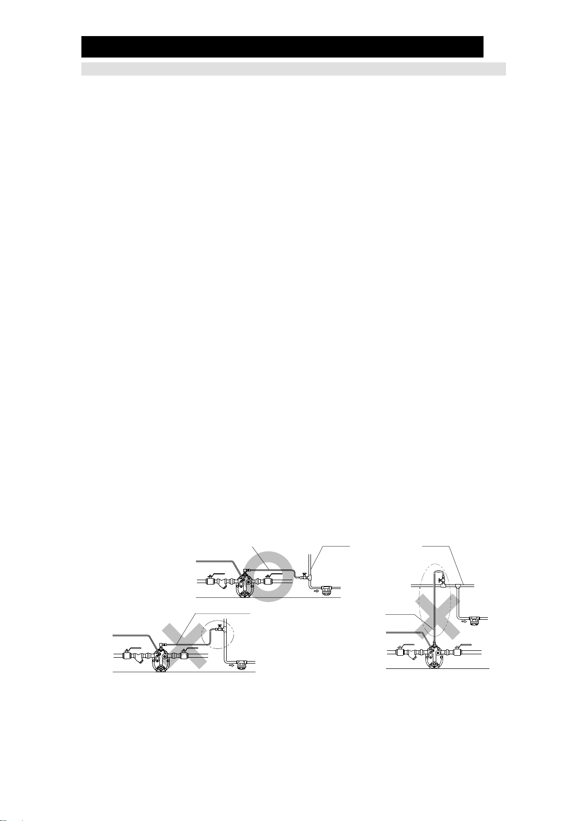
If water hammer due to steam backflow in the condensate recovery
line is expected, the installation of a check valve vertically and as close
as possible to the recovery line is recommended.
When the rise in piping is 30 m (100 ft) or further from the PowerTrap, installation of
a check valve is recommended for the prevention of return water hammer.
Backflow
Water Hammer
Prevention
Check Valve
Backflow
Water Hammer
Prevention
Check Valve
Pi
172-65637MA-05 (GP5C PowerTrap) 8 Jun 2020
10
Installation Procedure
Installation, inspection, maintenance, repairs, disassembly, adjustment and valve
opening/closing should be carried out only by trained maintenance personnel.
(1) Pumped Medium:
Fluids that can be discharged through the PowerTrap are limited to steam
condensate and water. PowerTraps that have been specially constructed for other
specific fluids are not limited by this restriction.
(2) Connecting the piping
When connecting piping to the product, install appropriate piping support to prevent
the piping load from being applied to the product.
If piping load is applied, it may cause damage to threaded parts or leakage may
occur from the sealing part.
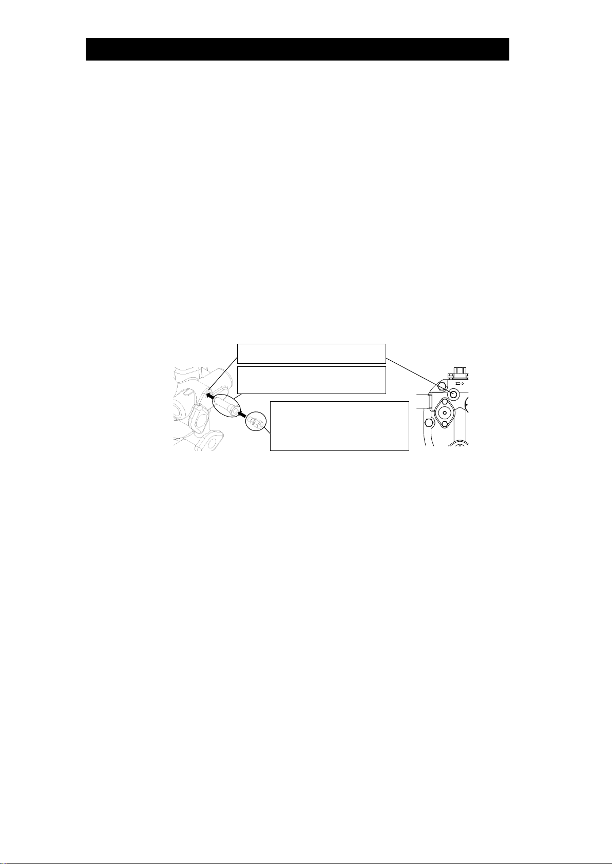
(3) Motive Medium Supply Pipe [Sm1] and Motive Medium Supply Tube [Sm2]:
The diameters of the motive medium supply pipe [Sm1] and of the valve on the
motive medium supply pipe [Vm] diameter should be at least 15 mm (1/2in). If copper
or stainless steel tubes are used for the connection from the motive medium supply
tube [Sm2] to the PowerTrap, make sure that the tubes inner diameter is at least 8
mm (5/16 in) but no more than 3 m (10 ft) in length. The inner diameter of the valve
and tube fittings connecting to the PowerTrapshould also be at least 8 mm (5/16 in).
Install a strainer [Km] (at least 15 mm (1/2in) and 40-mesh or finer) on the
PowerTrap motive medium supply tube [Sm2] as close to the PowerTrap as
possible and install a union joint for maintenance, while allowing sufficient space for
positions for horizontal installations if installed on a horizontal piping.
Only use steam, compressed air or nitrogen as the motive medium.
The maximum motive medium supply pressure is 0.5 MPaG (75 psig, 5 barg).
When the motive medium is steam, install a drip leg on the motive medium supply
pipe [Sm1], and a steam trap [St] on the drip leg. Proper discharge capacity may
not be achieved if condensate accumulates in the motive medium supply pipe
[Sm1] or tube [Sm2]. In addition, rust and scale can cause steam leakage, which
results in the PowerTrap becoming inoperable.
When steam or high temperature air is used as a motive medium, make sure to use
steel pipe for the motive medium supply tube [Sm2].
(4) Pressure Reducing Valve on the Motive Medium Supply Piping:
When the motive medium pressure [Pm] is greater than 0.5 MPaG (75 psig, 5
barg), install a TLV pressure reducing valve (such as the DR20) in order to reduce
the motive medium pressure to the PowerTrap. In order to prevent the pressure
from rising at dead end shut off, be sure to install a relief valve between the
(Piping should be
arranged so
condensate does not
accumulate, limiting
piping length to 3 m
(10 ft))
Motive Medium
Supply Pipe [Sm1]
(Condensate will accumulate if the
piping is installed in a vertical
arrangement. Not recommended
even if the piping length is shorter
than 3 m (10 ft).
Steam Trap [St]
Steam Trap [St]
Motive Medium Supply Tube [Sm2]
Motive Medium Supply Tube [Sm2]
172-65637MA-05 (GP5C PowerTrap) 8 Jun 2020
11
pressure reducing valve and the PowerTrap.
The set pressure of the pressure reducing valve should be equal to or greater than
0.05 MPa (7 psi, 0.5 bar) higher than the back pressure [Pb].
When the pumping capacity of the PowerTrap is insufficient for the set motive
pressure, increase the set pressure even further. However, the set pressure must
not exceed 0.5 MPaG.
(5) Exhaust Pipe/Tube
The exhaust pipe/tube [Se] should be connected to the upper part of the
condensate receiver [Dh]. The exhaust pipe/tube [Se] should be shorter than 3 m,
and with an inner diameter of 8 mm or greater.
Do not remove the exhaust plug installed on the product. This exhaust plug is
needed to achieve proper operation. In the event the exhaust plug has been
removed, wrap the thread part with 3 3.5 turns of sealing tape or apply sealing
compound and tighten it to a torque of 30 N・m (22 lbf・ft).
Connect the exhaust pipe/tube to the exhaust plug (inner diameter of 8 mm (1/4in)).
The pipe/tube can be connected using a commercially-available nipple, street
elbow, ring joint, etc.
When steam or high temperature air is used as a motive medium, make sure to use
the steel pipe for the exhaust pipe/tube [Se].
(6) Inlet and Outlet Piping
Install a condensate inlet pipe [Si] to help condensate flow into the PowerTrap by
gravity. The pipe thickness should be schedule 40 or less for proper operation.
Install a condensate inlet strainer [Ki] (40-mesh or finer) on the PowerTrap pumped
medium inlet pipe and install a union joint for maintenance.
The condensate outlet pipe [So] diameter should be at least 25 mm (1 in).
During pumping operation, the PowerTrap uses the motive medium supply
pressure to push out the condensate from the body. The GP5C can discharge
approximately 1.5 liters (3/8US Gallons) of pumped medium for each discharge
operation. The amount of time required for each discharge operation will be
between 5 and 30 seconds, depending on the back pressure and the motive
medium pressure.
This means that the instantaneous flow through the pumped medium outlet pipe
during the discharge operation is between 170 kg (370 lb) and 1 metric ton (2200
lb) per hour.
Accordingly, flowmeters must not be installed on the condensate outlet pipe [So].
Install a steam flowmeter at the steam-using equipment inlet if necessary.
(7) Valves on the Various Pipes
In order to ensure the proper discharge capacity, use full bore ball valves or gate
valves on the condensate inlet [Vi] and outlet pipes [Vo].
Be sure to install a blowdown valve [Vb]. A bellows sealed valve is recommended,
due to the lack of leakage from the gland and easy flow rate adjustment.
Install union or flanged joints between the valves and the PowerTrap to allow for
Exhaust Plug
(Already installed to the product)
Use commercially-available
nipples
(inner diameter of 8 mm (1/4in))
(Not included in the package)
Exhaust Port
172-65637MA-05 (GP5C PowerTrap) 8 Jun 2020
12
easy maintenance.
Be sure to provide the necessary maintenance space for PowerTrap disassembly
an and Tolerance Angle for Installation
(8) Condensate Receiver [Dh] and Filling Head [A]
Please refer to Receiver.
The size and vent pipe aperture are determined by (a) the amount of flash steam in
the in-flowing condensate (pumped medium) and (b) the amount of pumped
medium held back while the PowerTrap is discharging.
If the receiver is small, the flow of flash steam may cause the condensate to flow
out the vent pipe.
If the vent pipe size is small, the pressure in the receiver will rise, restricting the
pumped medium inflow.
Be sure to select a receiver of the correct size.
The filling head represents the distance from the bottom of the PowerTrap (from
grade) to the bottom of the receiver (shown as [A] in the sketch in Steam System
Example). Filling heads lower than the minimum filling head of 155 mm (6 in) must
not be used.
If venting flash steam to a high area, an overflow pipe must be installed to
discharge condensate to a safe area.
An overflow pipe should be installed at the side of the receiver.
Be sure to install a vent pipe and an overflow pipe. Failure to install an
overflow pipe is dangerous, as condensate may spurt from the vent pipe
and could result in burns and other injuries.
Pipe the vent pipe and the overflow pipe to a safe place such as a pit.
Piping size of the overflow pipe should be the same or larger than
condensate inlet pipe.
CAUTION
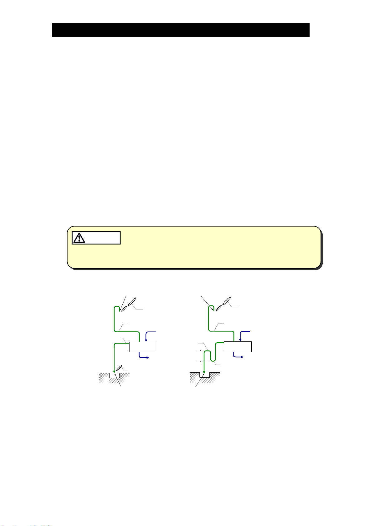
Examples of Overflow Piping for Open Systems
Explanations for overflow piping for open systems
1) If flash steam can be discharged from overflow pipe
Install overflow pipe and vent pipe separately.
2) If flash steam should not be released from overflow pipe (prevent flash
steam release)
Install overflow pipe and vent pipe separately. For overflow pipe, install loop
seal (approx. 300 mm (12 in)). Flash steam release from overflow pipe can be
prevented since water always accumulates at loop seal. Piping size should be
the same or larger than condensate inlet pipe.
(12 in)
Condensate
Receiver
Flash Steam
Flash Steam
Condensate
Receiver
To PowerTrap
Overflow Pipe Overflow Pipe Condensate
Loop Seal
300 mm
(12 in)
1) 2) Flash Steam
Condensate
Receiver
Vent Pipe
Overflow Pipe Overflow Pipe
Condensate
NOTE:
This sketch is forexplanation
purposes only and is not intended
as an installation design.
NOTE:
This sketch is forexplanation
purposes only and is not intended
as an installation design.
Pipe the discharge to a safe place such as a pit.
High temperature steam or hot water may splash.
There is a possibility of condensed hot water dripping from ventpipe
outlet. Make sure to extend to where people do not pass.
Condensate
Receiver
Vent Pipe
Flash Steam
To PowerTrap
Flash Steam

172-65637MA-05 (GP5C PowerTrap) 8 Jun 2020
13
There is a possibility of rust becoming clogged and/or corrosion since
water always present in the loop seal; the possibility is greater if the
piping diameter is too small (generally 25 mm (1 in) or smaller)
Do not install loop seal on the vent pipe
Contact TLV if neither 1) nor 2) above can be installed.

172-65637MA-05 (GP5C PowerTrap) 8 Jun 2020
14
Sizing the Condensate Receiver
When selecting the receiver for the GP5C, select from among the following steps:
(1) Determine the amount of flash steam
(There may be a case that the flash steam hardly
generates when the cold condensate is being pumped):
Amount of flash steam Fs = Q
Fs : amount of flash steam (kg/h) (lb/h)
Qi : amount of condensate (kg/h) (lb/h)
hd: specific enthalpy (kJ/kg) (Btu/lb) of
saturated condensate at condensate inlet set pressure (Pi)
hh: specific enthalpy (kJ/kg) (Btu/lb) of saturated condensate at
condensate receiver set pressure (Ph)
r : specific enthalpy (kJ/kg) (Btu/lb) vaporization (latent heat of steam)
at condensate receiver set pressure (Ph)
(2) Determine the vent pipe diameter according to the amount of flash steam in Vented
Receiver Table - 1 shown on the next page.
(3) Determine the overflow pipe diameter (Dop, refer to the figure below).
NOTE: The overflow pipe diameter should be at least as large as the
condensate inlet pipe diameter (Dcip, refer to the figure below).
(4) Determine the minimum condensate receiver diameter (Dcr, refer to the figure
below) by selecting the largest value among
those from (i), (ii), and (iii) based on a
condensate receiver length of 1 m (3.3 ft).
(i) is the overflow pipe diameter multiplied by 3 or
more.
(ii) is the minimum receiver diameter according to
the amount of flash steam in Vented Receiver
Table - 1 shown on the next page.
(iii) is the minimum receiver diameter according
to the amount of condensate in Vented
Receiver Table - 2 shown on the next page.
NOTE: Receiver length can be reduced by 50% when
the motive pressure (Pm) divided by the back pressure (Pb) is "2" or greater.
(When PmPb2)
ドレンヘッダー
Dop
Overflow
Pipe
Condensate
Receiver
Condensate
Inlet Pipe
Dcr 3 Dop
Dcr
Dcip
Dop Dcip
Receiver
Pi
Ph
Flash Steam
Condensate
Qi
172-65637MA-05 (GP5C PowerTrap) 8 Jun 2020
15
Vented Receiver Table - 1
Flash Steam
up to ~
kg/hour
Receiver
Diameter
mm (in)
(Length: 1 m)
Vent Line
Diameter
mm (in)
Flash Steam
up to ~
lb/hour
Receiver
Diameter
in
(Length: 3.5 ft)
Vent Line
Diameter
in
25
80
(3)
25
(1)
50
3
1
50
100
(4)
50
(2)
100
4
2
75
125
(5)
50
(2)
150
5
2
100
150
(6)
80
(3)
200
6
3
Vented Receiver Table - 2
Amount of
Condensate
kg/hour
Receiver Diameter
mm (in)
(Length: 1 m)
Amount of
Condensate
lb/hour
Receiver Diameter
in
(Length: 3.5 ft)
50 or less
40
(11/2)
100 or less
11/2
100
40
(11/2)
200
11/2
200
40
(11/2)
400
11/2
300
50
(2)
600
2
400
65
(21/2)
800
21/2
500
80
(3)
1000
3
NOTE: When amount of flash steam and condensate are between two values in the table, select
the larger value (one line below).
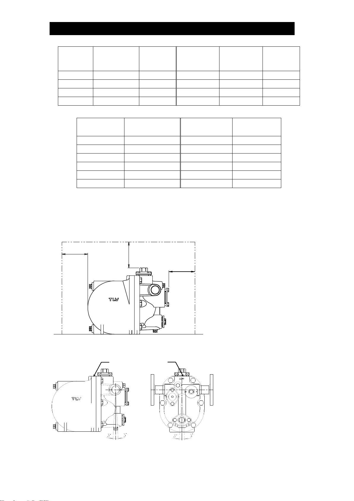
Maintenance Space and Tolerance Angle for Installation
Maintenance Space
The maintenance space shown
in the figure on the left should
be provided to enable
inspection and
disassembly/repair of the GP5C
Unit: mm (in)
Tolerance Angle for Installation
The product should be
inclined no more than 3°
front-to-back and left-to-right.
Ensure the product is
horizontal by checking the
machined surface of the
cover top.
100 (4)
100 (4)
100 (4)
Surface to confirm the
product is horizontal
172-65637MA-05 (GP5C PowerTrap) 8 Jun 2020
16
Operation and Periodic Inspection
After all piping work has been completed in accordance with the
specific piping system designed when the decision to utilize the
PowerTrap was made, check once again to make sure that all pipe
connections have been tightened, gaskets have been inserted where
needed and all parts are securely installed.
At the start-up of operation, large quantities of condensate may flow,
causing the PowerTrap to momentarily overload. Open the inlet valve
gradually so that the condensate flows in slowly.
CAUTION
・Repairs or disassembly of the piping, adjustment and valve opening/
closing should be carried out only by trained maintenance personnel.
・Before connecting piping or disassembling the product, close the inlet
and outlet valves and make every effort to reduce the internal pressure
to cool the product to room temperature.
・When disassembling connecting parts, remove pipes and bolts slowly to
prevent condensate from suddenly flowing out in the event of residual
pressure inside the product.
CAUTION
Install properly and DO NOT use this product outside the recommended
operating pressure, temperature and other specification ranges.
Improper use may result in such hazards as damage to the product or
malfunctions which may lead to serious accidents. Local regulations
may restrict the use of this product to below the conditions quoted.
CAUTION
When disassembling or removing the product, wait until the internal
pressure equals atmospheric pressure and the surface of the product
has cooled to room temperature. Disassembling or removing the
product when it is hot or under pressure may lead to discharge of fluids,
causing burns, other injuries or damage.
CAUTION
Be sure to use only the recommended components when repairing the
product, and NEVER attempt to modify the product in any way. Failure to
observe these precautions may result in damage to the product or burns
or other injury due to malfunction or the discharge of fluids.
CAUTION
Installation, inspection, maintenance, repairs, disassembly, adjustment and valve
opening/closing should be carried out only by trained maintenance personnel.
Operation
(1) Valve Operation
During the first operation after installation, or re-operation after a long shutdown, open
the blowdown valve [Vb] (ensuring the area around the opening is safe) to eliminate
rust and scale completely. Refer to the Steam System Exampledrawings in the
Installationsection to become familiar with the symbols used for the various valves.
If water hammer has occurred, immediately cease operation and close any valves
that are operating.
a) Slowly open the valve [Ve] on the exhaust pipe.
b) Slowly open the valve [Vm] on the motive medium supply pipe. Make sure that there is
no sound of flow from the exhaust pipe/tube [Se] or the condensate inlet pipe [Si].
c) Slowly open the valve [Vo] on the condensate outlet pipe.
d) Slowly open the valve [Vi] on the condensate inlet pipe.
e) The PowerTrap is normal if it operates intermittently during pumping operation; first
exhausting the motive medium to fill with pumped medium, then taking in motive
medium to force the condensate out.
The interval of operation will vary greatly depending on the amount of pumped
medium inflow, the temperature, the motive medium pressure. (The interval of
operation is considered the length of time between the start of one discharge cycle

172-65637MA-05 (GP5C PowerTrap) 8 Jun 2020
17
and the start of the next discharge cycle.)
The relation between the interval of operation Tc(seconds) and the amount of
inflowing pumped medium (Q or Qp) can be roughly determined using the following
formula:
Tc= 5,350/Q Q = 5,350/TcQ: amount of inflowing pumped medium (kg/h)
Tc= 11,888/Qp Qp= 11,888/TcQp: amount of inflowing pumped medium (lb/h)
(2) If an error such as a leak or water hammer occurs after beginning PowerTrap
operation, shut off the valves immediately in the following order:
valve [Vm] on motive medium supply pipe valve [Vi] on condensate inlet valve
valve [Vo] on condensate outlet pipevalve [Ve] on exhaust pipe/tube
(3) Whenever any type of malfunction is suspected in the PowerTrap, refer to the
section.
Periodic Inspection and Diagnosis
There are two types of periodic inspection: visual inspection and disassembly inspection.
(1) Visual Inspection
As a general rule, this inspection should be performed at least once every 3 months.
Check the following items:
a) There should be no leakage from the PowerTrap or from any of the connections.
b) The PowerTrap unit should be operating cyclically without continuous sound in
the motive medium supply pipe or the exhaust pipe during the pumping
operation (equipment side pressure back pressure).
c) Condensate should not accumulate in the steam-using equipment, and the
temperature of the equipment should not be abnormally low.
d) There should not be any abnormal noise (such as water hammer) from the
pumped medium outlet pipe or the condensate recovery line when the
PowerTrap operates.
(2) Disassembly Inspection
.
As a general rule, this inspection should be performed at least once every 2 years.
When inspecting the interior of the unit, check the following items:
a) Make sure the snap-action unit moves up and down smoothly as the float rises
and falls.
b) Make sure the intake/exhaust valves move up and down smoothly.
c) Make sure the float is not damaged and is not filled with water.
d) Make sure all nuts and bolts are properly installed and fastened.
e) Check to make sure that there is no foreign matter sticking to the shafts and
levers of any of the units, and make sure there is no abnormal wear.
When reassembling, be sure to replace the body and cover gaskets with new
gaskets if damaged.
Also, replace any parts that are broken or show serious wear.
.

172-65637MA-05 (GP5C PowerTrap) 8 Jun 2020
18
Disassembly/Reassembly
NEVER apply direct heat to the float. The float may explode due to
increased internal pressure, causing accidents leading to serious injury
or damage to property and equipment.
WARNING
・Repairs or disassembly of the piping, adjustment and valve opening/
closing should be carried out only by trained maintenance personnel.
・Before connecting piping or disassembling the product, close the inlet
and outlet valves and make every effort to reduce the internal pressure
to cool the product to room temperature.
・When disassembling connecting parts, remove pipes and bolts slowly to
prevent condensate from suddenly flowing out in the event of residual
pressure inside the product.
CAUTION
Use hoisting equipment for heavy objects (weighing approximately
20 kg (44 lb) or more). Failure to do so may result in back strain or other
injury if the object should fall.
CAUTION
When disassembling or removing the product, wait until the internal
pressure equals atmospheric pressure and the surface of the product
has cooled to room temperature. Disassembling or removing the
product when it is hot or under pressure may lead to discharge of fluids,
causing burns, other injuries or damage.
CAUTION
Do not use excessive force when connecting threaded pipes to the
product. Over-tightening may cause breakage leading to fluid
discharge, which may cause burns or other injury.
CAUTION
Use the procedures on the following pages to remove components. Use the same
procedures in reverse to reassemble. (Installation, inspection, maintenance, repairs,
disassembly, adjustment and valve opening/closing should be carried out only by trained
maintenance personnel.)
In cases where sufficient maintenance space has been provided for (see
Space and Tolerance Angle for Installation
disconnecting the inlet and outlet piping. Where there is insufficient maintenance space,
first disconnect the inlet and outlet piping, and then move the unit to a spacious area in
which maintenance can be carried out safely.
When reassembling:
Also replace any gaskets, units or parts that are broken or show serious wear. If any
When reassembling, coat threads and bolts with anti-seize. Tighten the body and
cover bolts left and right in a uniform manner, being careful to avoid uneven
tightening.
If drawings or other special documentation were supplied for the product, any torque
given there takes precedence over values shown in this Instruction Manual.
172-65637MA-05 (GP5C PowerTrap) 8 Jun 2020
19
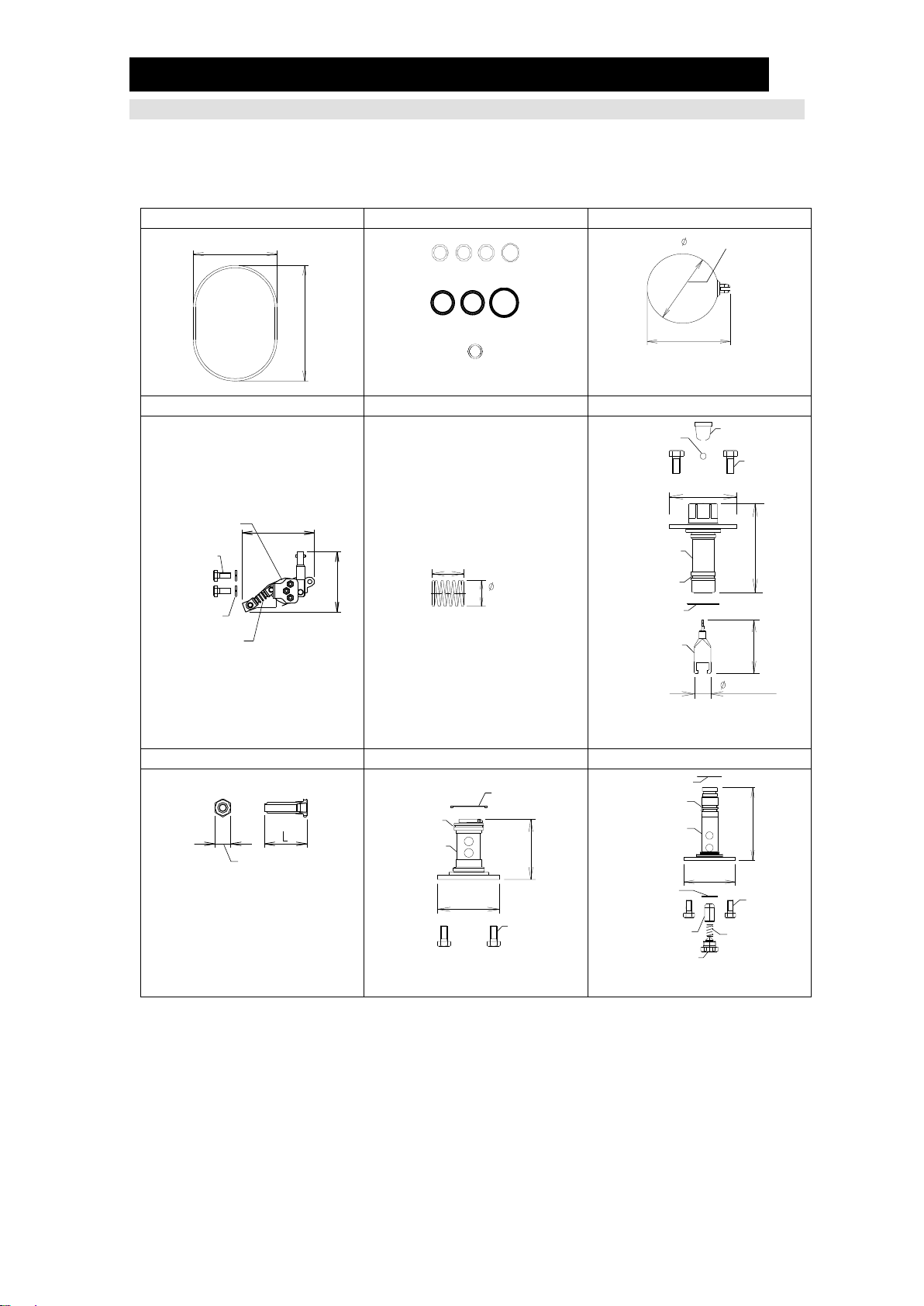
Replacement Parts
The following replacement parts are available from TLV. Parts are not available
individually, only together in kits. (See Configuration)
Dimensions: mm (in)
1. Cover Gasket
2. Seal Set
3. Float
Weight: 0.27 kg (0.59 lb)
4. Snap-action Unit
5. Coil Spring (Snap-action Spring)
6. Intake-Exhaust Valve Unit
Weight: 0.45 kg (0.99 lb)
Weight: 0.33 kg (0.73 lb)
7. Exhaust Plug
8. Inlet Check Valve Unit
9. Outlet Check Valve Unit
For Body Material
FC250 (cast iron): L=51.5 (2)
CF8M (cast stainless steel):
L=56.5 (21/4)
Weight: 0.33 kg (0.73 lb)
Weight: 0.38 kg (0.84 lb)
139 (51/2)
194 (75/8)
O-ring: 4 pcs.
PTFE Gasket: 3 pcs.
Metal Gasket: 1 pc.
100 (315/16)
117 (45/8)
100 (4)
84 (X)
Hex Bolt
Spring
Washer
Snap-action
Unit
Coil Spring
19 (3/4)
11.5
(7/16)
70 (23/4)
90.7 (39/16)
60.8
(23/8)
18.5 (3/4)
Screen
Bolt
Steel Ball
Intake-Exhaust
Valve Seat
O-Ring
Gasket
Intake-Exhaust
Valve
21 (13/16)
Gasket
O-Ring
Inlet
Check Valve
Bolt
70 (23/4)
68.2
(211/16)
99 (37/8)
70 (23/4)
Gasket
O-Ring
Outlet Check
Valve
Gasket Bolt
Valve for Outlet
Check Valve Coil Spring
Holder
Table of contents
Other TLV Industrial Equipment manuals


Popular Industrial Equipment manuals by other brands

Silca
Silca Ilco Orion SMARTY 2000 operating manual

Siemens
Siemens 3TL61 operating instructions

Mönninghoff
Mönninghoff HexaFlex 313. Series Operating and assembly instructions

Danfoss
Danfoss iSave 21 user manual

Roper Whitney
Roper Whitney 816 Installation, operation and maintenance manual

ABB
ABB HT610734 Operation manual


