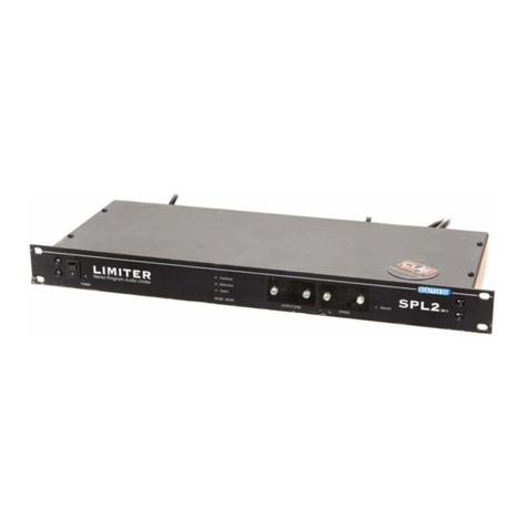
Dateq SPL6 User manual

SPL5_040825_V1.0EN
POWER
RESET ADVAN C ED AU D IO LEVEL REC ORD ER
SAN C T IO NRED UC E OVERLOADD ET EC T
STAT U S C O NT ROL
SPL 6
SPL6
Multiband limiter
&
Sound level recorder
Manual

SPL5_040825_V1.0EN

UK DATEQ SPL6 Manual Safety inst uctions 3
Safety instructions
1. All safety inst uctions, wa nings and ope ating inst uctions must be ead fi st.
2. All wa nings on the equipment must be heeded.
3. The ope ating inst uctions must be followed.
4. Keep the ope ating inst uctions fo futu e efe ence.
5. The equipment may neve be used in the immediate vicinity of wate ; make su e that wate and
damp cannot get into the equipment.
6. The equipment may only be installed o fitted in acco dance with the manufactu e s
ecommendations.
7. The equipment must be installed o fitted such that good ventilation is not obst ucted in any way.
8. The equipment may neve be installed in the immediate vicinity of sou ces of heat, such as pa ts
of heating units, boile s, and othe equipment that gene ates heat (including amplifie s).
9. Connect the equipment to a powe supply of the co ect voltage, using only the cables
ecommended by the manufactu e , as specified in the ope ating inst uctions and/o shown on
the connection side of the equipment.
10.The equipment may only be connected to a legally app oved ea thed mains powe supply.
11.The powe cable o powe co d must be positioned such that it cannot be walked on in no mal
use, and objects that might damage the cable o co d cannot be placed on it o against it. Special
attention must be paid to the point at which the cable is attached to the equipment and whe e the
cable is connected to the powe supply.
12.Ensu e that fo eign objects and liquids cannot get into the equipment.
13.The equipment must be cleaned using the method ecommended by the manufactu e .
14.If the equipment is not being used fo a p olonged pe iod, the powe cable o powe co d should
be disconnected f om the powe supply.
15.In all cases whe e the e is a isk, following an incident, that the equipment could be unsafe, such
as:
●if the powe cable o powe co d has been damaged
●if fo eign objects o liquids (including wate ) have ente ed the equipment
●if the equipment has suffe ed a fall o the casing has been damaged
if a change in the pe fo mance of the equipment is noticed
App op iately qualified technical staff must check it.
16.The use may not ca y out any wo k on the equipment othe than that specified in the ope ating
inst uctions.

Index
Safety inst uctions..............................................3
Int oduction........................................................5
Installation..........................................................6
Connections...................................................6
Signaling connecto ; .................................7
Exte nal display; .......................................8
Mic ophone input.......................................8
Audio inputs..............................................8
Audio outputs............................................8
Exte nal attenuato ....................................9
Signaling...................................................9
Ope ation.........................................................10
Technical specifications...................................11
Inputs...........................................................11
Outputs........................................................11
Common......................................................11
Audio.......................................................11
Limite .....................................................11
Memo y...................................................11
Exte nal connections...............................11
Powe supply ..........................................11
Dimensions and weight...........................11
Int oduction configu ation.................................16
Installation........................................................17
Configu ation...............................................17
Configu ation license........................................19
Unlocking the limite ....................................19
Automatic installation...................................20
Limite configu ation....................................21
Mode.......................................................21
Limite settings........................................21
Ce tification date.....................................21
Mic ophone settings................................21
Sanction settings.....................................21
Multiband.....................................................22
Multiband Limite .....................................22
10 band pa amet ic Equalize .................22
Time slots....................................................23
Bypass calende ......................................23
Display.........................................................24
Logging........................................................25
Remote access............................................26
Telnet......................................................26
FTP.........................................................26
Owne info mation.......................................27
System settings...........................................28
IP settings...............................................28
Language................................................28
Fi mwa e.................................................28
Use settings...........................................29
Logging............................................................30
System status..............................................30
Event log .....................................................31
Upload histo y..............................................31
Sound sample data......................................32
P oduct suppo t................................................35

UK DATEQ SPL6 Manual Int oduction 5
Introduction
The SPL6 is an advanced audio level limite that sto es the sound level samples fo at least twelve
months. The sound level samples can be viewed using the inte nal web pages o exte nally sto ed
th ough automatic email. Othe impo tant data is also sto ed like powe ing up, sanctions o
possible f aud attempts.
Using the web inte face the SPL6 can be ead out and adjusted. The e is no sepa ate platfo m
depended softwa e equi ed. All use s can only view settings and logging. To adjust configu ation
settings an additional passwo d and license file is equi ed. TO connect to the SPL6 a compute o
tablet must be equipped with a netwo k connection. When connected to a netwo k o the Inte net,
the SPL6 can be emotely monito ed.
The SPL6 uses a measu ement mic ophone to dete mine the actual sound level. When
measu ement shows the sound level exceeding the maximum set level, it will educe slowly the full
sound spect um to the maximum allowed level. In multiband mode the SPL6 will slightly educe the
single f equency band befo e adjusting the full spect um.
With the special co elation detection the SPL6 detects exte nal noise pollution and can igno e fo
example applauding o sc eaming audience. This way the maximum sound level is always insu ed.
The special calende functions allow fo diffe ent sound levels du ing the day and yea .
PO W E R
RESET ADVAN C ED AU DI O L EVE L RE CORD ER
SA N C T I ONRE D UC E O V E RLOADD ET E C T
STAT U S C O N T R OL
SPL 6

6Installation DATEQ SPL6 manual UK
Installation
The limite is installed in between the audio sou ce (a mixing desk fo example) and the speake
amplifie .
When calib ating the system, the powe amplifie has to be set to maximum output level. The
limite will educe the signal as much as needed. When used at nominal level the established
sound p essu e limit will not be exceeded afte configu ing the limite . Howeve if in any case this
should happen, e.g. When the mixe is used above the nominal level, the limite will automatically
adjust the signal to ensu e the sound p essu e level emains below the maximum allowed level.
Connections
The SPL6 is equipped with balanced audio in,- and outputs. This type of connection gua antees a
solid sound quality, even when long audio cables a e used. Afte the limite is installed the audio
connecto s a e cove ed to p event late adjustments. Removal of this cove will be egiste ed by
the SPL6. To e-activate the limite the key on the f ont is needed.
Mic ophone input; XLR 3-pin female
Pin Function Description
1 G ound Audio g ound
2 Audio + Supply and audio
3 Audio - Supply and audio
Table 1: mic ophone connections
Audio input left and ight; XLR 3-pin female
Pin Function Description
1 G ound Audio g ound
2 Audio + Audio in phase
3 Audio - Audio out of phase
Table 2: Audio-input connections
Audio outputs left and ight; XLR 3-pin male
Pin Function Description
1 G ound Audio g ound
2 Audio + Audio in phase
3 Audio - Audio out of phase
Table 3: audio-output connections
Image 1: Connecting the SPL6

UK DATEQ SPL6 manual Netwo k installation 7
Signaling connector;
DB-25 female
Pin Function In/ output
1 Exte nal attenuato In
2 Reduction signal Out; 15V/ 5mA max.
3 Ove load signal Out; 15V/ 5mA max.
4 Live OK signal Out; 15V/ 5mA max.
5 Wa ning signal Out; 15V/ 5mA max.
6 Level OK signal Out; 15V/ 5mA max.
7 Safe level signal Out; 15V/ 5mA max.
8 Exte nal VU unit In/ Out
9 Mic ophone + In
10 Left audio in + In
11 Right audio in + In
12 Left audio out + Out
13 Right audio out + Out
14...17 Digital g ound (to be used with the
signaling outputs)
18...20 Analogue g ound (to be used with the
audio in and outputs)
21 Mic ophone - In
22 Left audio in - In
23 Right audio in - In
24 Left audio out - Out
25 Right audio out - Out
Table 4: DB25 connections
USB po t; USB-B female
Pin Function Description
1 VCC + Supply
2 Data – Data
3 Data + Data
4 GND G ound
Table 5: USB connections
Netwo k po t; RJ45 female
Pin Function Description
1 TX-D + Data
2 TX-D – Data
3 RX-D + Data
4 Not in use
5 Not in use
6 RX-D – Data
7 Not in use
8 Not in use
Table 6: Netwo k connections

Installation DATEQ SPL6 manual UK
External display;
Jack 3-pens female
Pin Function Description
SL G ound Data g ound
Tip Data TX Data send
Ring Data RX Data eceive
Table 7: Exte nal display connections
Microphone input
Connect the supplied measu ing mic ophone he e. The wi ing of the mic ophone can be
lengthened with standa d mic ophone cable. Pay attention to the pola ity of the wi ing. If
the mic ophone is w ongly connected it won't wo k. The limite will give an e o message,
and the volume will be ext emely educed.
The mic ophone should be installed so that it 'hea s' both sound f om the speake s as well
as the sound f om the c owd in the oom. The mic ophone can be placed close to the
speake s when the maximum allowed level is ve y low. This educes the effects of
backg ound noises.
Audio inputs
Balanced audio inputs. Pin 1 and 3 of the XLR connecto should be linked togethe when
the mixe only has unbalanced outputs. The mixe s' signal can be connected to pin 2, and
the g ound to pin 1.
Audio outputs
Connect the powe amplifie s he e. Connect pin 2 (signal) and pin 1 (g ound) when the
powe amplifie does not have balanced inputs.

UK DATEQ SPL6 manual Netwo k installation 9
External attenuator
This input can be used to educe the maximum sound p essu e level with an exte nal
potentiomete . The maximum sound p essu e level can be educed by connecting a linea
10kOhm potentiomete between pin1 and pin 14.
This can be useful to educe the sound p essu e level f om behind the ba . It is also
possible to automatically educe the sound p essu e level, fo instance when in the summe
some doo s a e opened.
Signaling
eduction signaling
An indicato to show that the limite has educed the sound p essu e level can be connected to this
output. This output has the same function as the eduction LED on the f ont of the limite (Audio
eduction).
Overload signaling
This output indicates an ove load somewhe e in the limite . This can be the measu ing mic ophone
o the audio input. This output has the same function as the ove load LED on the f ont.
Live OK signaling
This output is active as long as the limite is not in sanction mode. A solid-state elay, to tu n off
the powe supply of the live band, can be connected to this output. If the maximum sound
p essu e level is exceeded by a band, the limite will go into sanction mode and cut off the powe
supply automatically. Afte a p e-set du ation the sanction will be dissolved.
Warning signaling
Level OK
Safe sound pressure
These outputs give an imp ession of the actual sound p essu e level with espect to the maximum
allowed level:
•The wa ning signaling output becomes active, as soon as the maximum sound p essu e level is
exceeded.
•Level OK indicates that the sound p essu e level is below the maximum allowed level, but is
getting close (0...12dB span).
•Safe sound p essu e indicates that the sound p essu e level is well below the maximum allowed
limit (12dB o mo e).
These indicato s can be placed nea the disc-jockey, o the live band, to give them an imp ession
of the sound p essu e level.
External VU unit
This is the data connection with the optional SPL-D2 MKII display. The exte nal display can also
di ectly be connected to the SPL6. Fo this a ste eo 6.3mm jack cable is equi ed.

10 Ope ation DATEQ SPL6 manual UK
Operation
1 2 3 4
1. Key switch:
Afte emoving the cove lid, the key needs to be set to the blue position to eactivate the
limite . Afte eactivating the key needs to be etu ned to the ed position. The key switch also
esets sanction.
2. Display:
The display shows all impo tant values like system time, cu ent sound level in diffe ent values
(dBA, dBC, Leq and peak level) and the cu ent eduction. The display can also show the sound
level histo y, sound spect um, configu ation settings and calib ation date.
3. Status LED's:
•DETECT LED the SPL6 detected audio signal on the line input (-24dB o mo e),
•REDUCE LED shows the audio level is above the set maximum. The SPL6 educes the
output level,
•OVERLOAD LED shows an ove loaded signal p esent at the line o mic ophone input (12dB
above th eshold level),
•SANCTION LED shows the limite in sanction state. On f aud detection the limite will also
go into sanction state. The sanction LED will blink. Reset by time o eset key.
4. Cont ol:
The cont ol knob allows to switch between the diffe ent display views. It also allows to select the
special test mode, that tempo a ily educes the output level. This functionality is specially
designed fo monito ing agencies.
PO W E R
RESET ADVAN C ED AU DI O L EVE L RE CORD ER
SA N C T I ONRE D UC E O V E RLOADD ET E C T
STAT U S C O N T R OL
SPL 6

UK DATEQ SPL6 Manual Technical specifications 11
Technical specifications
Inputs
Mic (Measu ement mic ophone)......................XLR-3 female. Use only the o iginal DCM-5
mic ophone
Line (left and ight)...........................................XLR-3 female. Elect onically balanced.
Maximum input level...............................+18dBu
Input impedance.....................................50kOhm
Commom-mode ejection.......................>86dB
Outputs
Line (left and ight)...........................................XLR-3 male. Elect onically balanced.
Output impedance..................................50Ohm
Common
Audio
F equency esponse...............................5Hz...22kHz @ -1dB
Signal/ noise atio...................................>80dB
THD+N (IEC-A).......................................<0.06%
Limiter
Th eshold................................................70...120dBA ( esolution 1dB)
Output co ection....................................-50...+18dB ( esolution 0,5dB)
Mic ophone co ection............................-40...+18dB ( esolution 0,5dB)
Maximum attenuation adjustment...........-6...-50dB ( esolution 0,5dB)
Memory
4GB SDHC
365 days * sound p essu e info mation ( esolution 1 second)
365 days* event memo y
1GB live eco ding
External connections
Exte nal attenuation................................0...-20dB (10kOhm lin. potentiomete )
Signaling and switching outputs..............24V/ 5mA max.
Power supply
Supply voltage........................................100...240VAC/ 50Hz
Powe usage...........................................15W
Dimensions and weight
F ont.......................................................483mm x 45mm (B x H) = 19inch/ 1HE
Depth......................................................175mm
Weight....................................................2.7kg
*Soundlevel data and event logging are stored for maximal 365 days or less when memory is full. The memory system will delete and override oldest data first.
SPL6_151201_V1.0EN


SPL6
Multiband limiter
&
Sound level recorder
Configuration

Notes

Index
Safety inst uctions..................................................3
Int oduction.............................................................5
Installation...............................................................6
Connections.......................................................6
Signaling connecto ; .....................................7
Exte nal display; ...........................................8
Mic ophone input...........................................8
Audio inputs...................................................8
Audio outputs.................................................8
Exte nal attenuato ........................................9
Signaling........................................................9
Ope ation..............................................................10
Technical specifications........................................11
Inputs...............................................................11
Outputs............................................................11
Common...........................................................11
Audio...........................................................11
Limite ..........................................................11
Memo y........................................................11
Exte nal connections...................................11
Powe supply ..............................................11
Dimensions and weight................................11
Int oduction configu ation.....................................16
Installation.............................................................17
Configu ation....................................................17
Configu ation license............................................19
Unlocking the limite .........................................19
Automatic installation.......................................20
Limite configu ation.........................................21
Mode............................................................21
Limite settings............................................21
Ce tification date..........................................21
Mic ophone settings.....................................21
Sanction settings.........................................21
Multiband..........................................................22
Multiband Limite .........................................22
10 band pa amet ic Equalize ......................22
Time slots.........................................................23
Bypass calende ..........................................23
Display.............................................................24
Logging............................................................25
Remote access................................................26
Telnet..........................................................26
FTP..............................................................26
Owne info mation............................................27
System settings................................................28
IP settings....................................................28
Language.....................................................28
Fi mwa e......................................................28
Use settings................................................29
Logging.................................................................30
System status...................................................30
Event log .........................................................31
Upload histo y..................................................31
Sound sample data..........................................32
P oduct suppo t....................................................35

16 Ope ation DATEQ SPL6 Manual UK
Introduction configuration
The SPL6 is an advanced audio level limite that sto es the sound level samples fo at least twelve
months. The sound level samples can be viewed using the inte nal web pages o exte nally sto ed
th ough automatic email. Othe impo tant data is also sto ed like powe ing up, sanctions o
possible f aud attempts.
Using the web inte face the SPL6 can be ead out and adjusted. The e is no sepa ate platfo m
depended softwa e equi ed. All use s can only view settings and logging. To adjust configu ation
settings an additional passwo d and license file is equi ed. TO connect to the SPL6 a compute o
tablet must be equipped with a netwo k connection. When connected to a netwo k o the Inte net,
the SPL6 can be emotely monito ed.
The SPL6 uses a measu ement mic ophone to dete mine the actual sound level. When
measu ement shows the sound level exceeding the maximum set level, it will educe slowly the full
sound spect um to the maximum allowed level. In multiband mode the SPL6 will slightly educe the
single f equency band befo e adjusting the full spect um.
With the special co elation detection the SPL6 detects exte nal noise pollution and can igno e fo
example applauding o sc eaming audience. This way the maximum sound level is always insu ed.
The special calende functions allow fo diffe ent sound levels du ing the day and yea .
PO W E R
RESET ADVAN C ED AU DI O L EVE L RE CORD ER
SA N C T I ONRE D UC E O V E RLOADD ET E C T
STAT U S C O N T R OL
SPL 6

UK DATEQ SPL6 manual Netwo k installation 17
Installation
The SPL6 configu ation pages a e tested fo use with the following Inte net b owse s:
•Mozilla Fi efox ve sion 36
•Google Ch ome ve sion 40
Due to secu ity isks Mic osoft Inte net Explo e is not suppo ted.
Configuration
In this chapte the configu ation and system settings fo the SPL6 a e explained. These settings
no mally a e made once on installation. All made settings can be sto ed in a backup file fo late
use o esto ing the o iginal settings afte changing.
Connecting the computer
The compute is connected to the limite using an UTP cable. The limite can also be integ ated
into an existing netwo k. Connect the ethe net plug into the netwo k.
Di ectly connected to the compute , a st aight o c oss wi e cable can be connected.
When using a di ect cable connection the compute s IP add ess needs to be manually changed.
Make su e the compute is assigned to the same IP ange.
The limite can now be accessed using: http://spl6/ o by ente ing the default IP add ess:
http://192.168.1.101/. When not using the default IP add ess, like in a custom netwo k
envi onment, the IP add ess can be viewed in the settings view on the f ont panel display.

1 Installation DATEQ SPL6 manual UK
Example settings to connect the SPL6 to the internet
The following images show how a oute is set to edi ect the connections f om the inte net to the
SPL6. The exact settings depend on the b and and type of the oute .
Allowing exte nal access f om the inte net is often called as 'Vi tual se ve s', 'Po t fo wa ding' o
'Po t edi ection'.
•Open the oute configu ation page
•Select the 'NAT setup' page
•Select 'Po t edi ection'
•Now set the IP add ess fo the SPL6, the exte nal po t numbe and the local po t numbe .
The following po ts a e used:
Http: po t 80
FTP: po t 21
Telnet: po t 23
Important:
•Always ask you system administ ato s' pe mission to make these type of adjustments. If you
doubt, o a e not familia with netwo k settings, ask you netwo k administ ato fo assistance!
•Some inte net se vice p ovide s do not allow thei clients to add se ve s to the inte net. Please
check you cont act o info m with you ISP.
•You connection to the inte net needs to have a static IP add ess to make the SPL6 available
ove the inte net. Some p ovide s use dynamic IP add esses. This means you IP add ess can
change afte some time. This makes it impossible to connect to the SPL6.
•Opening a po t to the inte net is always a secu ity isk, the efo e check fo updates egula ly,
and do not make the limite available on the inte net is not eally needed.

UK DATEQ SPL6 configu ation manual Configu ation 19
Configuration license
The configu ation pages a e commonly only used to view settings and sound sample logging. Fo
viewing o expo ting no license o passwo d is needed. Changing settings, including fi st
installation an installe license and passwo d is needed.
The installe license is only g anted to ce tified p ofessional audio installe s. When you own an
SPL limite and settings need to be changed, you need to contact you local dist ibuto o installe .
The closest supplie can be found at the Dateq selling points pa t of the website: www.dateq.nl.
An installe license is linked and egiste ed to the installing company and can not be t ansfe ed to
thi d pa ties. The installe license contains all company and contact details, that will be sto ed into
the SPL limite du ing configu ation.
Unlocking the limiter
Befo e changes can be made the license passwo d must be ente ed. This
passwo d is linked and sto ed within the license file. When accessing the limite
th ough the inte net an ext a use name and passwo d can be needed. The
inte net use name and passwo d a e handled in the emote access section.
Only afte co ectly ente ing the inte net use name, passwo d, uploading the license file and
ente ing the license passwo d, configu ation changes can be made.

20 Configu ation DATEQ SPL6 Configu ation manual UK
Automatic installation
Th ough the automatic installation p ocess the basic sound level settings fo
the SPL6 can be made. On sta ting the installation the diffe ent popup
windows will guide the installation.
Make su e popup blocke s in you b owse a e disabled befo e sta ting.
The limite will automatically set all audio values du ing the installation p ocess. Befo e sta ting the
complete audio system must be connected and powe ed on. It is best to use an audio-sou ce with
less dynamics to pe fo m the installation; this makes it easie fo the compute to calculate the
levels. Select the menu-item 'Automatic install'. The softwa e will pe fo m a step-by-step
installation:
•Set the output-level to nominal. This means that all the g een LEDs on the VU-mete light up,
and eve y now and then some ed light will blink,
•Set the output level of the amplifie s to the maximum,
•Ente the maximum dB values,
•The limite will adjust the output-volume, until the equested sound level is acqui ed. In the
meantime ead the sound level at the level-mete in the oom,
•Afte some time the actual audio-level in the oom will be asked. This is to compensate the
mic ophone offset value.
The limite is now calib ated. Check the settings by aising the volume of the mixe till the
'REDUCE' LED on the f ont panel lights up. The limite will automatically lowe the volume.
All the settings can be changed manually, if necessa y.
Table of contents
Other Dateq Microcontroller manuals
Popular Microcontroller manuals by other brands
Texas Instruments
Texas Instruments TMS320C67 DSP Series Programmer's reference guide
GAI-Tronics
GAI-Tronics 12562-109 Installation kit
LAPIS Semiconductor
LAPIS Semiconductor ML610Q421 user manual
Synaptics
Synaptics AudioSmart manual

BECKWITH ELECTRIC
BECKWITH ELECTRIC M-2601 Instruction book
NXP Semiconductors
NXP Semiconductors Freescale K22 Reference manual
Espressif Systems
Espressif Systems ESP32-H2 Series Hardware Design Guidelines
Texas Instruments
Texas Instruments Chipcon CC2430 manual
STMicroelectronics
STMicroelectronics X-NUCLEO-IHM07M1 user manual

Broadcom
Broadcom WICED Smart quick start guide

Renesas
Renesas V853 user manual
InPlay
InPlay NanoBeacon IN100 user manual
