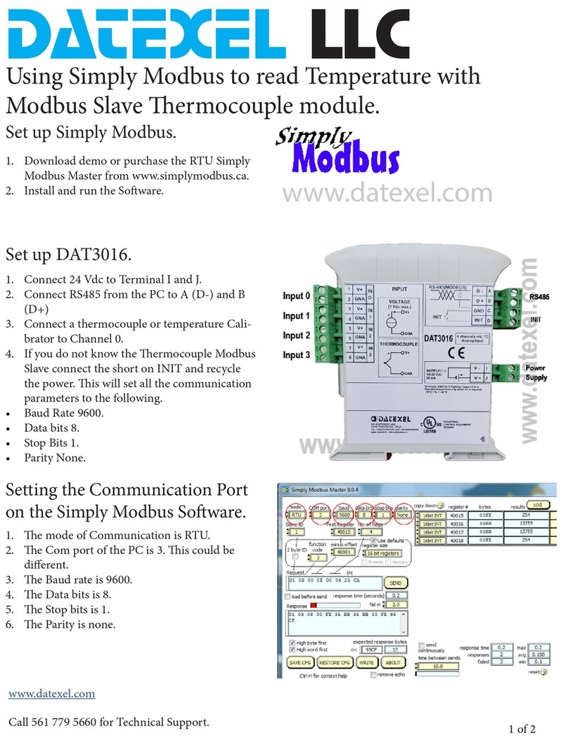
Datex-Ohmeda M-NMT Use and care manual

Datex-Ohmeda
S/5TM NeuroMuscular Transmission Module, M-NMT (Rev. 02)
Technical Reference Manual Slot
All specifications are subject to change without notice.
Document No. 800 1018-1
June 2001
Datex-Ohmeda Inc.
3030 Ohmeda Drive
53707-7550 MADISON, WIS
USA
Tel. +1-608-221 1551, Fax +1-608-222 9147
www.us.datex-ohmeda.com
Datex-Ohmeda Division,
Instrumentarium Corp.
P.O. Box 900, FIN-00031
DATEX-OHMEDA, FINLAND
Tel. +358 10 394 11 Fax +358 9 146 3310
www.datex-ohmeda.com
Instrumentarium Corp. All rights reserved.


Table of contents
Document No. 800 1018-1
i
TABLE OF CONTENTS
NeuroMuscular Transmission Module, M-NMT
TABLE OF CONTENTS i
TABLE OF FIGURES ii
Introduction 1
1 Specifications 2
1.1 General specifications ..............................................................................................................................2
1.2 Technical specifications............................................................................................................................2
1.2.1 NMT.................................................................................................................................................2
1.2.2 Stimulator........................................................................................................................................2
1.2.3 Regional block mode........................................................................................................................2
2 Functional description 3
2.1 Measurement principle .............................................................................................................................3
2.1.1 Nerve stimulation .............................................................................................................................3
2.1.2 Response.........................................................................................................................................4
2.1.3 Regional block .................................................................................................................................4
2.2 Main components.....................................................................................................................................4
2.2.1 NMT board .......................................................................................................................................4
2.3 Connectors and signals.............................................................................................................................6
2.3.1 Module bus connector......................................................................................................................6
2.3.2 Front panel connector.......................................................................................................................7
3 Service procedures 8
3.1 General service information.......................................................................................................................8
3.2 Service check ...........................................................................................................................................9
3.2.1 Recommended tools ........................................................................................................................9
3.3 Disassembly and reassembly..................................................................................................................13
4 Troubleshooting 14
4.1 Troubleshooting chart .............................................................................................................................14
4.2 Troubleshooting flowchart .......................................................................................................................15
5ServiceMenu 16
5.1 NMT menu..............................................................................................................................................17
6 Spare parts 19
6.1 Spare part list.........................................................................................................................................19
6.1.1 NMT Module, M-NMT rev. 00...........................................................................................................19
6.1.2 NMT Module, M-NMT rev. 01...........................................................................................................19
6.1.3 NMT Module, M-NMT rev. 02...........................................................................................................19
6.1.4 Front panel stickers for AS/3 modules (square buttons) ...................................................................20
6.1.5 Front panel stickers for S/5 modules (round buttons).......................................................................20
7 Earlier revisions 21
APPENDIX A 23

Datex-Ohmeda S/5 monitors
Document No. 800 1018-1
ii
Service check form A-1
TABLE OF FIGURES
Figure 1 NeuroMuscular Transmission Module, M-NMT ....................................................................................... 1
Figure 2 Principle of response measurement ...................................................................................................... 4
Figure 3 Serial communication and opto isolation............................................................................................... 5
Figure 4 Stimulator block diagram...................................................................................................................... 5
Figure 5 Module troubleshooting flowchart .......................................................................................................15

NeuroMuscular Transmission Module, M-NMT
Document No. 800 1018-1
1
INTRODUCTION
This section provides information for the maintenance and service of the NeuroMuscular
Transmission Module, M-NMT. The M-NMT module is a single width plug-in module designed for
use with the S/5 Anesthesia and Compact Anesthesia Monitors. The module contains peripheral
nerve stimulation and response measurement which supports electromyography EMG. The module
can also be used as a nerve locator for regional nerve blocking with a regional block cable.
However, in this case there is no response measurement.
Figure 1 NeuroMuscular Transmission Module, M-NMT

Datex-Ohmeda S/5 monitors
Document No. 800 1018-1
2
1SPECIFICATIONS
1.1 General specifications
Module size, W ×D ×H 37 ×180 ×112 mm / 1.5 ×7.1 ×4.4 in
Module weight 0.37 kg /0.8 lbs
Power consumption 3.3 W
1.2 Technical specifications
1.2.1 NMT
Stimulation modes Train of four (TOF)
Double burst (3.3) (DBS)
Single twitch (ST)
50 Hz tetanus + post tetanic count (PTC)
Measurement intervals for TOF and DBS
Manual; 10 s, 12 s, 15 s, 20 s, 1 min, 5 min, 15 min
Measurement intervals for ST Manual; 1 s, 10 s, 20 s
1.2.2 Stimulator
Stimulus pulse Square wave, constant current
Pulse width 100, 200 or 300 µs
Stimulus current range 10...70 mA with 5 mA steps
Stimulus current accuracy 10 % or ±3 mA whichever is the greater
Max. load 3 kΩ
Max. voltage 300 V
1.2.3 Regional block mode
Stimulation modes Single twitch
Intervals 1 s, 2 s, 3 s
Stimulus pulse Square wave, constant current
Pulse width 40 µs
Stimulus current range 0...5.0 mA with 0.1 mA steps
Stimulus current accuracy 20 % or 0.3 mA whichever is the greater

NeuroMuscular Transmission Module, M-NMT
Document No. 800 1018-1
3
2FUNCTIONAL DESCRIPTION
2.1 Measurement principle
2.1.1 Nerve stimulation
There are three stimulus modes in the NeuroMuscular Transmission Module: Train of Four (TOF),
Double Burst 3,3 (DBS) and Single Twitch (ST).
In the Train of Four stimulus mode, four stimulation pulses are generated at 0.5 second intervals.
The response is measured after each stimulus and the ratio of the fourth and first response of the
TOF sequence is calculated (TOF%).
NOTE: If the first response does not exceed a certain signal level, TOF% is not calculated due to
poor accuracy.
Double burst (3,3) stimulation includes two bursts with a 750 ms interval. Both bursts consist of
three pulses separated by 20 ms intervals. The responses of both bursts are measured, and the
ratio of the second and first response is calculated (DBS%). EMG responses are measured
immediately after the first stimulus pulse of both bursts.
In Single Twitch stimulation, one stimulation pulse is generated. The response is measured after
the stimulus. In order to prevent decurarization of the stimulated area, the measurement is
automatically stopped after 5 minutes stimulation in 1 sec cycle time.
Tetanic/PTC
Tetanic/PTC (Post Tetanic Count) can measure deeper relaxation than TOF. The tetanic stimulation
is produced when Start is chosen under Tetanic/PTC. The length of stimulation is 5 seconds. The
stimulation generates pulses with a frequency of 50 Hz and with a selected pulse width and
current. After tetanic stimulation and a three second delay, Single Twitch stimulation is produced
to detect the post tetanic count (PTC). PTC describes the number of responses detected after
tetanic stimulation. If there is no response, the measurement will be stopped. If responses will not
fade away, a maximum of 20 responses will be calculated. If more can be detected, the PTC value
is displayed only as '> 20' and measurement will be stopped. If the TOF, DBS or ST measurement
cycle was on when tetanic stimulation started, the cycle will continue after the PTC. After
completing the PTC measurement during 1 minute TOF, DBS or another PTC measurement is not
possible. This is to avoid erroneous readings due to post tetanic potentiation.

Datex-Ohmeda S/5 monitors
Document No. 800 1018-1
4
2.1.2 Response
Before each stimulation, the sequence offset, noise and threshold for the response detection is
measured. Offset is a baseline of the noise measurement. Noise is calculated by the same
algorithm as the response signal itself. The response detection threshold is calculated based on
the noise, and if the response is not greater than the threshold then it is interpreted as no response.
EMG
Mechano
Sensor
Measurement
EMG leads off
Timing control
A
/D & P
µ
Figure 2 Principle of response measurement
EMG measurement
The EMG response is measured as integrated muscle activity. The EMG measurement starts 3 ms
after the stimulation and lasts 15 ms. The 3 ms delay helps to prevent the effect of stimulation
artifact.
Mechano sensor measurement
Response is measured as movement of the thumb, which is the area of positive signal.
2.1.3 Regional block
A regional block cable can be used as a nerve locator in local anesthesia. A maximum current of
5.0 mA is given every, every other or every 3rd second. The response measurement is ocular.
2.2 Main components
2.2.1 NMT board
The NMT Circuit Board consists of the following functional sections:
•constant current stimulator
•measuring electronics for the EMG signals

NeuroMuscular Transmission Module, M-NMT
Document No. 800 1018-1
5
•microprocessor for the stimulation and measuring control, and for counting the measuring
results
•serial communication
The serial bus speed is 500 kbps and the bus itself is half duplex, i.e. data can be transferred in
both directions but only one way at a time.
Serial communication
Figure 3 Serial communication and opto isolation
Stimulator
The constant current stimulator generates pulses whose amplitude is independent of the load. The
main components of the stimulator are a transformer, a capacitor and a transistor. The transformer
produces a high voltage which charges the capacitor and the transistor adjusts the pulse width and
amplitude of the current.
Patient Constant current
generator
Power supply
Current
adjustment
Current
control
Continuous
stimulation
congestion
80C196KD
PWM
HSO
Figure 4 Stimulator block diagram

Datex-Ohmeda S/5 monitors
Document No. 800 1018-1
6
2.3 Connectors and signals
2.3.1 Module bus connector
13
1
14
25
Table 1 Module bus connector (X1)
Pin No. I/O Signal
1 I RESET_RS485
2 I -15 VDC
3 I +15 VDIRTY
4 I +15 VDC
5 I/O -DATA_RS485
6 I/O DATA_RS485
7 - Ground & Shield
8 I -RESET_RS485
9 I CTSB
10 O RTSB
11 I RXDB
12 O TXDB
13 - Ground & Shield
14 I +32 VDIRTY
15 I GroundDIRTY
16 I CTSC
17 O RTSC
18 I RXDC
19 O TXDC
20 - ON/STANDBY
21 - PWM_ECG
22 - RXDD_RS232
23 - TXDD_RS232
24 I +5 VDC
25 I +5 VDC

NeuroMuscular Transmission Module, M-NMT
Document No. 800 1018-1
7
2.3.2 Front panel connector
NMT connector (NMT)
Pin No. Signal
6
8
9
0
1
2
4
5
7
3
1
2
3
4
5
6
7
8
9
10
EMG Signal +
EMG Signal -
Not Used
Stimulus +
Stimulus -
Ground
Not Connected
Sensor Identification
+5 V
Mechanical Signal

Datex-Ohmeda S/5 monitors
Document No. 800 1018-1
8
3SERVICE PROCEDURES
3.1 General service information
Field service of the NeuroMuscular Transmission Module, M-NMT, is limited to replacing faulty
circuit boards or mechanical parts. Faulty circuit boards should be returned to Datex-Ohmeda for
repair.
Datex-Ohmeda is always available for service advice. Please provide the unit serial number, full
type designation, and a detailed description of the fault.
The Datex-Ohmeda NMT Stimulator (order code 871251) is recommended for functional checks.
CAUTION Only trained personnel with appropriate equipment should perform the tests and repairs outlined in
this section. Unauthorized service may void warranty of the unit.

NeuroMuscular Transmission Module, M-NMT
Document No. 800 1018-1
9
3.2 Service check
These instructions include complete procedures for a service check. The service check is
recommended to be performed after any service repair. However, the service check procedures can
also be used for determining possible failures.
The procedures should be performed in ascending order.
The instructions include a check form (Appendix A) which should be filled in when performing the
procedures.
The mark ?in the instructions means that the check form should be signed after performing
the procedure.
The procedures are designed for monitors with S/5 monitor software of revision 01. However, most
of the procedures also apply to monitors, which contain some other monitor software
type/revision.
3.2.1 Recommended tools
Tool Order No. Notes
NMT simulator 871251
M-NMT ElectroSensor
M-NMT MechanoSensor
M-NMT Sensor Cable
3 kΩresistor
Screwdriver
•Detach the module box by removing the two screws from the back of the module. Be careful
with the loose latch and spring locking pin.
1. Check internal parts:
−screws are tightened properly
−cables are connected properly
−the EMC cover is attached properly
−there are no loose objects inside the module
?
2. Check external parts:
−the front cover and the front panel sticker are intact
−connectors are intact and are attached properly
−the module box, latch and spring locking pin are intact
?
•Refit the module box and check that the latch moves properly.

Datex-Ohmeda S/5 monitors
Document No. 800 1018-1
10
•Turn the monitor on and wait until the normal monitoring screen appears.
•Configure the monitor screen so that information regarding the NMT measurement is shown,
for example:
Monitor Setup - Screen 1 Setup - Digit Fields - Field 4 - Nmt
•Preset the NMT measurement settings:
Others - NMT - Stimulus Mode - TOF
Set Cycle Time - 10 sec
NMT Setup - Current - S(70 mA)
Pulse Width - 200
µ
µµ
µ
S
Stim. Beep Volume - 2
3. Plug in the module. Check that it goes in smoothly and locks up properly
?
4. Check that the module is recognized, i.e. the NMT header with related information appear in
the chosen digit field.
?
5. Enter the service menu:
Monitor Setup - Install/Service (password 16-4-34) - Service (password 26-23-8)
Take down the information regarding NMT software by selecting SCROLL VERS and turning
the ComWheel.
?
6. Enter the NMT module service menu:
Parameters - NMT
Check that the “Timeouts”, “Bad checksums” and “Bad c-s by mod” values are not increasing
faster than by 50 per second. Check that the module’s memories have passed the internal
memory test, i.e. “RAM”, “ROM” and “EEPROM” all state OK.
?
7. Check the front panel START-UP and STOP/CONTINUE membrane keys.
Press each key for at least one second and check that the key being pressed is identified,
i.e. the color under the corresponding text on the menu turns blue.
?

NeuroMuscular Transmission Module, M-NMT
Document No. 800 1018-1
11
8. Check that the message “Cable off” is shown in the digit field and that “Cable” in the service
menu states OFF.
Plug the M-NMT Sensor Cable with the M-NMT ElectroSensor into front panel connector
NMT. Check that the message in the digit field changes to “Measurement OFF” and “Cable”
on the service menu states EMG and ELECTR. OFF.
?
9. Perform the stimulus current test.
Connect a 3 kΩresistor between the ElectroSensor’s stimulus electrode leads (brown and
white).
Start the test by highlighting START CURR. TEST on the service menu and pressing the
ComWheel. Check that the test was successful with all three test currents, i.e. the “Current
test (mA):” on the menu states 30 OK, 50 OK and 70 OK.
?
•Connect the M-NMT ElectroSensor leads to the NMT simulator. Set the switch on the
simulator to “Fade off” and turn the knob to “max”. Check “Cable” on the service menu now
states only EMG.
10. Start NMT measurement (TOF) by pressing the START-UP key on the module.
When the message “Supramax search” changes to “Setting reference” in the digit field,
check that the supramaximal current detected is less than 70 mA, i.e. the “Current set”
value on the service menu is less than 700.
?
11. Check that the module gives four successive stimulus pulses with 10 second intervals. A
small asterisk (✼) should be shown in the digit field during each of the stimulus pulses and
simultaneous sound signals should be heard from the loudspeaker.
Check that on the service menu the values for “T1%”, “T2%”, “T3%”, “T4%” and “Ratio%”
are all within 950-1059.
Check also that in the digit field the “TOF%” value is within 95-105, “Count” is 4 and “T1%”
is within 95-105.
?
12. Check that the “Noise” value on the service menu stays under 50.
?
13. Change the stimulus pulse width to 100 µs through the NMT service menu:
NMT Setup - Pulse Width - 100
µ
µµ
µ
S

Datex-Ohmeda S/5 monitors
Document No. 800 1018-1
12
Check that the “TOF%” value is still within 95-105, “Count” is 4 and “T1%” is within 95-105
in the digit field.
Check the same parameters with a stimulus pulse width of 300 µs.
?
14. Turn the knob on the NMT simulator to “0”.
Check that on the service menu the values for “T1%”, “T2%”, “T3%”, “T4%” turn to 0 and the
“Ratio%” states - - -. In the digit field “TOF%” should also state - - - , and “Count” and “T1%”
should show 0.
Turn the NMT simulator knob back to “max”.
?
15. Change the stimulus mode to Double Burst Stimulation (DBS) through the service menu:
NMT Setup - Stimulus Mode - DBS
Check that the module now gives only two stimulus pulses with a 10 seconds interval.
Check that on the service menu the values for “T1%”, “T2%”, and “Ratio%” are still within
950-1059. In the digit field the “DBS%” value should be within 95-105, “Count” is 2 and
“T1%” is within 95-105.
?
16. Change the stimulus mode to Single Twitch Stimulation (ST):
NMT Setup - Stimulus Mode - ST
Check that the module starts to give only one stimulus pulse with a 1 second interval. Note
the time when the ST stimulation started.
Check that on the service menu the value for “T1%” is within 950-1059. In the digit field the
“Count” value should be 1 and “T1%” within 95-105.
Let the monitor continue to give single twitch stimulation.
?
17. Check that the NMT measurement stops and the message “Measurement OFF” appears in
the digit field for NMT five minutes after the start of the ST stimulation.
?
18. Replace the M-NMT ElectroSensor with the M-NMT MechanoSensor and check that “Cable”
on the service menu states PIEZO.
?

NeuroMuscular Transmission Module, M-NMT
Document No. 800 1018-1
13
19. Perform an electrical safety check and a leakage current test.
?
20. Check that the module functions normally after performing the electrical safety check.
?
21. Clean the module with suitable detergent.
?
•Fill in all necessary documents.
3.3 Disassembly and reassembly
Disassemble the NeuroMuscular Transmission Module, M-NMT, in the following way. See the
exploded view of the module.
1. Remove the two screws from the back of the module.
2. Pull the module box slowly rearward and detach it from main body. Be careful with the loose
latch and spring locking pin.
3. Detach the NMT board by removing the two screws located near the front panel frame,
disconnect the cables and pull out the front panel frame.
To reassemble the module, reverse the order of the disassembly steps.
CAUTION When reassembling the module, make sure that the cables are reconnected
properly.

Datex-Ohmeda S/5 monitors
Document No. 800 1018-1
14
4TROUBLESHOOTING
4.1 Troubleshooting chart
Trouble Cause Treatment
Check the stimulus electrodes.
EMG electrode off.
Loose electrodes or loose stimulus
clip.
Change or attach the electrodes or
clip.
Supramax. not found. Loose electrodes or loose stimulus
clip.
Stimulus electrodes attached to
wrong place.
Patient is relaxated.
Change or attach the electrodes or
clip.
Change the place of the stimulus
electrode.
Response too weak. Loose stimulus electrodes.
Measuring electrodes attached to
wrong place.
Patient is relaxated.
Change or attach the electrodes.
Change the place of the meas.
electrodes.
Ref. not stable. Patient is relaxated.
Movement artifact.

NeuroMuscular Transmission Module, M-NMT
Document No. 800 1018-1
15
4.2 Troubleshooting flowchart
no
Possible fault in NMT module
Open NMT Service Menu
Check Timeouts, Bad checksums,
Bad c-s by mod
Check RAM,ROM,EEPROM
Check that sensor is identified
Connect ElectroSensor to NMT
stimulator and start measurement
Check front panel key functions
Fault not in NMT module
Replace the original sensor Connect the connector Replace the original
NMT input board
Replace the original sensor
Replace the original NMT input
board
Replace the original sensor
Replace the original NMT sensor
cable
Replace the original NMT input
board
Replace the original keypad
Connect the keypad
Replace the original NMT sensor
cable
Replace the original
NMT sensor cable
Does another module
work in the same slot?
Does the test pass with
another sensor?
Does the test pass with
another NMT sensor
cable?
Are the NMT input board
wires connected?
Does the test pass
with another NMT
input board?
Does the test pass with
another sensor?
Does the test pass with
another NMT sensor
cable?
Does the test pass with
another sensor?
Does the test pass with
another NMT input
board?
Does the test pass with
another NMT sensor
cable
Does the test pass with
another NMT input
board?
Is the keypad
connected?
Does the test pass with
another keypad?
Test stimulus current
OK? Replace NMT board
no
yes
yes
OK?
OK?
yes
yes
yes yes no yes
no
OK?
Responses OK?
OK?
yes
yes
yes
yes
yes
yes
yes
no
yes
no
no
no
no
yes
no
no
no
no
no
yes
no
no yesno
no
no
Replace NMT board
Replace NMT board
Replace NMT board
Replace NMT board
Replace NMT board
Figure 5 Module troubleshooting flowchart

Datex-Ohmeda S/5 monitors
Document No. 800 1018-1
16
5SERVICE MENU
1. Press the Monitor Setup key.
2. Select Install/Service (password 16-4-34).
3. Select Service (password 26-23-8).
4. Select Parameters.
5. Select NMT.
Table of contents
Other Datex-Ohmeda Control Unit manuals
Popular Control Unit manuals by other brands
Acromag
Acromag VPX6860 user manual

Dixon Bayco
Dixon Bayco 3020 Series Installation & operating instructions
Quantum Rehab
Quantum Rehab Network Adapter Dynamic DX Basic operation instructions
MFB
MFB SYNTH LITE II Operator's manual
Badger Meter
Badger Meter BadgerTouch HREBT manual
Automationdirect.com
Automationdirect.com Productivity 1000 P1-08TD2 manual
