Datex-Ohmeda S/5 G-AO Product manual

Datex-Ohmeda
S/5TM AirwayModule,G-AO(rev.06)
S/5TM AirwayModule,G-AiO(rev.05)
S/5TM AirwayModule,G-AiOV(rev.04)
S/5TM AirwayModule,G-AOV(rev.04)
S/5TM GasInterfaceBoard,B-GAS(rev.01)
TechnicalReferenceManualSlot
Allspecificationsaresubjecttochangewithoutnotice.
DocumentNo. 8001005-1
June2001
Datex-OhmedaInc.
3030OhmedaDrive
53707-7550MADISON,WIS
USA
Tel.+1-608-2211551,Fax+1-608-2229147
www.us.datex-ohmeda.com
Datex-OhmedaDivision,
InstrumentariumCorp.
P.O.Box900,FIN-00031
DATEX-OHMEDA,FINLAND
Tel.+3581039411Fax+35891463310
www.datex-ohmeda.com
InstrumentariumCorp.Allrightsreserved.


Tableofcontents
DocumentNo. 8001005-1i
TABLEOFCONTENTS
S/5Airwaymodules and S/5 Gas Interface Board,B-GAS
TABLEOF CONTENTS i
TABLEOF FIGURES iii
INTRODUCTION 1
1 Specifications 2
1.1 Generalspecifications..............................................................................................................................2
1.2 Typicalperformance .................................................................................................................................2
1.2.1 CO2..................................................................................................................................................2
1.2.2 Respirationrate................................................................................................................................2
1.2.3 O2....................................................................................................................................................2
1.2.4 N2O .................................................................................................................................................2
1.2.5 Hal,Iso,Enf......................................................................................................................................2
1.2.6 Sev..................................................................................................................................................2
1.2.7 Des..................................................................................................................................................3
1.2.8 Agentidentification..........................................................................................................................3
1.2.9 PatientSpirometry............................................................................................................................3
1.2.10 AirwayPressure(Paw)...................................................................................................................3
1.2.11 TidalVolume(TV)..........................................................................................................................3
1.2.12 MinuteVolume(MV).....................................................................................................................3
1.2.13 Airwayflow...................................................................................................................................3
1.3 Technicalspecification .............................................................................................................................4
1.3.1 CO2..................................................................................................................................................4
1.3.2 O2....................................................................................................................................................4
1.3.3 N2O .................................................................................................................................................4
1.3.4 AA ...................................................................................................................................................4
2 FunctionalDescription 5
2.1 Measurementprinciple.............................................................................................................................5
2.1.1 CO2,N2OandAgentmeasurement....................................................................................................5
2.1.2 O2measurement..............................................................................................................................6
2.1.3 Agentidentification..........................................................................................................................7
2.1.4 PatientSpirometry............................................................................................................................8
2.2 Maincomponents.....................................................................................................................................9
2.2.1 Gassamplingsystem......................................................................................................................10
2.2.2 ACX-200measuringunit.................................................................................................................16
2.2.3 OMmeasuringunit.........................................................................................................................17
2.2.4 ACXmeasuringboard.....................................................................................................................18
2.2.5 ASXagentidentificationbench........................................................................................................20
2.2.6 ASXmeasuringboard.....................................................................................................................20
2.2.7 PVXboard......................................................................................................................................22
2.2.8 Gasmotherboard...........................................................................................................................24
2.2.9 Gasinterfaceboard........................................................................................................................26
2.3 Connectorsandsignals...........................................................................................................................26
2.3.1 Modulebusconnector....................................................................................................................26

Datex-OhmedaS/5AnesthesiaMonitor
DocumentNo.8001005-1
ii
2.3.2 Gasmotherboardconnectors.........................................................................................................27
3 ServiceProcedures 31
3.1 Generalserviceinformation....................................................................................................................31
3.2 Servicecheck.........................................................................................................................................32
3.2.1 Recommendedtools......................................................................................................................32
3.2.2 Recommendedparts......................................................................................................................32
3.3 Disassemblyandreassembly..................................................................................................................41
3.4 Adjustmentsandcalibrations..................................................................................................................42
3.4.1 Gassamplingsystemadjustment...................................................................................................42
3.4.2 Flowratemeasurement..................................................................................................................42
3.4.3 Oxygenmeasurementunitadjustments...........................................................................................44
3.4.4 Flowcalibration..............................................................................................................................46
4 Troubleshooting 47
4.1 Troubleshootingchart.............................................................................................................................47
4.1.1 Supplyvoltagetroubleshooting.......................................................................................................48
4.2 Gassamplingsystemtroubleshooting.....................................................................................................49
4.2.1 Samplingsystemleaktest..............................................................................................................49
4.2.2 Waterseparation............................................................................................................................49
4.2.3 Steamtestforthespecialtubes......................................................................................................49
4.3 OMmeasuringunittroubleshooting.........................................................................................................50
4.4 ACXtroubleshooting...............................................................................................................................50
4.4.1 CleaningthemeasuringchamberofACXmeasuringunit..................................................................50
4.5 ASXagentidentificationunittroubleshooting...........................................................................................52
4.6 PVXboardtroubleshooting......................................................................................................................53
4.7 Gasmotherboardtroubleshooting..........................................................................................................53
4.7.1 InstructionsafterreplacingthesoftwareorGasmotherboard...........................................................53
4.8 Errormessages.......................................................................................................................................54
5Servicemenu 55
5.1 Gasmotherboard...................................................................................................................................56
5.2 ACXservicemenu...................................................................................................................................59
5.3 PVXservicemenu...................................................................................................................................61
5.3.1 Flowcalibration..............................................................................................................................62
5.3.2 Temp&Humservicemenu.............................................................................................................63
5.4 ASXservicemenu...................................................................................................................................64
6 Spareparts 65
6.1 Sparepartslist.......................................................................................................................................65
6.1.1 G-AOrev.01,G-AiOrev.00............................................................................................................65
6.1.2 G-AOrev.02,G-AiOrev.01,G-AOVrev.00,G-AiOVrev.00.............................................................66
6.1.3 G-AOrev.03,G-AiOrev.02,G-AOVrev.01,G-AiOVrev.01.............................................................66
6.1.4 G-AOrev.04,G-AiOrev.03,G-AOVrev.02,G-AiOVrev.02,G-Orev.00,G-OVrev.00 .....................67
6.1.5 G-AOrev.05,G-AiOrev.04,G-AOVrev.03,G-AiOVrev.03,G-Orev.01,G-OVrev.01 .....................67
6.1.6 S/5G-AOrev.06,G-AiOrev.05,G-AOVrev.04,G-AiOVrev.04 ......................................................67
6.1.7 Panelstickers ................................................................................................................................67
6.1.8 S/5panel stickers .........................................................................................................................68
6.1.9 PlannedMaintenance(PM)Kits:.....................................................................................................69
6.1.10 GasInterfaceBoard,B-GAS .......................................................................................................69
7 EarlierRevisions 70

Tableofcontents
DocumentNo. 8001005-1
iii
APPENDIXA
71
ServicecheckFORM A-1
TABLEOFFIGURES
Figure1 CO2/N2O/AAgasabsorptionspectra.....................................................................................................5
Figure2 O2measurementprinciple ....................................................................................................................6
Figure3 AnaestheticAgentsgasabsorptionspectra............................................................................................7
Figure4 Airwaymodule blockdiagram ...............................................................................................................9
Figure5 Gassamplingsystemblockdiagram ...................................................................................................12
Figure6 Gassamplingsystemlayout................................................................................................................13
Figure7 Gassamplingsystemblockdiagram ...................................................................................................13
Figure8 Gassamplingsystemlayout................................................................................................................14
Figure9 ACXphotometer(ACX-200measuringunit)..........................................................................................16
Figure10 CO2/N2O/AAmeasurementblockdiagram......................................................................................17
Figure11 ACXmeasuringboardblockdiagram...............................................................................................19
Figure12 ASXmeasuringunit ........................................................................................................................20
Figure13 ASXmeasuringboardblockdiagram...............................................................................................21
Figure14 PVXboardblockdiagram................................................................................................................23
Figure15 Gasmotherboardblockdiagram....................................................................................................25
Figure16 Gassamplingsystemadjustmentchart...........................................................................................43
Figure17 O2measuringunitadjustments.......................................................................................................46
Figure18 ASXtroubleshootingflowchart.........................................................................................................52
Figure19 PVXboardtroubleshootingflowchart...............................................................................................53

Datex-OhmedaS/5AnesthesiaMonitor
DocumentNo.8001005-1
iv

S/5Airwaymodules
DocumentNo.8001005-1
1
INTRODUCTION
TheS/5AirwayModules,G-AO,G-AiO,G-AOVandG-AiOVaredesignedforusewiththeS/5
AnesthesiaMonitorandprovideairwayandrespiratory parameters.Laterinthismanualmodules
canbecalledw/osystemnameS/5.
ThisTechnicalReferenceManualSlotprovidesinformationforthemaintenanceandserviceofthe
airwaymodules.Pleaseseealsorelated
TechnicalReferenceManual
forinformationrelatedto
systeme.g.relateddocumentation,conventionsused,symbolsonequipment,safetyprecautions,
systemdescription,systeminstallation,interfacing,functionalcheckandplannedmaintenance.
Lettersinthename standfor:
G=Sidemountablegasmodule
O=CO2,PatientO2,andN2O
V=PatientSpirometry
A=Anestheticagents
i=Agentidentification
Table1 OptionsofParameter Modules
CO2N2O PatientO2Agents Agentid Spirometry
G-AO •• • •
G-AiO •• • • •
G-AOV •• • • •
G-AiOV •• • • • •
NOTE:TheAirwayModulesandCompactAirwayModulescannotbeusedsimultaneouslyinthe
samemonitor.
GasInterfaceBoard
GasInterfaceBoard,B-GASisusedforconnectingthe airwaymoduletothecentralunit.The
connectioncanalsobemadethroughtheInterfaceBoard,B-INT.

Datex-OhmedaS/5AnesthesiaMonitor
DocumentNo.8001005-1
2
1SPECIFICATIONS
1.1 Generalspecifications
Modulesize,W×D×H 135×410×135mm/5.3×15.0×5.3in
Moduleweight 6kg/13lbs.
1.2 Typical performance
Samplingrate 200ml/minnominal(180...220ml/min)
Displayupdaterate breath-by-breath
Automaticcompensationforpressure,CO2-N2O,andCO2-O2collisionbroadeningeffect.
Warm-uptime3minforoperation,30minforfullspecifications.
Auto-zeroingisperformedatstart-up,after5min+5min+5min+15min+15min+15min,
andafterthatevery60minatregularintervals.
1.2.1 CO2
Measurementrange 0to10%,(0to10kPa),(0to76mmHg)
Extendedrange 10to15%,(10to15kPa),(76to114mmHg)(unspecified)
IfCO2concentrationisbelow0.1%,0.0%isdisplayed.
1.2.2 Respirationrate
Breathdetection 1% changeinCO2level
Measurementrange 4to60breaths/min
1.2.3 O2
Measurementrange 0to100%O2
1.2.4 N2O
Measurementrange 0to100%N2O
1.2.5 Hal,Iso,Enf
Measurementrange 0to5%
Extendedrange 5to15%(unspecified)
1.2.6 Sev
Measurementrange 0to8%
Extendedrange 8to15%(unspecified)

S/5Airwaymodules
DocumentNo.8001005-1
3
1.2.7 Des
Measurementrange 0to18%
Extendedrange 18to30%(unspecified)
Resolution twodecimalswhentheAAconcentrationbelow 1.0%
IfAAconcentrationisbelow0.10%,0.00%isdisplayed.
1.2.8 Agentidentification
Identifiedagents HAL,ENF,ISO,SEV,DES
Identificationtime 30seconds(typicalvaluewithpureagents)
Identificationthreshold 0.15vol%(typical)
Mixturewarningwhenminorcomponentconcentration>0.3vol%and>15%oftotalagent
concentration
1.2.9 PatientSpirometry
Valuesarevalidwhen:
Respiratoryrate adult4...30 pedi4...50breaths/min
I:Eratio 1:3- 1:0.5
InnerdiameterofETtubeis≥5.5mm(adult)or3to6mm(pediatric).
1.2.10 AirwayPressure(Paw)
Accuracy ±1.5cmH2O
Resolution 1cmH2O
Measuringrange -20to+80cmH2O
1.2.11 TidalVolume(TV)
Accuracy ±6%or30ml(adult);±6%or4ml(ped)
Resolution 1ml
Measurementrange 150to2000ml(adult)
15to300ml(ped)
1.2.12 MinuteVolume(MV)
Resolution 0.1l/min
Measurementrange 2to15l/min(adult)
0.5to5l/min(ped)
1.2.13 Airwayflow
Measurementrange 1.5to100l/minforbothdirections(adult)
0.25to25l/minforbothdirections(ped)

Datex-OhmedaS/5AnesthesiaMonitor
DocumentNo.8001005-1
4
1.3 Technicalspecification
1.3.1 CO2
Measurementrisetime <360ms(from10to90%)
Gainstability ≤0.2%CO2/24h(0to8%)
≤0.4%CO2/24h(8to10%)
Gaintemperaturedrift ≤0.2%CO2/10°C(0to8%)
≤0.4%CO2/10°C(8to10%)
Nonlinearityerror ≤0.2%CO2(0to8%)
≤0.4%CO2(8to10%)
1.3.2 O2
Measurementrisetime <480ms(from10to90%)
Gaindrift ≤2%O2/24h
Gaintemperaturedrift ≤3%O2/10°C
Nonlinearityerror ≤2%O2
1.3.3 N2O
Measurementrisetime <360ms(from10to90%)
Gaindrift ≤2%N2O/24h
Gaintemperaturedrift ≤3%N2O/10°C
Nonlinearityerror ≤2%N2O
1.3.4 AA
Measurementrisetime <520ms(from10to90%)
Gaindrift ≤0.4%AA/24h
Gaintemperaturedrift ≤0.4%AA/10°C
Nonlinearityerror ≤0.2%AA
Protectionagainstelectricalshock
TypeBF

S/5Airwaymodules
DocumentNo.8001005-1
5
2FUNCTIONALDESCRIPTION
2.1 Measurementprinciple
2.1.1 CO2,N2Oand Agentmeasurement
TheCO2,N2O,andanestheticagentgasmeasurementsarebasedonabsorptionofinfraredlightas
itpassesthroughthegassampleinmeasuringchamberinthephotometer.Thelightabsorptionis
measuredatthreewavelengthsusinganinfrareddetector.Oneofthewavelengthsisthatofthe
CO2absorptionpeakat4.3micrometers,thesecondisthatoftheN2Oabsorptionpeakat3.9
micrometers,andthethirdisthatoftheanestheticagentabsorptionpeakat3.3micrometers.The
signalprocessingelectronicsreceivethesignalsfromtheIRdetectoranddemodulateittogetDC
componentsoutofthesesignalswhichcorrespondtothecontentofeachgasinthesample.
Figure1 CO2/N2O/AAgasabsorptionspectra
Datex-OhmedaS/5AnesthesiaMonitor
DocumentNo.8001005-1
6
2.1.2 O2measurement
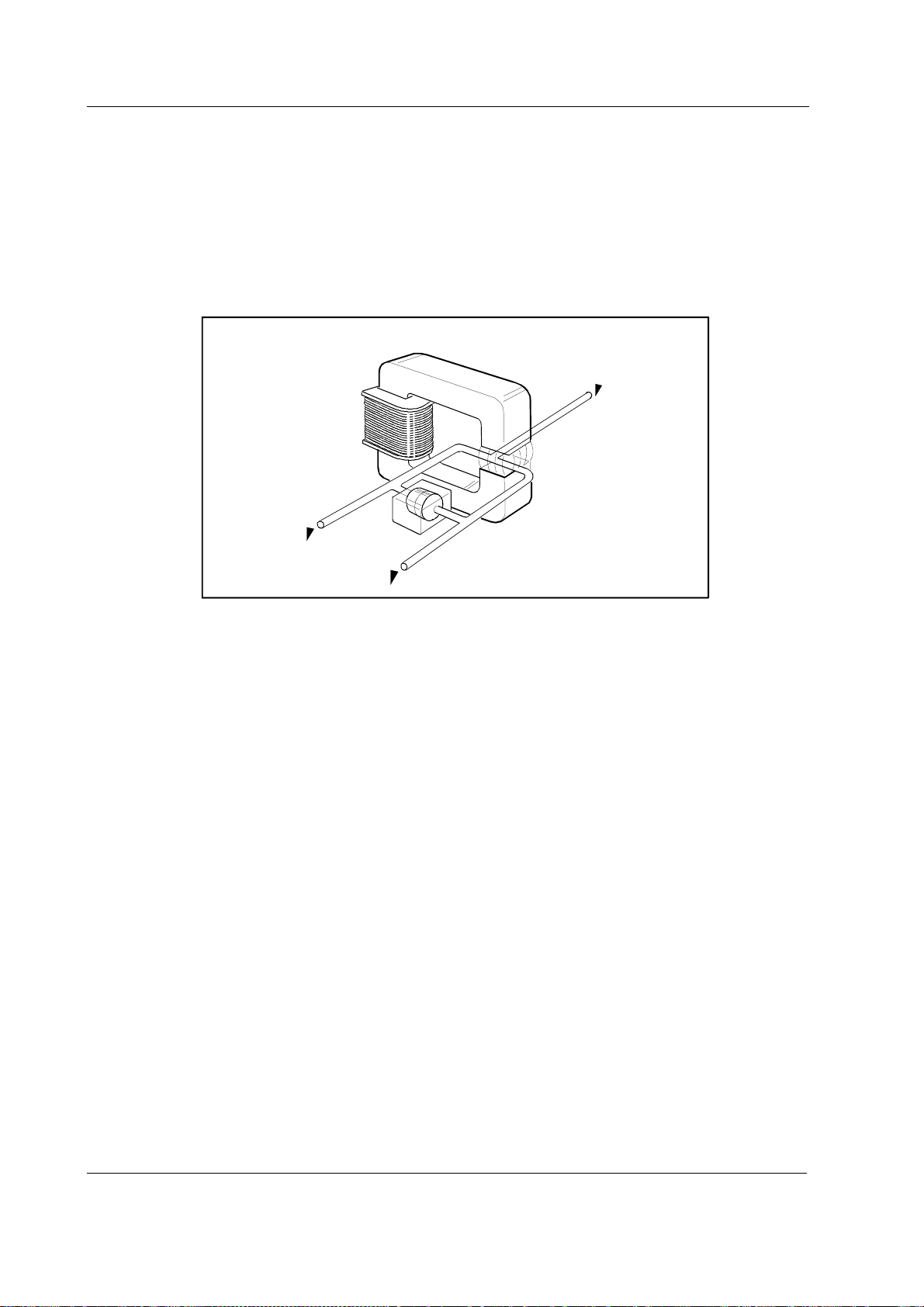
Thedifferentialoxygenmeasuringunitusestheparamagneticprincipleinapneumaticbridge
configuration.Thesignalpickedupwithadifferentialpressuretransducerisgeneratedina
measuringcellwithastrongmagneticfieldthatisswitchedonandoffatafrequencyof110Hz.
TheoutputsignalisaDCvoltageproportionaltotheO2concentrationdifferencebetweenthetwo
gasestobemeasured.
Switched
magnetic
field
Mixture
out
Electromagnet
Microphone
Sample in
Reference in
Figure2 O2measurement principle
S/5Airwaymodules
DocumentNo.8001005-1
7
2.1.3 Agentidentification
TheanestheticagentidentificationbenchidentifiesHalothane,Enflurane,Isoflurane,Desflurane
andSevoflurane.
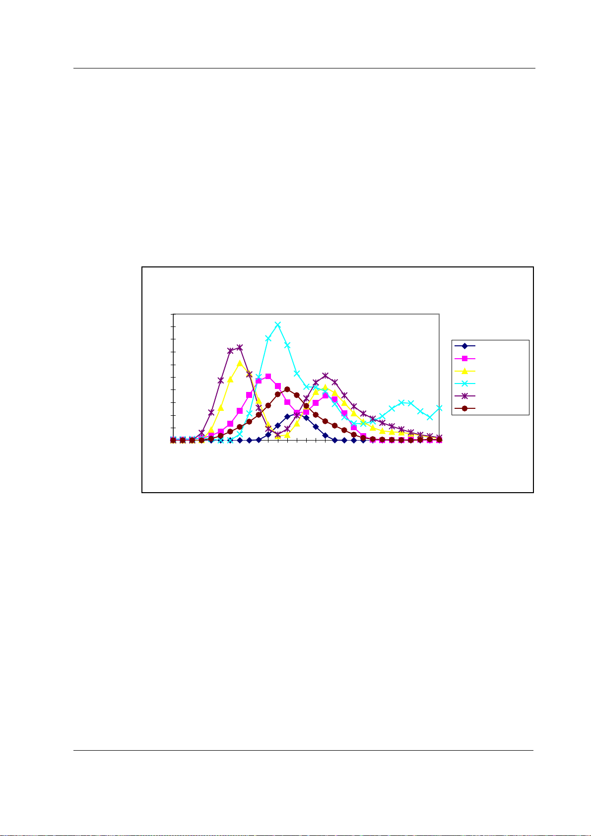
Thebenchmeasuresthespectrumofthegasbetween3.24µmand3.39µm.Because the
spectrumofeachoftheanaestheticagentsisdifferentitispossibletoidentifythem.
Thebenchconsistsofaninfraredsource,ameasuringchamber,arotatingfilterandadetector.The
peakwavelengthofthenarrowbandpassfilterchangeswhentheanglebetweenthelightpathand
thefilterischanged.Whenthefilterrotatesthe requiredspectrumisscannedthrough.Theagentor
amixtureofagentsisidentifiedbycomparingthemeasuredspectrumwithstoredreference
spectra.
Anesthetic Agent Gas Absorption Spectra
0
50
100
150
200
250
300
350
400
450
500
3246
3306
3386
Wavelength [nm]
Halothane 0
Enflurane 0
Isoflurane 0
Sevoflurane 0
Desflurane 0
Freon 0
Figure3 Anaesthetic Agents gas absorption spectra

Datex-OhmedaS/5AnesthesiaMonitor
DocumentNo.8001005-1
8
2.1.4 PatientSpirometry
Inanesthesia,CMV(ControlledMechanicalVentilation)isthemostly usedventilationmode.Inthis
mode,mechanicalbreathsaredeliveredtothepatientby aventilatorwithapropertidalvolume
(TV),respirationrate(RR),andinspiration/expirationratiointime(I:E)determinedbythe settingsof
theventilator.
Deliveryoflifesupportgasesisbasedonpressure.However,withoutknowingvolumemeasuredof
exhalation,onecannotbe surethatabreathoccurred.Theultimategoalofventilationistousethe
leastamountofpressuretogeneratethemostappropriatevolumeforeachbreath.
ThePatientSpirometry monitorsventilationinanesthesia.Bothpatientbreathingcircuitandthe
functionoftheventilatorare monitored.Thefollowingparametersaredisplayed:
Expiratoryandinspiratorytidalvolume(TV)inml.
Expiratoryandinspiratoryminutevolume(MV)inl/min.
Expiratoryvolumeinfirstsecond(V1.0)inpercentforadultsandin0.5secondsforchildren.
Inspiration/expirationratiointime(I:E)
Airwaypressures:Peakpressure(Ppeak),Endinspiratorypressure(Pplat),Positiveendexpiratory
pressure(PEEP),Realtimeairwaypressurewaveform(Paw)
Flow:Realtimeflowwaveform(V')
Compliance(C)
Pressurevolumeloop
Flowvolumeloop
Airwaypressure
PEEP,Ppeak,andPplat aremeasuredbypressuretransduceronthePVXboard.Atmosphericpressure
isusedasareferenceinmeasurement.Thepressuremeasurementismadefromtheairwaypart
thatisclosesttothepatientbetweenpatientcircuitandintubationtube.
Airwayflow
Themeasurementisbasedonmeasuringthekinetic gaspressureandisperformedusingPitot
effect.PressuretransducerisusedtomeasurethePitotpressure.Theobtainedpressuresignalis
linearizedandcorrectedaccordingtothedensityofthegas.Speedoftheflowiscalculatedfrom
thesepressurevaluesandTVvalueisthenintegrated.MVvalueisfurthercalculatedandaveraged
usingTVandRR(respiratoryrate)values.
S/5Airwaymodules
DocumentNo.8001005-1
9
PatientSpirometry sensor,D-lite
PatientSpirometryismeasuredwithaspecificsensor,D-liteorPedi-lite.
D-liteandPedi-litesensorsaredesignedtomeasurekineticpressurebytwo-sidedPitottube.The
pressurereductioncausedbymeasuringcrossistakenintoaccount,too,especiallyinsmallflows.
VelocityiscalculatedfrompressuredifferenceaccordingtoBernoulli'sequation.Flowisthen
determinedusingthecalculatedvelocity.
v= 2dP×
ρ
(fromBernoulli'sequation)
F=v A×,
where,
F=flow(l/min)
v=velocity(m/s)
A=crossarea(m2)
dP=pressuredifference(cmH2O)
ρ=density(kg/m3)
Finallythevolumeinformationisobtainedbyintegratingtheflowsignal.
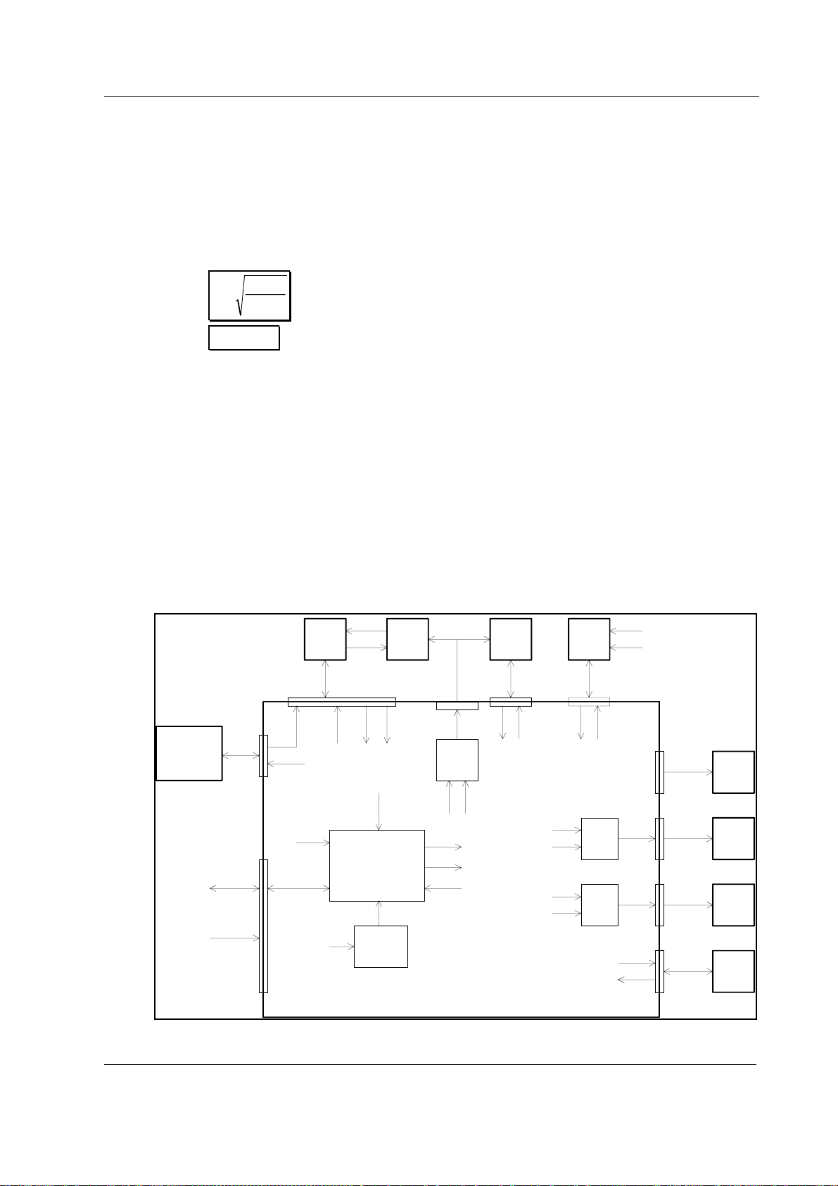
2.2 Maincomponents
Theairway modulesconsistofACX-200andOM-101gasmeasuringunits,ASX-200agent
identificationunit(G-AiO/AiOV),PVXboard(G-OV/AiOV/AOV),gassamplingsystem,ACX
measuringboardandgasmotherboard.
Oxygen
Measuing
Unit
X2
X4
X8
X9
X1
X5
X10
X12
X7
X11
Module
Key
Pump
Valves
Fan
Regulator
Gas Module CPU
Lamp
Driver
Valve
Driver
Pump
Driver
ACX
Board ACX
Bench
ASX
Unit
O2
signal
Lamp
Supply
Voltage
+24/+32 VD
Valve controls
+15 VD, GNDD +15 VD
Pump control
+15 VD, GNDD +15 VD
Mod key in
+15 V
+5 Vref
Serial I/O Serial I/O
+5 V
+5 VL
+15 VD
+/-15 V
+24 /+32 VD
GND
GNDD
Supply
voltages
Valve
controls
ACX
serial
I/O
Supply
voltages
Supply
voltages,
Control
Signal out
Lamp
control
+5 VL
GND
GNDD
Supply
voltages
ASX
serial
i/O
Gas Mother Board
+5 V, GND
ACX, ASX,
PVX serial
I/O
Lamp
control
Pump control
Mod key in
GND
X3
Supply
voltages
PVX
serial
i/O
PVX
Board Gas pressure
and flow in
X1 X1
Figure4 Airway module block diagram

Datex-OhmedaS/5AnesthesiaMonitor
DocumentNo.8001005-1
10
2.2.1 Gassampling system
Thegassamplingsystemsamplesthemeasuredairtothemodule,andremoveswaterand
impuritiesfromit.Asamplinglineisconnectedtothewatertraponthefrontpanel.Thepump
drawsgasthroughthesamplinglinetogasmeasuringunits.Afterthemeasurements,thegasis
exhaustedfromsamplegasoutconnectorontherearpanelofthemodule.
Watertrap, D-fend
Thegassampleentersthe monitorthroughthewatertrap,whereitisdividedintotwoflows,main
flowandsideflow(seeGassamplingsystemblockdiagram).The mainflowgoesintothe
measuringsystemthroughahydrophobicfilter.
Thesideflowcreatesaslightsub-atmosphericpressurewithinthewatertrapcontainer.This
facilitatesgatheringthefluidremovedbythehydrophobicfilter.
Samplingline
Thesamplinglineisanintegralpartofthetotalsamplingsystem.Theresistanceestablishedbythe
samplinglineissignificantwhenthesoftwaredeterminestheocclusionandair-leakalarmlimits
duringtheturn-onsequence.
Thesmallinnerdiametercausesfluidssuchasbloodormucusnottopropagatewithinthe tube,so
thatwhenthelineisclogged,itisreplaced.
TheNafionTM tube 1)
Anafiontube(tubesAorB,andC:seefigure5)isusedtobalancethesample gashumiditywith
thatofambientair.Thetubewillpreventerrorscausedbytheeffectofwatervaporongaspartial
pressurewhenhumidgasesaremeasuredaftercalibrationwithdrygases.Itisinsertedbetween
thewatertrapandthezerovalve(G-AiO/AiOV)orbetweenthezerovalveandACX-200measuring
unit(G-O/OV/AO/AOV).ThetubeisalsoinsertedbetweentheCO2absorberandthezerovalve.
Zerovalve
ThemainflowpassesthroughasolenoidvalvebeforeproceedingtotheACX-200measuringunit.
ThisvalveisactivatedtoestablishthezeropointsfortheACX-200andO2measuringunitsatstart-
up,at5minutes,andafterthatatregularintervals.After1-hourmonitoring,theauto-zeroingis
performedonceanhour.Whenthevalveisactivated,roomairisdrawnthroughtheCO2absorber
intotheinternalsystemandthegassensors.
1) NafionisatrademarkofDuPont

S/5Airwaymodules
DocumentNo.8001005-1
11
Gasmeasuringunits,ACX-200andO2unit
Afterthezerovalve,thegaspassesthroughtheACX-200andO2measuringunits.IntheACX-200
measuringunit,infraredlightispassedthroughchamberscontainingthemainflowgas
(measurement)andachambercontainingreferencegas.Themeasurementismadeby
determiningtheratiobetweenthetwolightintensities.
Theoxygensensorhastwoinputs.Oneinputacceptsthe mainflowandtheotherdrawsinroomair
forreference.Thesensorusesadifferentialpressuretransducertocomparethepressuregradient
producedwhenbothgasesareexposedtoanoscillatingmagneticfield.Bothgasflowsexitfroma
singleport.
Inimodel,theASXagentidentificationunitisinstalledinparallelwiththeoxygensensor.Thetask
ofthe ASXunitistoidentifyanesthesiaagentsbyinfraredlightmethodusedalsointheACX-200
unit.
Pressurevalve
ThepressurevalveisusedtomeasurethepressuregradientbetweentheO2measurementflow
andthe O2referenceflow.Thispressure gradientreflectstheconditionoftheD-fendwatertrap
filter.
Normally thepressure gradientbetweentheO2measurementflowandthereferenceflowis
approximately+8mmHg.Ifthesoftwaredetectsthegradienttobebetween0and-5mmHg,the
pressurevalvewillinitiatepressuremeasurementofthereferenceflow.Ifthegradientisgreater
than-5mmHg,thesoftwaretriggersthemessage’ReplaceTrap’.
Flowcassettes
Theinternal flowratesaresetusingflowcassettes.Thesecassettesare usedtosetthesideflow
rateandtheO2referenceflowrate,theflowratesthroughthemeasuringunitsandthetotalflow
rateofthesamplingsystem.
Samplingpumpanddampingchamber
Thesamplingpumpisavibratingmembranepumpdrivenbya50Hz/12V/0.4Asquarewave
current.
Thedampingchamberisusedtoevenoutthe pulsatingflowandsilencetheexhaustflow.
Datex-OhmedaS/5AnesthesiaMonitor
DocumentNo.8001005-1
12
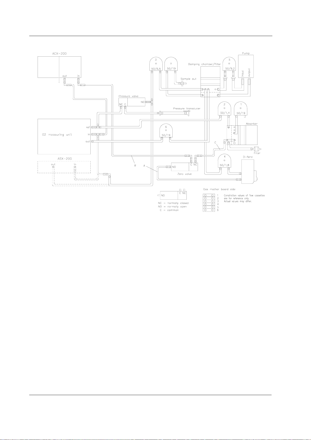
Figure5 Gas sampling system blockdiagram
InG-AO,-AOVmodels,tubeAisTeflon,BandCNafion.InG-AiO,-AiOVmodels,tubesAandCare
Nafion,BisTeflon.
Seenewtubingsinceautumn1998infigure7.

S/5Airwaymodules
DocumentNo.8001005-1
13
Figure6 Gassamplingsystemlayout
Seenewsamplingsystemlayoutsinceautumn1998infigure8.
Filter
CO2
absorber
D-fend
ACX-200
Zerovalve
Pressurevalve
O2sensor
ASX-200
Damping
chamber
Samplepump
RefIN
RoomAIR
Sample
GasIN
Pressure
transducer Sample
GasOUT
A
B
C
sideflow
mainflow
Constrictioncassette
inG-AiO/AiOV
Figure7 Gas sampling system blockdiagram
InG-AO,-AOVmodels,tubeAisTeflon,BandCNafion.InG-AiO,-AiOVmodels,tubesAandCare
Nafion,B isTeflon.Figure7isvalidformodulesmanufacturedsinceautumn1998.
Datex-OhmedaS/5AnesthesiaMonitor
DocumentNo.8001005-1
14
Figure8 Gassamplingsystemlayout
Figure8isvalidformodulesmanufacturedsinceautumn1998.
This manual suits for next models
4
Table of contents
Other Datex-Ohmeda Control Unit manuals


Popular Control Unit manuals by other brands

ECHOMAX
ECHOMAX RTE Installation and operation

Acuity Brands Lighting
Acuity Brands Lighting 5BPMW LED installation instructions

Laird
Laird MSD50NBT user guide

Caleffi solar
Caleffi solar 2522HP Series Installation, commissioning and servicing instructions

CALEFFI
CALEFFI DISCAL 551 Series manual

Faderfox
Faderfox MX 12 user manual

ARRI
ARRI RF-EMIP operating manual

S&C
S&C TripSaver II Installation, Operation, and Configuration

Omron
Omron SYSMAC C200H-NC111 Operation manual

JM Concept
JM Concept EOLIS 3000 Series user manual

Honeywell
Honeywell BA295 Compact installation instructions

National Instruments
National Instruments SLSC-12251 user manual


