Datex-Ohmeda S/5 PRESTN Use and care manual

Datex-Ohmeda
Hemodynamic Modules
S/5TM PRESTN Module, M-PRESTN (Rev. 01)
S/5TM RESTN Module, M-RESTN (Rev. 01)
S/5TM PRETN Module, M-PRETN (Rev. 01)
Technical Reference Manual Slot
All specifications are subject to change without notice.
CAUTION: U.S. Federal law restricts this device to sale by or on the order of a licenced practitioner.
Outside the USA, check local laws for any restriction that may apply.
Document No. 8005571-1
April 2004
Datex-Ohmeda, Inc.
P.O. Box 7550, Madison
WI 53707-7550, USA
Tel: 1-608-221-1551 Fax: 1-608-222-9147
www.us.datex-ohmeda.com
mailto:[email protected]
Datex-Ohmeda Division, Instrumentarium Corp.
P.O. Box 900, FIN-00031
DATEX-OHMEDA, FINLAND
Tel: +358 10 394 11 Fax: +358 9 146 3310
www.datex-ohmeda.com
Instrumentarium Corp. All rights reserved.


Table of contents
i
Document No. 8005571-1
TABLE OF CONTENTS
S/5 Hemodynamic Modules
TABLE OF CONTENTS i
TABLE OF FIGURES iii
Introduction 1
1Specifications 3
1.1 General specifications.......................................................................................................................... 3
1.2 Typical performance ............................................................................................................................. 3
1.2.1 NIBP ........................................................................................................................................... 3
1.2.2 ECG............................................................................................................................................. 3
1.2.3 Pulse oximetry ............................................................................................................................. 4
1.2.4 Temperature ................................................................................................................................ 4
1.2.5 Invasive blood pressure................................................................................................................ 5
1.2.6 Respiration.................................................................................................................................. 5
1.3 Technical specifications........................................................................................................................ 6
1.3.1 NIBP ........................................................................................................................................... 6
1.3.2 ECG............................................................................................................................................. 6
1.3.3 Pulse oximetry ............................................................................................................................. 6
1.3.4 Temperature ................................................................................................................................ 7
1.3.5 Invasive blood pressure................................................................................................................ 7
1.3.6 Respiration.................................................................................................................................. 7
2Functional Description 8
2.1 Measurement principle......................................................................................................................... 8
2.1.1 NIBP ........................................................................................................................................... 8
2.1.2 ECG............................................................................................................................................. 8
2.1.3 Pulse oximetry ............................................................................................................................. 8
2.1.4 Temperature .............................................................................................................................. 10
2.1.5 Invasive blood pressure.............................................................................................................. 10
2.1.6 Respiration................................................................................................................................ 10
2.2 Main components .............................................................................................................................. 11
2.2.1 M-PRESTN/-RESTN/-PRETN modules ......................................................................................... 11
2.2.2 NIBP board................................................................................................................................ 12
2.2.3 ECG board in 12-lead measurement ........................................................................................... 15
2.2.4 ECG filtering............................................................................................................................... 17
2.2.5 STP board.................................................................................................................................. 18
2.3 Connectors and signals ...................................................................................................................... 23
2.3.1 Module bus connector (on the NIBP board) ................................................................................. 23
2.3.2 Front panel connectors............................................................................................................... 25
2.3.3 Test points on boards ................................................................................................................. 26
3Service Procedures 29
3.1 General service information ................................................................................................................ 29
3.2 Service check..................................................................................................................................... 29
3.2.1 Recommended tools.................................................................................................................. 29
3.2.2 Recommended parts.................................................................................................................. 29
3.3 Disassembly and reassembly.............................................................................................................. 39
3.3.1 M-PRESTN/-RESTN/-PRETN modules ......................................................................................... 39
3.4 Adjustments and calibrations ............................................................................................................. 40

Datex-Ohmeda S/5 monitors
ii
Document No. 8005571-1
3.4.1 NIBP calibrations....................................................................................................................... 40
3.4.2 Temperature calibration ............................................................................................................. 42
3.4.3 Invasive pressure calibration ...................................................................................................... 42
4Troubleshooting 43
4.1 Troubleshooting charts ....................................................................................................................... 43
4.1.1 NIBP ......................................................................................................................................... 43
4.1.2 NIBP error code explanation ....................................................................................................... 46
4.1.3 ECG .......................................................................................................................................... 47
4.1.4 Pulse oximetry (SpO2) ................................................................................................................ 47
4.1.5 Temperature.............................................................................................................................. 48
4.1.6 Invasive blood pressure ............................................................................................................. 49
4.1.7 Impedance respiration............................................................................................................... 50
4.2 Troubleshooting flowcharts................................................................................................................. 51
4.2.1 M-PRESTN module troubleshooting for NIBP parameter............................................................... 51
4.2.2 M-PRESTN module troubleshooting for parameters ESTPR ........................................................... 52
5Service Menu 53
5.1 NIBP service menu ............................................................................................................................. 54
5.1.2 NIBP demo menu....................................................................................................................... 55
5.1.3 NIBP calibration menu ............................................................................................................... 56
5.1.4 NIBP safety valve menu.............................................................................................................. 57
5.1.5 NIBP pulse valve menu .............................................................................................................. 58
5.1.6 NIBP buttons/leds menu............................................................................................................ 59
5.1.7 NIBP pneumatics menu ............................................................................................................. 60
5.1.8 NIBP watchdog menu................................................................................................................. 61
5.1.9 ECG service menu...................................................................................................................... 62
5.1.10 ECG setup menu.................................................................................................................... 64
5.2 STP service menu............................................................................................................................... 65
5.2.2 STP calibration menu ................................................................................................................. 67
6Spare Parts 68
6.1 Spare parts list................................................................................................................................... 68
6.1.1 M-PRESTN rev. 01, M-RESTN rev. 01, M-PRETN rev. 01 ............................................................... 68
7Earlier Revisions 71
APPENDIX A 73
Service Check Form 1

Table of contents
iii
Document No. 8005571-1
TABLE OF FIGURES
Figure 1 S/5 PRESTN Module, M-PRESTN........................................................................................................... 1
Figure 2 Absorption of infrared light in the finger probe parts layout and schematic diagram ................................. 9
Figure 3 Front panel of M-PRESTN.................................................................................................................... 11
Figure 4 NIBP board functional block diagram .................................................................................................. 12
Figure 5 NIBP pneumatics diagram .................................................................................................................. 14
Figure 6 12-lead ECG measurement block diagram ..........................................................................................15
Figure 7 STP board block diagram .................................................................................................................... 18
Figure 8 Temperature measurement principle ................................................................................................... 19
Figure 9 Pressure measurement principle......................................................................................................... 20
Figure 10 Pulse oximetry measurement block diagram.................................................................................... 21
Figure 11 Serial communication of NIBP board............................................................................................... 22
Figure 12 Serial Communication and Isolation of STP board............................................................................ 22
Figure 13 Serial Communication and Isolation of ECG board ........................................................................... 22
Figure 14 Module bus connector (X1) pin layout ............................................................................................. 23
Figure 15 ECG board connectors and test points............................................................................................. 26
Figure 16 NIBP board connectors and test points............................................................................................ 27
Figure 17 STP board connectors and test points ............................................................................................. 28
Figure 18 M-PRESTN module troubleshooting flowchart for NIBP Parameter..................................................... 51
Figure 19 M-PRESTN Module Troubleshooting Flowchart for Parameters ESTPR................................................ 52
Figure 20 Exploded view of M-PRESTN Module ...............................................................................................68

Datex-Ohmeda S/5 monitors
iv
Document No. 8005571-1

S/5 M-PRESTN Modules
1
Document No. 8005571-1
INTRODUCTION
This Technical Reference Manual Slot provides information for the maintenance and service of the
hemodynamic modules S/5 M-PRESTN/-RESTN/-PRETN. The modules are double width modules
designed for use with S/5 monitors. Later in this manual modules may be referred to w/o the
system name S/5 for simplicity.
Please also refer to Technical Reference Manual of the S/5 monitor for information regarding
system specific information e.g. related documentation, conventions used, symbols on equipment,
safety precautions, system description, system installation, interfacing, functional check and
planned maintenance.
The M-PRESTN/-RESTN/-PRETN modules provide general hemodynamic parameters.
NIBP
ECG
SpO
T1
T2
P1
P2
2
Auto
On/Off
Start
Cancel Zero
P1
Zero
P2
NOTE: Do not use identical modules in the same
monitor simultaneously.
The following modules are considered identical:
M-ESTP/-EST/-ETP,
M-ESTPR/-ESTR/-ETPR,
M-NESTPR/-NESTR/-NETPR,
M-NE12STPR/-NE12STR/-NE12TPR
M-PRESTN/M-RESTN/M-PRETN
Figure 1 S/5 PRESTN Module, M-PRESTN
Table 1 Options of S/5 hemodynamic modules
Parameter PRESTN RESTN PRETN
P Two invasive blood pressures ••
R Impedance respiration •••
E ECG •••
S Pulse oximetry ••
T Two temperatures •••
N NIBP •••
NOTE: 12-lead ECG measurement requires Display Controller, B-DISP or B-DISPX.
Intended purpose (Indications for use)
The Datex-Ohmeda PRESTN module (model family M-PRESTN) and accessories are indicated for
monitoring of hemodynamic parameters of all hospital patients. The hemodynamic parameters of
the module comprise ECG including ST-segment and arrhythmia, Impedance respiration, NIBP,
Temperature,SpO2 (including monitoring during conditions of clinical patient motion),and invasive
blood pressure.

Datex-Ohmeda S/5 monitors
2
Document No. 8005571-1
Impedance respiration measurement is indicated for patients aged 3 and up. The NIBP
measurement is indicated for patients who weigh 5kg (11 lb.) and up. This device is indicated for
use by qualified medical personnel only.
Monitor software compatibility
Datex-Ohmeda PRESTN rev. 01 module is designed for use with Datex-Ohmeda monitors using
software as follows:
AM: L-ANE01(A) or later versions;
CCM: S-00C01 rev. 10.5, S-00C02 rev. 10.5 or newer versions;
CAM: S-00A05 rev. 10.9, S-00A06 rev. 10.9, L-00A07 rev. 10.9, L-00A08 rev. 10.9 or newer
versions and
CCCM: S-00C03 rev. 10.9, S-00C04 rev. 10.9 or newer versions.

S/5 M-PRESTN Modules
3
Document No. 8005571-1
1 SPECIFICATIONS
1.1 General specifications
Module size 75 ×180 ×112 mm
W ×D ×H 3.0 ×7.1 ×4.4 in
Module weight 0.7 kg / 1.5 lbs
Power consumption about 6 W
Operation temperature 10 to 40 °C / 50 to 104 °F
1.2 Typical performance
1.2.1 NIBP
NOTE: Non-invasive blood pressure measurement is intended for patients weighing over 5 kg (11
lb.)
Oscillometric measurement principle.
Measurement range adult 25 to 260 mmHg
child 25 to 195 mmHg
infant 15 to 145 mmHg
Pulse rate range accepted 30 to 250 bpm
Measurement interval STAT (continuous 5 min), 1, 2.5, 3, 5, 10, 15, 30 and 60 min (1 h),
2 and 4 h
Typical measuring time adult 23 s
infant 20 s
Initial inflation pressure adult 170 ±10 mmHg
child 150 ±10 mmHg
infant 120 ±10 mmHg
Venous stasis adult 40 ±5 mmHg / 2 min
child 40 ±5 mmHg / 2 min
infant 30 ±5 mmHg / 1 min
Cuff widths please see User’s Guide
1.2.2 ECG
Lead selection, 12-lead ECG I, II, III, aVR, aVL, aVF, V1, V2, V3, V4, V5, V6
Lead selection, other modules I, II, III, aVR, aVL, aVF, V
Sweep speeds 12.5, 25, 50 mm/sec
DISPLAY FILTER
Diagnostic, 12-lead ECG 0.05 to 150 Hz
Diagnostic, other modules 0.05 to 100 Hz
Monitoring 0.5 to 30 Hz (-3 dB, with 50 Hz reject filter)
0.5 to 40 Hz (-3 dB, with 60 Hz reject filter)

Datex-Ohmeda S/5 monitors
4
Document No. 8005571-1
ST filter 0.05 to 30 Hz (-3 dB, with 50 Hz reject filter)
0.05 to 40 Hz (-3 dB, with 60 Hz reject filter)
HEART RATE FROM ECG
Range 30 to 250 bpm
Accuracy ±5 bpm or ±5 %, whichever is greater
Resolution 1 bpm
Update interval 5 s
Averaging time 10 s
ST LEVELS (in main software)
ST level range -9 to +9 mm (-0.9 to +0.9 mV)
Resolution 0.1 mm (0.01 mV)
Averaging calculated from 8 QRS
SYNCHRONIZATION
Direct ECG analog output of ECG, 1 V/1 mV
Pacer 5 V and 0.5 to 2.5 ms pulse, < 30 ms after pacer peak
Defibrillator 5 V and 10 ms pulse, < 35 ms after R-point synchronization
1.2.3 Pulse oximetry
Measurement range 0 to 100 %
Calibration range 70 to 100 %
Accuracy1100 to 70 %, ±2 digits
±3 digits during clinical patient motion
69 to 0 %, unspecified
Display resolution 1 digit = 1 % of SpO2
Display averaging time 20, 10 sec, beat-to-beat
Pulse beep pitch varies with SpO2level
The monitor is calibrated against functional oxygen saturation SpO2 func.
PULSE RATE FROM PLETH
Measurement range 30 to 250 bpm
Accuracy 30 to 100, ±5 bpm,
100 to 250, ±5 %
Resolution 1 bpm
Display averaging 10 s
Adjustable pulse beep volume.
PLETH WAVEFORM
Scales 2, 5, 10, 20, 50 mod%, Auto
Start up scale is 20 mod% if AUTO is not selected to be the default setting.
1.2.4 Temperature
Measurement range 10 to 45 °C (50 to 113 °F)
Measurement accuracy ±0.1 °C (25 to 45.0 °C)
1Accuracy is based on deep hypoxia studies with volunteered subjects during motion and non-motion conditions over a wide range of arterial
blood oxygen saturations as compared to arterial blood CO-Oximetry.

S/5 M-PRESTN Modules
5
Document No. 8005571-1
±0.2 °C (10 to 24.9 °C)
Display resolution 0.1 °C (0.1 °F)
Temperature test automatic (every 10 min)
Probe type compatible with YSI 400 series
Single use sensors ±0.2 °C (25 to 45.0 °C)
±0.3 °C (10 to 24.9 °C)
1.2.5 Invasive blood pressure
Measurement range -40 to 320 mmHg
Measurement accuracy ±2 mmHg or ±5 %
Zero adjustment range ±150 mmHg
Calibration range ±20 %
Scales upper limit is adjustable between 10 and 300 mmHg in steps of
10. Lower limit is 10 % of selected upper limit below zero.
Sweep speed 12.5, 25, 50 mm/s
DIGITAL DISPLAY
Range -40 to 320 mmHg
Resolution ±1 mmHg
WAVEFORM DISPLAY
Range -30 to 300 mmHg
PULSE RATE FROM ARTERIAL PRESSURE
Measurement range 30 to 250 bpm
Resolution 1 bpm
Accuracy ±5 bpm or ±5 % whichever is greater
1.2.6 Respiration
NOTE: The respiration measurement is intended for patients over three years old
Measurement range 4 to 120 bpm
Accuracy ±5 bpm or ±5 %
Resolution 1 bpm
Averaging time 30 s
Update interval 10 s
RESPIRATION WAVEFORM
Sweep Speeds 6.25 mm/s and 0.625 mm/s

Datex-Ohmeda S/5 monitors
6
Document No. 8005571-1
1.3 Technical specifications
1.3.1 NIBP
Deflation rate, PR dep. 3 to 8 mmHg/s
Inflation time 20 to 185 mmHg, 1 to 5 s
Automatic software control, max. inflation pressure
adult 280 ±10 mmHg
child 200 ±10 mmHg
infant 145 ±5 mmHg
Over pressure limit, stops measurement after 2 seconds
adult 320 mmHg
child 220 mmHg
infant 160 mmHg
The safety circuit limits the maximum cuff pressure to 320 mmHg in adult/child mode or 160
mmHg in infant mode. Independent timing circuit limits pressurizing (>15 mmHg) time to 3 minutes
maximum in adult/child mode, and 90 seconds at (>5mmHg ) in infant mode.
Zeroing to ambient pressure is done automatically.
Inflation pressure is adjusted according to the previous systolic pressure, typically 40 mmHg
above. If the systolic pressure is not found, inflation pressure is increased typically 50 mmHg.
Max. measurement time adult 120 s
child 120 s
infant 75 s
Pressure transducer accuracy is better than ±3 mmHg or ±2 % whichever is greater.
Max. error ±4 mmHg.
Protection against electrical
shock Type BF defibrillation proof
1.3.2 ECG
Defibrillation protection 5000 V, 360 J
Recovery time 5 s
Input impedance >2.5 MΩ(10 Hz)
CMRR ≥95 dB (ST)
System noise <30 µV (p-p, RTI)
Allowable offset ±800 mVDC
Gain range 0.2 to 5.0 cm/mV
Pacemaker pulse detection 2 to 700 mV, 0.5 to 2 ms pulses
Protection against electrical
shock Type CF defibrillator proof
1.3.3 Pulse oximetry
Protection against electrical
shock Type BF defibrillation proof

S/5 M-PRESTN Modules
7
Document No. 8005571-1
1.3.4 Temperature
Measurement accuracy ±0.1 °C (25.0 to 45.0 °C)
±0.2 °C (10.0 to 24.9 °C)
Protection against electrical
shock Type CF defibrillation proof
NOTE: The accuracy of the measurement may be different from the specified, depending on
transducer/probe used. Please refer to the transducer/probe specification.
1.3.5 Invasive blood pressure
DIGITAL DISPLAY AVERAGING
Digital displays Art and P1 are averaged over 5 seconds and updated at 5 seconds intervals. All
other pressures have respiration artifact rejection.
Accuracy ±5 % or ±2 mmHg, whichever is greater
Transducer and input sensitivity
5 µV/V/mmHg, 5 VDC, 20 mA max current
Filter 0 to 4 - 22 Hz adjustable
Zero set accuracy ±1 mmHg
Calibration resolution ±1 mmHg
Zero time less than 15 s
Protection against electrical
shock Type CF defibrillation proof
NOTE: The accuracy of the measurement may be different from the specified, depending on
transducer/probe used. Please refer to the transducer/probe specification.
1.3.6 Respiration
Excitation frequency,
12-lead ECG 31.25 kHz
Breath detection automatic, range 0.3 to 6 Ωmanually adjustable minimum
detection: 0.2, 0.4, 0.6, 0.8, 1.0
Input dynamic range 0.2 to 32 Ω
Input impedance range 100 to 5000 Ω
Respiration Rate min. 4 bpm
max. 120 bpm
Lead off detection >3 MΩ

Datex-Ohmeda S/5 monitors
8
Document No. 8005571-1
2 FUNCTIONAL DESCRIPTION
2.1 Measurement principle
2.1.1 NIBP
NIBP (Non-Invasive Blood Pressure) is an indirect method for measuring blood pressure.
The NIBP measurement is performed according to the oscillometric measuring principle. The cuff is
inflated with a pressure slightly higher than the presumed systolic pressure, and deflated at a
speed based on the patient’s pulse, collecting data from the oscillations caused by the pulsating
artery. Based on these oscillations, values for systolic, mean, and diastolic pressures are
calculated.
The following parts are necessary for the NIBP measurement:
• M-PRESTN/-RESTN/-PRETN module
• twin hose (adult or infant model)
• blood pressure cuffs (various sizes)
2.1.2 ECG
Electrocardiography analyzes the electrical activity of the heart by measuring the electrical
potential produced with electrodes placed on the surface of the body.
ECG reflects:
• electrical activity of the heart
• normal/abnormal function of the heart
• effects of anesthesia on heart function
• effects of surgery on heart function
See the User's Guide or the User’s Reference Manual for electrodes positions and other
information.
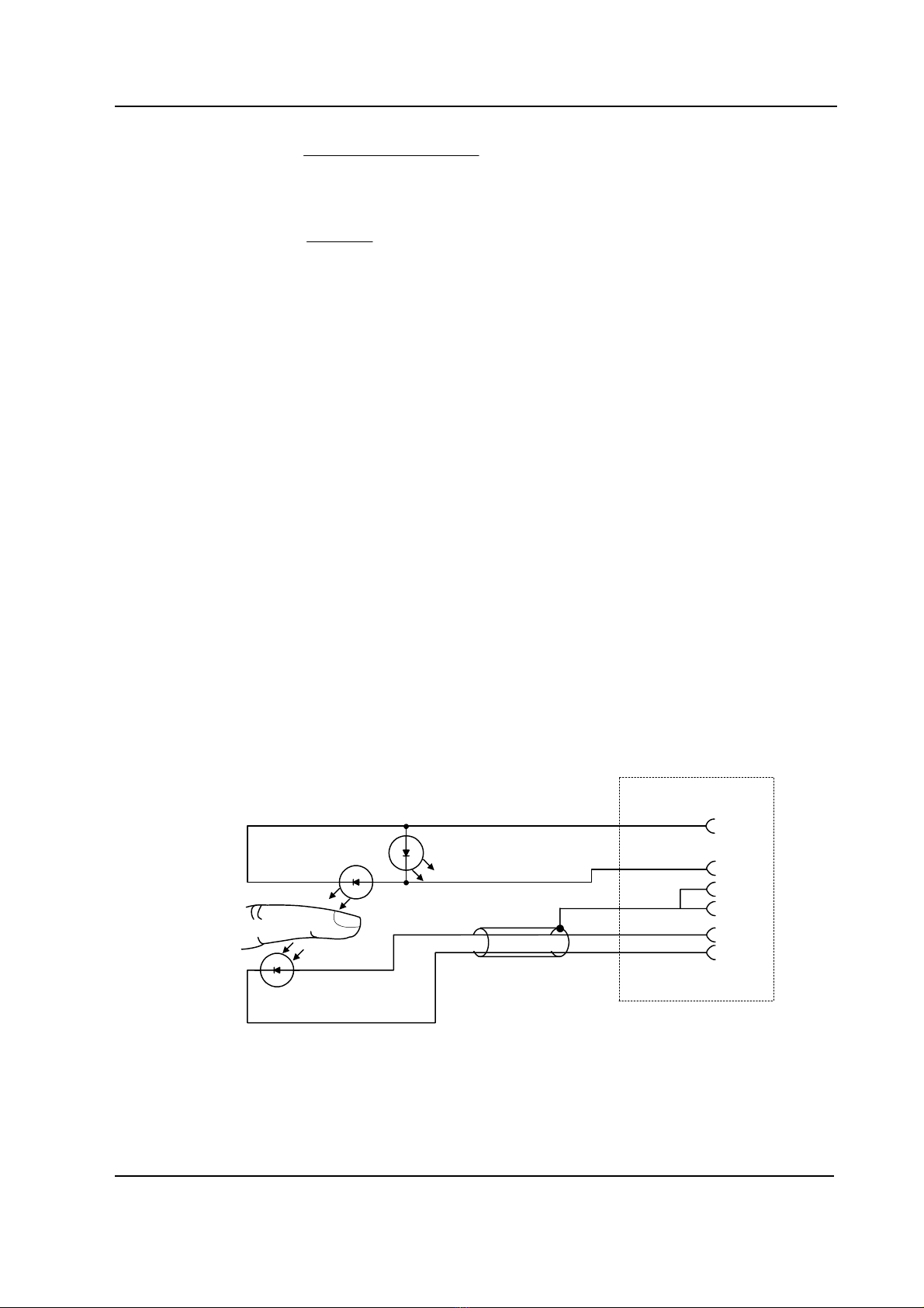
2.1.3 Pulse oximetry
A pulse oximeter measures the light absorption of blood at two wavelengths, one in the near
infrared (about 900 nm) and the other in the red region (about 660 nm) of the light spectrum. These
wavelengths are emitted by LEDs in the SpO2probe, the light is transmitted through peripheral
tissue and is finally detected by a PIN-diode opposite the LEDs in the probe. The pulse oximeter
derives the oxygen saturation (SpO2)using an empirically determined relationship between the
relative absorption at the two wavelengths and the arterial oxygen saturation SaO2.
In order to measure the arterial saturation accurately, pulse oximeters use the component of light
absorption giving variations synchronous with heart beat as primary information on the arterial
saturation.
A general limitation of pulse oximetry is that due to the use of only two wavelengths only two
hemoglobin species can be discriminated by the measurement.
The modern pulse oximeters are empirically calibrated either against fractional saturation SaO2frac;
S/5 M-PRESTN Modules
9
Document No. 8005571-1
binDyshemogloHbHbO
HbO
fracSaO
2
2
2++
=Formula 1
or against functional saturation SaO2func;
HbHbO
HbO
funcSaO
2
2
2+
=Formula 2
Functional saturation is more insensitive to changes of carboxyhemoglobin and methemoglobin
concentrations in blood.
The oxygen saturation percentage SpO2measured by the Datex-Ohmeda module is calibrated
against functional saturation SaO2func. The advantage of this method is that the accuracy of SpO2
measurement relative to SaO2func can be maintained even at rather high concentrations of
carboxyhemoglobin in blood. Independent of the calibration method, pulse oximeters are not able
to correctly measure oxygen content of the arterial blood at elevated carboxyhemoglobin or
methemoglobin levels.
Plethysmographic pulse wave
The plethysmographic waveform is derived from the IR signal and reflects the blood pulsation at the
measuring site. Thus the amplitude of the waveform represents the perfusion.
Pulse rate
The pulse rate calculation is done by peak detection of the plethysmographic pulse wave. The
signals are filtered to reduce noise and checked to separate artifacts.
Probe
The standard probe is a finger clamp probe which contains the light source LEDs in one half and the
photodiode detector in the other half. Different kinds of probes are available from Datex-Ohmeda.
PRSTN_absorption_of_infrared.vsd
Emitter
Detector
SpO2 sensor connector
SpO2 sensor cable
IRED
RED
7
6
4
5
8
9
GND
IS
ILED
GND
DET_C
DEF_A
Figure 2 Absorption of infrared light in the finger probe, parts layout and schematic
diagram

Datex-Ohmeda S/5 monitors
10
Document No. 8005571-1
2.1.4 Temperature
The temperature is measured by a probe whose resistance varies when the temperature changes,
called NTC (Negative Temperature Coefficient) resistor.
The resistance can be measured by two complementary methods:
• Applying a constant voltage across the resistor and measuring the current that flows
through it
• Applying a constant current through the resistor and measuring the voltage that is
generated across it.
In Datex-Ohmeda modules the two methods are combined in the form of a voltage divider. The NTC-
resistor is connected in series with a normal resistor and a constant voltage is applied across them.
The temperature dependent voltage can be detected at the junction of the resistors, thus producing
the temperature signal from the patient. The signal is amplified by analog amplifiers and further
processed by digital electronics.
2.1.5 Invasive blood pressure
To measure invasive blood pressure, a catheter is inserted into an artery or vein. The invasive
pressure setup, consisting of connecting tubing, pressure transducer, an intravenous bag of normal
saline all connected together by stopcocks, is attached to the catheter. The transducer is placed at
the same level with the heart, and is electrically zeroed.
The transducer is a piezo-resistive device that converts the pressure signal to a voltage. The monitor
interprets the voltage signal so that pressure data and pressure waveforms can be displayed.
2.1.6 Respiration
Impedance respiration is measured across the thorax between ECG electrodes. The respiration
signal is made by supplying current between the electrodes and by measuring the differential
current from the electrodes. The signal measured is the impedance change caused by breathing.
From these impedance changes, respiration rate is calculated, and the respiration waveform is
displayed on the screen.
S/5 M-PRESTN Modules
11
Document No. 8005571-1
2.2 Main components
2.2.1 M-PRESTN/-RESTN/-PRETN modules
NIBP
ECG
SpO
T1
T2
P1
P2
2
Auto
On/Off
Start
Cancel Zero
P1
Zero
P2
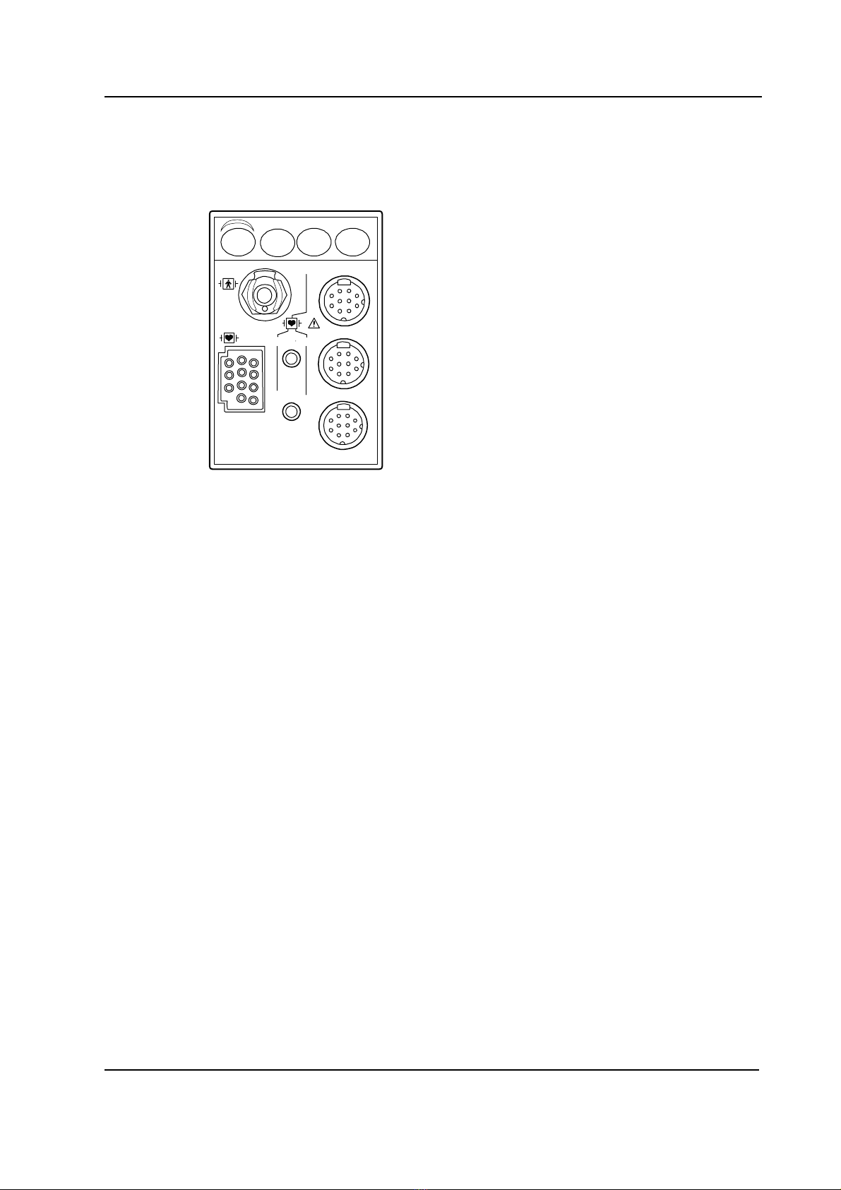
Figure 3 Front panel of M-PRESTN
The M-PRESTN, M-RESTN, and M-PRETN modules contain three main PC boards, the STP board,
the ECG board, and the NIBP board. They work independently. Each of these has their own
processor and software in the processor flash memory.
There are two small boards, the SP input and the ECG input board attached to the front panel of the
module. The front panel has seven connectors and four keys. The connectors are two for
temperature measurement, two for invasive blood pressure measurement, one for ECG, one for
NIBP, and one for SpO2measurement. The keys are for NIBP Auto On/Off, NIBP Start/Cancel, P1
zero, and P2 zero.
Datex-Ohmeda S/5 monitors
12
Document No. 8005571-1
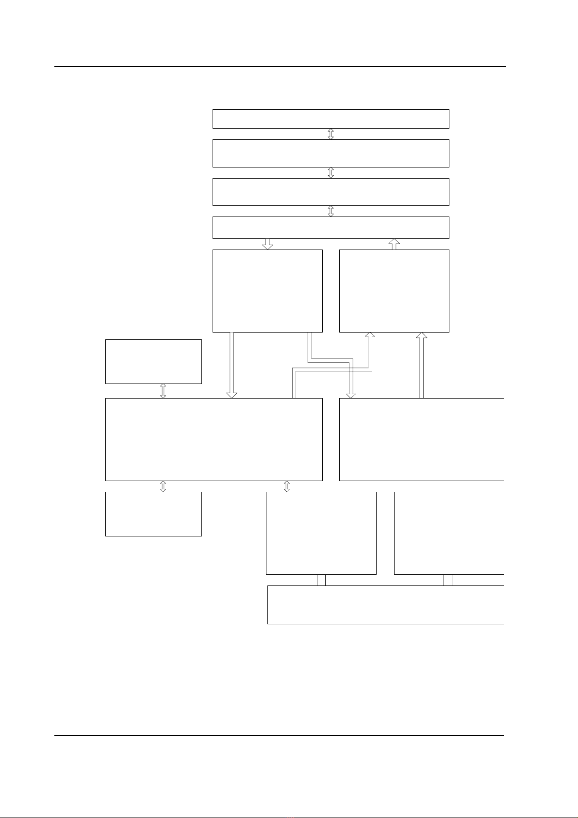
2.2.2 NIBP board
PATIENT AND NIBP CUFF
NIBP TUBING
NIBP CONNECTOR
NIBP PNEUMATICS
PRESSURE SENSORS DRIVERS FOR PUMP &
VALVES
MAIN CPU
RS 485 COMMUNICATION POWER SUPPLY
NV MEMORY
MODULE BUS CONNECTOR
NIBP BLOCK DIAGRAM
SAFETY CPU
NIBP CONTROL KEYS
Figure 4 NIBP board functional block diagram
Signal processing
Two signals from the pressure transducers are amplified and sent to the A/D converter. After the
converter, digitized signals are sent to the microprocessor for data processing.
The NIBP board is controlled with a H8/3052 microprocessor at 16 MHz oscillator frequency.

S/5 M-PRESTN Modules
13
Document No. 8005571-1
Memory
NIBP program memory (processor flash memory) size is 512k ×8. The processor has 4 kBytes RAM
and there is also an external RAM memory the size of which is 128k x 8. Variable values of the NIBP
measurement are stored into the external RAM. The EEPROM size is 512 x 8 and it is used to store
the calibration values for the pressure transducers, the pulse valve constants gained during
measurements, the PC board identification, and module serial number.
Software control
Software controls valves and pump. In addition to the individual on/off signals for each component
there is a common power switch for the valves and the pump that can be used at pump/valve
failures.
In addition to external RS485 reset line the microprocessor system is equipped with its own power-
up reset. See the section in the ECG board’s description: “RS485 communication”
Safety circuit
The NIBP board is equipped with an independent safety circuit to disconnect supply voltages from
the pump and the valves if the cuff has been pressurized longer than the preset maximum
measurement time, or if the pressure of the cuff is inflated over the specified pressure limit. The
maximum measurement time values and pressure limits for different measurement modes have
been specified in the technical specification section of this manual.
Pneumatics
Pneumatics of PRESTN module has the following parts:
• Intake air filter; for preventing dust and other parts to enter the air pump and the
valves.
• Air pump: for pumping the measuring pressure of the cuff.
• (Pulse) Valve; for producing a linear pressure fall (bleeding) in order to measure the
blood pressure of the patient.
Note that there has been used also two other names Valve and Set valve to
designate pulse valve in service menu.
• Safety valve; The safety valve has been intended to be used for deflating the cuff in
single fault case, i.e. to prevent too long measurement time or too high inflation
pressure of the cuff.
Note that there has been used also Exh2 valve to designate the Safety valve in
service menu.
• Main pressure sensor; for measuring the pressure of the blood pressure cuff and
the pressure fluctuations caused by arterial wall movement.
• Safety pressure sensor for detection of cuff hose type, cuff loose, cuff occlusion
situations etc.and recognising the pressure sensor fault.
• Cuff connector; for connecting the cuff.

Datex-Ohmeda S/5 monitors
14
Document No. 8005571-1
Safety pressure sensor
Main pressure sensor Dump valve
Proportional valve
Air pump
Intake air filter
Cuff connector
NIBP_pneum_diagr.vsd
Figure 5 NIBP pneumatics diagram
Power supply section of the NIBP board
All connections are established via 25-pin connector (D-type, female). The module needs +15 V
(dirty) power supply to operate. The supply voltage (+15V) is generated in the power supply section
of the S/5 monitor. The other voltages needed for the operation of the NIBP measurement are
made on the NIBP board.
This manual suits for next models
2
Table of contents
Other Datex-Ohmeda Control Unit manuals


Popular Control Unit manuals by other brands

Warner Electric
Warner Electric TCS-200 Installation & operating instructions

Ricoh
Ricoh Be-C1 Technical bulletin

Honeywell
Honeywell Braukmann D05 installation instructions

Bailey
Bailey Infi 90 NTAI02 Instruction

Altronix
Altronix NetWay Series installation guide

Genebre
Genebre 2034 Installation, operation and maintenance manual


