Datex-Ohmeda S/5 M-INT Product manual

Datex-Ohmeda
S/5™ Interface Module, M-INT (Rev. 01)
Technical Reference Manual
All specifications are subject to change without notice.
Document No. 8001021-1
June 2001
Datex-Ohmeda Inc.
3030 Ohmeda Drive
53707-7550 MADISON, WIS
USA
Tel. +1-608-221 1551,Fax +1-608-222 9147
www.us.datex-ohmeda.com
Datex-Ohmeda Division,
Instrumentarium Corp.
P.O. Box 900, FIN-00031
DATEX-OHMEDA, FINLAND
Tel. +358 10 394 11 Fax +358 9 146 3310
www.datex-ohmeda.com
Instrumentarium Corp. All rights reserved.


Table of contents
Document No. 8001021-1
i
TABLE OF CONTENTS
Interface Module, M-INT (Rev. 01)
TABLE OF CONTENTS i
TABLE OF FIGURES i
Introduction 1
1 Specifications 2
1.1 Serial I/O Definitions ................................................................................................................................2
1.2 Analog definitions.....................................................................................................................................2
2 Functional Description 3
2.1 Main components.....................................................................................................................................4
2.2 Connectors and signals.............................................................................................................................5
2.2.1 Module bus connector......................................................................................................................5
2.2.2 Interface board connectors ...............................................................................................................6
2.2.3 Front panel connectors .....................................................................................................................6
3 Service Procedures 8
3.1 General Service Information ......................................................................................................................8
3.2 Service check ...........................................................................................................................................8
3.2.1 Recommended tools ........................................................................................................................8
3.3 Disassembly and reassembly..................................................................................................................12
4 Troubleshooting 13
4.1 Troubleshooting chart .............................................................................................................................13
5ServiceMENU 14
5.1 Interface menu .......................................................................................................................................15
6 Spare Parts 17
6.1 Spare Parts List.......................................................................................................................................17
6.1.1 Interface Module, M-INT, Rev. 00....................................................................................................17
6.1.2 Interface Module, M-INT, Rev. 01....................................................................................................18
7 Earlier Revisions 19
APPENDIX A 21
Service check form A-1
TABLE OF FIGURES
Figure 1 Interface Module, M-INT........................................................................................................................1
Figure 2 Interface Module, M-INT, block diagram ................................................................................................3
Figure 3 Exploded view of module box and M-INT ..............................................................................................17


Interface Module, M-INT
Document No. 8001021-1
1
INTRODUCTION
The Interface Module, M-INT, provides an interface between the S/5 Critcal Care and Anesthesia
Monitors and other external monitors such as, Datex-Ohmeda Cardiocap and Capnomac Ultima,
Criticon Dinamap 1846 SX, and Abbott Oximetrix 3.
Figure 1 Interface Module, M-INT
NOTE: The Interface Board, B-INT, and Interface Module, M-INT, cannot be used simultaneously in
the same monitor.

Datex-Ohmeda S/5 monitors
Document No. 8001021-1
2
1SPECIFICATIONS
1.1 Serial I/O Definitions
•RS-232 buffered (channels 1-2)
•All standard baud rates are possible from 300 to 115200
•Each interfaced device has fixed baud rate.
1.2 Analog definitions
•There are four analog inputs available on channel 1 and four on channel 2.
•All analog inputs are Op-Amp buffered, with an input impedance of 1 MΩ. Each analog
input is also equipped with a 1 MΩpull-down resistor to -12 V for NC detection.
•Sampling rate: 10 ms/sample/channel
•Input range: -10 V...+10 V
•Resolution: 10 bits →1024 voltage levels in input range
Interface Module, M-INT
Document No. 8001021-1
3
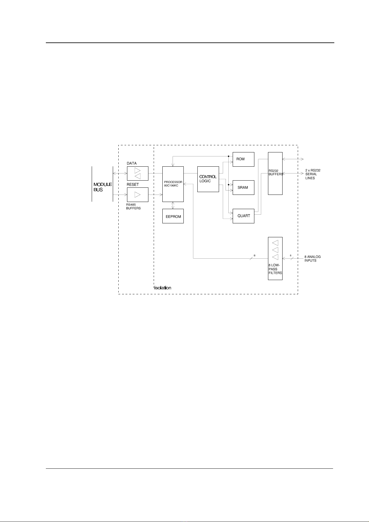
2FUNCTIONAL DESCRIPTION
The Interface Module, M-INT, detects and identifies the external monitors connected to the
module. The identification is made by a serial string, sent by the external monitor.
When an external monitor is connected to the Interface Module, numeric data is always displayed
on the monitor screen. Also, analog real time waveforms are displayed, if the external monitor is
able to send them.
Connections from the Interface Module to external monitors are isolated from S/5 monitor.
Figure 2 Interface Module, M-INT, block diagram

Datex-Ohmeda S/5 monitors
Document No. 8001021-1
4
2.1 Main components
The Interface Module contains an 80C196KC16 microprocessor.
External Connections
The connectors on the Interface Module are:
•One 25-pin D-connector X1 for the module bus.
•Two 9-pin connectors, X2 and X3, for external monitors. These are internally connected to
two 9-pin female D-connectors via ribbon cables.
Each X2 and X3 connector has an RS-232 serial communication channel and four analog inputs.
RS-485 Serial Communication
The Interface Module uses RS-485 signal levels when communicating with the external monitor.
The RS-485 signals are transformed to digital signal levels and fed via an opto-isolator to the
microprocessor. The communication signals for transmitting (TxD) and receiving (RxD) data are sent
to the microprocessor ports. The direction of the communication is controlled by REC/SND signals,
generated by the microprocessor, via the opto-isolator. When the module bus is reset, the
communication is always set to the receiving state.
Reset
The interface board resets when module bus is reset. The RESET signal is converted from an RS-
485 signal level to a digital signal level and then fed to an opto-isolator. The RESET signal is
renamed to POWEROK signal. The POWEROK signal resets the microprocessor and the GAL circuit.
RS-232 Serial Communication
A QUART is used to provide four serial communication channels with external monitors. However,
only two channels are used. The microprocessor controls resetting of the QUART during normal
operation. When the microprocessor is reset the QUART is also reset.
Memories
There are static RAM, ROM, EEPROM memories fitted to the Interface Module. The memory
decoding is done by the GAL circuit. The microprocessor communicates with the EEPROM in serial
mode.
Analog Inputs
Eight analog inputs from the serial/analog connectors are connected to eight low pass filters. The
frequency limit (-3 dB) is set to 35 Hz. The input signal levels are between -10 V and +10 V, and the
output signals are scaled between 0 V and 5 V. The output signals are then fed to the
microprocessor A/D inputs.

Interface Module, M-INT
Document No. 8001021-1
5
2.2 Connectors and signals
2.2.1 Module bus connector
13
1
14
25
Module Bus Connector (X1)
Pin No I/O Signal
1 O RESET_RS485
2 O -15 VDC
3 O +15 VDIRTY
4 O +15 VDC
5 I/O -DATA_RS485
6 I/O DATA_RS485
7 Ground & Shield
8 O -RESET_RS485
9 O CTSB
10 I RTSB
11 O RXDB
12 I TXDB
13 Ground & Shield
14 O +32 VDIRTY
15 O GroundDIRTY
16 O CTSC
17 I RTSC
18 O RXDC
19 I TXDC
20 ON/STANDBY
21 BIT0IN
22 RXDD_RS232
23 TXDD_RS232
24 O +5 VDC
25 O +5 VDC

Datex-Ohmeda S/5 monitors
Document No. 8001021-1
6
2.2.2 Interface board connectors
Power test connector (X11)
Pin No Signal
1 +5 V TEST
2 +5 V ref
3 +12 V
4 GND
5 -12 V
6NC
Analog test connector (X5)
This connector is for factory tests only.
Pin No Signal
1ACH0
2ACH1
3ACH2
4ACH3
5ACH4
6ACH5
7ACH6
8ACH7
9 GND
2.2.3 Front panel connectors
69
15
Serial/Analog connector(X2) CH 1 (floating, off-board)
Pin No Definition
1 A0 analog input
2RXD
3TXD
4 A1 analog input
5 GND
6 A2 analog input
7RTS
8CTS
9 A3 analog input

Interface Module, M-INT
Document No. 8001021-1
7
Serial/Analog Connector (X3) CH 2 (floating)
Pin No Definition
1 A4 analog input
2RXD
3TXD
4 A5 analog input
5 GND
6 A6 analog input
7RTS
8CTS
9 A7 analog input
Datex-Ohmeda S/5 monitors
Document No. 8001021-1
8
3SERVICE PROCEDURES
3.1 General Service Information
Field service of the Interface Module, M-INT, is limited to replacing faulty circuit boards. A faulty
circuit board should be returned to Datex-Ohmeda for repair.
Datex-Ohmeda is always available for service advice. Please provide the unit serial number, full
type designation, and a detailed description of the fault.
CAUTION Only trained personnel with appropriate equipment should perform the tests and
repairs outlined in this section. Unauthorized service may void warranty of the unit.
3.2 Service check
These instructions include complete procedures for a service check. The service check is
recommended to be performed after any service repair. However, the service check procedures can
also be used for determining possible failures.
The procedures should be performed in ascending order.
The instructions include a check form (Appendix A) which should be filled in when performing the
procedures.
The mark ?in the instructions means that the check form should be signed after performing
the procedure.
The procedures are designed for monitors with S/5 monitor software of revision 01. However, most
of the procedures also apply to monitors, which contain some other monitor software
type/revision.
3.2.1 Recommended tools
Tool Order No. Notes
Datex-Ohmeda gas monitor with the SpO2measurement e.g. ULT-S
INT Interface cable 892377
Calibration gas
SpO2probe
Screwdriver
•Detach the module box by removing the two screws from the back of the module. Be careful
with the loose latch and spring locking pin.
1. Check internal parts:
•screws are tightened properly

Interface Module, M-INT
Document No. 8001021-1
9
•cables are connected properly
•all socket mounted IC’s are inserted properly
•the EMC cover is attached properly
•there are no loose objects inside the module
?
2. Check external parts:
•the front cover and the front panel sticker are intact
•the block screws for cables are in place and are tightened properly
•the block screw threads are intact
•all connectors are intact and are attached properly
•the module box, latch and spring locking pin are intact
?
Reattach the module box and check that the latch moves properly.
3. Plug the Interface Module into the monitor Central Unit. Check that it goes in smoothly and
locks up properly.
?
•Connect the Datex-Ohmeda gas monitor with the interface cable (order code 892377) to
Interface Module, M-INT, connector 1. Lock the cable properly.
•Turn both monitors on.
•Make sure the serial output mode of the Datex-Ohmeda gas monitor being used is set to
NUMERIC.
•Configure the S/5 monitor screen so that all required parameters are shown, for example:
Monitor Setup - Screen 1 Setup - Waveform Fields - Field 5 - Pleth
Field 6 - Co2
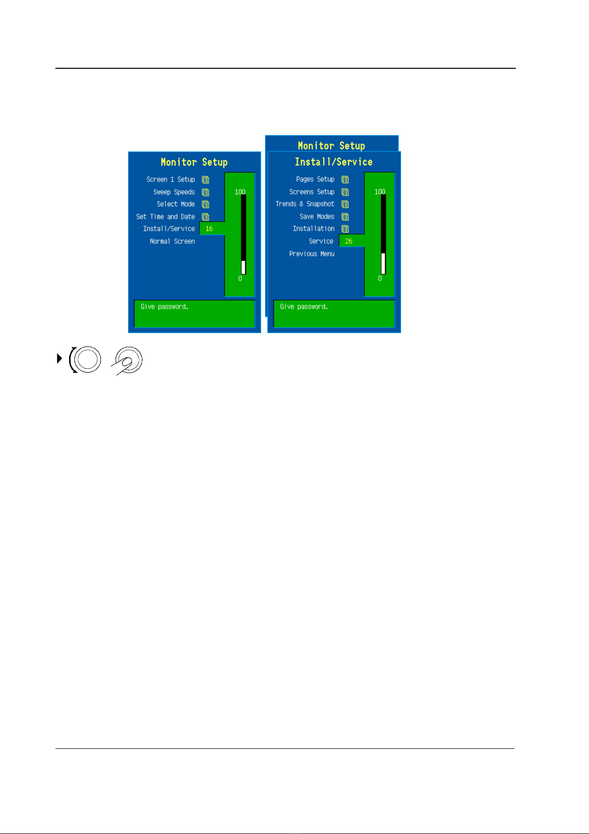
4. Set the interface for the Datex-Ohmeda gas monitor being used:
Monitor Setup - Install/Service (password 16-4-34) - Installation -
Interfacing - Gases/Spiro - XXX
SpO2- XXX
XXX = the gas monitor being used
Check that the menus NIBP and SvO2/C.O. are selectable from the menu.
?

Datex-Ohmeda S/5 monitors
Document No. 8001021-1
10
5. Enter the service menu:
Monitor Setup - Install/Service (password 16-4-34) - Service (password 26-23-8)
Take down the information regarding Interface Module, M-INT, software by selecting SCROLL
VERS and turning the ComWheel.
?
6. Enter the M-INT service menu:
Parameters - More - Interface
Check that the “Timeouts”, “Bad checksums” and “Bad c-s by mod” values are not
increasing faster than by 50 per second. Check that the Interface Module M-INT memories
have passed the internal memory test, i.e. “RAM” and “ROM” state OK.
?
7. Check that the interfaced gas monitor is identified, i.e. the required waveform fields are
shown on the screen and the gas monitor type in shown correctly on the service menu.
Check that the communication state is “online”.
?
8. Select GASES from the M-INT service menu.
Check that “id:” states the correct monitor and interface type, “Active” states YES and
“Timeout” NO.
Check that the numeric values on the service menu are reasonable.
Simulate breathing by feeding calibration gas into the Datex-Ohmeda gas monitor sampling
line and check that the values on the service menu correspond with the values on the gas
monitor screen.
Check that the values in the S/5 monitor gas waveform field are correct and a proper CO2
waveform is shown.
Stop feeding the calibration gas. Check that the message “Apnea” appears in the S/5
monitor waveform field, and in the message field, if the selected interface type is ULT/al.
?
9. Select SpO2from the M-INT service menu.
Check that “id” states the correct monitor and interface type, “Active” states YES and
“Timeout” NO.
Check that “ProbeOff” shows 1 when no SpO2probe is connected to the interfaced gas

Interface Module, M-INT
Document No. 8001021-1
11
monitor. Connect the SpO2probe and check that the “NoProbe” shows 1.
Attach the SpO2probe to your finger and check that the values on the menu correspond with
the values on the gas monitor screen.
Check that the values in the S/5 monitor pleth waveform field are correct and a proper pleth
waveform is shown.
Disconnect the SpO2probe. Check that the message “Probe off “ appears in the S/5
monitor waveform field, and “SpO2probe off” appears in the message field, if the interface
type is ULT/al.
?
10. Turn the gas monitor off. Check that the messages “Interfaced Gas monitor removed” and
“Interfaced SpO2monitor removed” appear on the S/5 monitor screen.
?
11. Turn the S/5 monitor off. Connect the gas monitor with interface cable to Interface Module,
M-INT connector 2.
Turn the monitors on and check that the necessary numerics and waveforms are still
interfaced, together with the alarms, if the interface type is ULT/al.
?
12. Disconnect the Interface Module, M-INT, for a moment, then plug the module back into the
monitor.
Check that interfacing with the gas monitor is restored.
?
13. Perform an electrical safety check and a leakage current test.
?
14. Check that the Interface Module, M-INT, functions normally after performing the electrical
safety check.
?
•Set the interface back for modules:
Monitor Setup - Install/Service (password 16-4-34) - Installation -
Interfacing - Gases/Spiro - Module
SpO2- Module
15. Clean the module with suitable detergent.
?
•Fill in all necessary documents.

Datex-Ohmeda S/5 monitors
Document No. 8001021-1
12
3.3 Disassembly and reassembly
Disassemble the Interface Module, M-INT, in the following way (see figure 3).
1. Remove the two screws from the back of the module.
2. Pull the module box slowly backwards and remove it from the main body.
3. To detach the circuit board, remove four screws and disconnect the two ribbon cables from
the front panel.
To reassemble the module, reverse the order of the disassembly steps.
Interface Module, M-INT
Document No. 8001021-1
13
4TROUBLESHOOTING
Enter the Service Menu (see chapter 5). Select Scroll Vers and scroll down the SW version/Unit id
list. Make sure that the software code and level, control and serial numbers of the Interface
Module, M-INT, are displayed under B-INT/M-INT.
If they are not displayed, the Interface Module, M-INT, is faulty.
4.1 Troubleshooting chart
Trouble Cause Treatment
M-INT not active in the Service Menu.
Software version and ID data are not
available in the Service Data field.
Module is not connected
properly.
M-INT is faulty
Check that the module is firmly
pushed into the module slot.
Replace M-INT Interface board.
Measured values from the interfaced
monitor do not appear on the display
after approximately one minute.
Monitor not selected for
interface.
Poor contact in the interface
cables.
Wrong interface cable.
Select the right monitor from the
Interfacing menu.
Check the cables and
connections. Change the cable to
another connector.
Check cable type and change if
necessary.
Datex-Ohmeda S/5 monitors
Document No. 8001021-1
14
5SERVICE MENU
1. Press the Monitor Setup key.
2. Select Install/Service (password 16-4-34).
3. Select Service (password 26-23-8).
4. Select Parameters - More - Interface.

Interface Module, M-INT
Document No. 8001021-1
15
5.1 Interface menu
Interface
Gases, SpO2, NIBP, Spirometry, SvO2/C.O. indicate the parameters for which service data is
available. The data which can be seen on those pages is raw data from the interfaced monitors,
which will be processed for the normal screen.
Service Data
I-INT: Indicates the status of the interface via the UPI4(NET) Board.
B-INT: Indicates the status of the interface via the 4 interface channels of
B-INT or two channels of M-INT module.
id: The name of the interfaced monitor, e.g. Ultima.
state: describes the state of the connection, alternatives are:
'init' - the channel is initialized
'wait' - the monitor is waiting for the external monitor
'online' - the connection is ready
'search' - the external monitor is being searched
rt: real time values that are available via the interface.
Timeouts is a cumulative number that indicates how many times the module has not responded to
the monitor's inquiry.
Bad checksums is a cumulative number that indicates how many times communication from the
module to the monitor has failed.
Bad c-s by mod is a cumulative number that indicates how many communication errors the
module has detected.
The monitor starts counting these items at power up and resets to zero at power off. The nonzero
values do not indicate a failure, but the continuous counting (more than 50 per second) indicates
either serial communication failure, or module not in place. Also other modules can cause
communication errors which cause these numbers rise.
RAM indicates the state of the RAM memory.

Datex-Ohmeda S/5 monitors
Document No. 8001021-1
16
ROM indicates whether the checksum in the ROM is in accordance with the software calculated
value.
The state is either OK, Fail or ? (module not in place or a communication error).
Table of contents
Other Datex-Ohmeda Control Unit manuals


Popular Control Unit manuals by other brands


Novanta
Novanta JADAK THINGMAGIC EL6E Getting started

Solid Technologies
Solid Technologies HERCULES user manual

EMS
EMS FireCellWDC installation guide

MASCOT
MASCOT DiskFlo Installation, operation & maintenance instructions

MOGAS
MOGAS Watson Series Installation, operation and maintenance manual

Kohler
Kohler K-10668 Homeowner's guide


