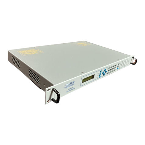
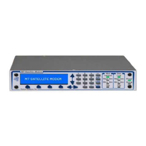
Datum Systems M7XC User manual

M7XC
Compact Satellite Modem
Installation and Operation
Manual

ii
This page is intentionally blank.

M7XC Compact Satellite Modem Table of Contents
v0.02 iii
Table of Contents
Table of Contents ....................................................................................................... iii
Preface………………………………………………………………………………………vi
1 Introduction ..................................................................................... 1-1
Modem Description ..................................................................................... 1-1
Network Types ............................................................................................ 1-2
What’s New – This Modem ......................................................................... 1-5
Modem Assemblies ..................................................................................... 1-6
Capabilities ................................................................................................. 1-7
Forward Error Correction (FEC) Options................................................... 1-11
1:1 Redundancy Function ......................................................................... 1-11
2 Installation .................................................................................... 2-11
Installation Requirements .......................................................................... 2-11
Unpacking ................................................................................................. 2-12
Mounting Considerations .......................................................................... 2-12
Modem Connections ................................................................................. 2-12
3 Operation ....................................................................................... 3-16
Indicators .................................................................................................. 3-16
Operating Procedures ............................................................................... 3-17
Web Browser Operation ............................................................................ 3-17
Remote Command Interface Control ........................................................ 3-58
Modem Configuration ................................................................................ 3-59
Data Interface Technical Details ............................................................... 3-67
Modem Control Channels (MCC + ACM + AUPC) .................................... 3-68
Automatic Uplink Power Control (AUPC) Operation ................................. 3-70
Special Control Mechanisms ..................................................................... 3-70
Trial / Backup Activation Mode .................................................................. 3-72
Built-in 1:1 Redundancy Mode Operation ................................................. 3-73
4 Maintenance ................................................................................. 4-74
Periodic Maintenance ............................................................................... 4-74
Modem Checkout ...................................................................................... 4-74
Updating Modem Firmware ....................................................................... 4-75
Upgrading the Modem Features ............................................................... 4-80
What do the abbreviations in the manual mean? ...................................... 4-83
Appendix A Specification .......................................................................................A-1
Appendix B Remote Protocol ................................................................................B-1
Appendix C Cabling Specifications ....................................................................... C-1
Appendix D Interface Options ............................................................................... D-1
Appendix E Smart Carrier Cancelling ....................................................................E-1
Appendix F Modem SNMP .................................................................................... F-1
Appendix G Modem DVB-S2X Operation ............................................................. G-1
Appendix H Modem TX and RX Carrier Segmentation ......................................... H-1
Appendix J Redundancy Operation ...........................................................................

Table of Contents M7XC Compact Satellite Modem
iv v0.02
Figures
Figure 1-1 - Compact Satellite Modem .................................................................... 1-1
Figure 1-2 - Compact Hub Modems…………………………………………………….1-1
Figure 1-3 - Point-to-Point Network …………………………………………………….1-2
Figure 1-4 - Four (4) Site Point-to-Multipoint Network ……………………………….1-3
Figure 1-5 - Four (4) Site Mesh Network ………………………………………………1-4
Figure 1-6 - Major Assemblies ………………………………………………………….1-6
Figure 1-7 - Functional Block Diagram ………………………………………………...1-6
Figure 1-8 - Spectrum Analyzer Plot …………………………………………………...1-8
Figure 1-9 - Carrier Spacing …………………………………………………………….1-9
Figure 1-10 - Smart Carrier Bandwidth Savings ………………………………….…1-10
Figure 2-1 - Baseband Connections ...................................................................... 2-13
Figure 2-2 - IF Connections ................................................................................... 2-13
Figure 2-3 - Simple Physical Connections …………………………………………...2-17
Figure 2-4 - Simplified Bench Verification Test Diagram ….……………………….2-17
Figure 3-1 - LED Indicators ……………………………………………………………3-18
Figure 3-2 - Login Page ………………………………………………………………..3-19
Figure 3-3 - Web Browser Page Sections ……………………………………………3-20
Figure 3-4 - Web Browser Tab Menu ………………………...………………………3-21
Figure 3-5 - Web Browser Tab Window ……………………………………………...3-21
Figure 3-6 - Unit Status Page …………………………………………………………3-22
Figure 3-7 - Unit Status Page …………………………………………………………3-23
Figure 3-8 - Unit IP Page ………………………………………………………………3-24
Figure 3-9 - Unit HTTP Page ………………………………………………………….3-25
Figure 3-10 - Unit SNMP Page ……………………………………………………….3-26
Figure 3-11 - Unit RS-232 Page ………………………………………………………3-27
Figure 3-12 - Unit Store/Recall ………………………………………………………..3-28
Figure 3-13 - Unit Reference Page …………………………………………………..3-29
Figure 3-14 - Unit Monitor Page ………………………………………………………3-30
Figure 3-15 - Unit Interface Page ……………………………………………………..3-31
Figure 3-16 - Unit Events Page ……………………………………………………….3-32
Figure 3-17 - Unit Alarms Page ……………………………………………………….3-33
Figure 3-18 - Unit Management Page ………………………………………………..3-34
Figure 3-19 - Unit Services Page ……………………………………………………..3-35
Figure 3-20 - TX Status Page …………………………………………………………3-36
Figure 3-21 - TX Modulator Page ……………………………………………………..3-37
Figure 3-22 - TX BUC Page …………………………………………………………...3-38
Figure 3-23 - TX WAN Page …………………………………………………………..3-39
Figure 3-24 - TX MCC Page …………………………………………………………..3-40
Figure 3-25 - TX QoS Custom Page ………………………………………………….3-41
Figure 3-26 - TX QoS WRED Mode Page …………………………………………..3-42
Figure 3-27 - TX QoS Stats Page …………………………………………………….3-43
Figure 3-28 - TX Traffic Stats Page …………………………………………………..3-44
Figure 3-29 - TX Alarms Page ………………………………………………………..3-45
Figure 3-30 - TX Features Page ………………………………………………………3-46
Figure 3-31 - TX Service Page ………………………………………………………...3-47
Figure 3-32 - RX Status Page ………………………………………………………….3-48

M7XC Compact Satellite Modem Specification
v0.02 v
Figure 3-33 - RX Status Page with Constellation ……………………………………3-49
Figure 3-34 - RX Demodulator Page ………………………………………………….3-50
Figure 3-35 - RX Demodulator Page with Spectrum Analyzer …………………….3-51
Figure 3-36 - RX LNB Page ……………………………………………………………3-52
Figure 3-37 - RX WAN Page …………………………………………………………..3-53
Figure 3-38 - RX MCC Page …………………………………………………………...3-54
Figure 3-39 - RX Traffic Stats Page …………………………………………………..3-55
Figure 3-40 - RX Alarms Page ………………………………………………………...3-56
Figure 3-41 - RX Features Page ………………………………………………………3-57
Figure 3-42 - RX Service Page ………………………………………………………..3-58
Figure 3-43 - Serial Address Configuration Web Page ……………………………...3-60
Figure 3-44 - Station ID Configuration Web Page …………………………………..3-61
Figure 3-45 - Store/Recall Configuration Web Page ………………………………..3-63
Figure 3-46 - Reference Connector J1 ……………………………………………….3-63
Figure 3-47- Reference Configuration Web Page …………………………………..3-64
Figure 3-48 - BUC Reference Configuration Web Page ……………………………3-64
Figure 3-49 - LNB Reference Configuration Web Page ……………………………3-65
Figure 3-50 - BUC LO Frequency Configuration Web Page ………………………3-65
Figure 3-51 - LNB LO Frequency Configuration Web Page ………………………3-66
Figure 3-52 - Alarm Processing ………………………………………………………3-67
Figure 3-53 - MCC Configuration Web Page ………………………………………..3-69
Figure 3-54 - MCC Configuration Web Page ………………………………………..3-70
Figure 3-55 - ACM Configuration Web Page ………………………………………..3-71
Figure 3-56 - TAM Web Interface ……………………………………………………..3-73
Figure 4-1 - Unit Feature Page ............................................................................. 4-81
Figure 4-2 - TX Feature Page ............................................................................... 4-81
Figure 4-3 - RX Feature Page ............................................................................... 4-82
Tables
Table 1-1 - Bandwidth Savings Related to Carrier Alpha ........................................ 1-9
Table 2-1 - Multi-Function Connector Pinout (J4) ................................................. 2-14
Table 4-1 – Factory Default Parameters ............................................................... 4-75
NOTE: All appendices may not be present in manual. Some Appendixes may be
shipped with the option.

Preface M7XC Compact Satellite Modem
vi v0.02
Preface
This manual is intended for use by personnel with reasonable knowledge of satellite
communications and earth station terminology. This manual provides Installation,
Operating, and Maintenance procedures for the M7XC Compact Satellite Modem and
available options.
Standard Designations
The M7XC designation is used throughout this manual where references apply to the
M7XC Compact Satellite Modem. The designation for the M7XC may also be referred
to as ‘modem’ or ‘unit’ interchangeably.
Recommended Standard (RS) designations (i.e., RS-232) have been superseded by
the new designation of the Electronic Industries Association (EIA) designations (i.e.,
EIA-232). The RS and EIA designation may be used interchangeably within the
manual and protocol documentation and have the same electrical and mechanical
meaning.
Electrical Safety and Compliance Notice
The M7XC has been safety tested and shown to comply with standard EN 60950
Safety of Information Technology Equipment (Including Electrical Business
Machines).
Never operate the unit with the cover removed. Never remove a cover with power
applied. As a safety measure the power cord must be disconnected from the unit when
preparing to remove the cover.
Battery
The M7XC optionally contains a Lithium Battery. Danger of explosion exists if the
battery is incorrectly replaced. Replace only with the same or equivalent type
recommended by the manufacturer. Dispose of used batteries in accordance with
local and national regulations.
EMC (Electromagnetic Compatibility) and Safety Compliance
This equipment has been tested in accordance with FCC and ESTI standards.
FCC: Part 15, Subpart B, Class A
ETSI EN 301 489-1 V1.9.2 (2011-09) (Emissions and Immunity)
EN 55022 (2010) (Emissions)
EN 55024 (2010) (Immunity)
EN 60950-1:2006 (2nd Edition) and IEC 60950-1:2005 (Safety)
To maintain compliance with these standards the following the precautions must be
observed.
The unit must be operated with the cover attached with all cover screws in
place.

M7XC Compact Satellite Modem Specification
v0.02 vii
All connections are designed to have integral shielding on the cable and
connector assembly.
Telecommunications Terminal Equipment Directive (TTED)
In accordance with the TTED 91/263/EEC, the M7XC should not be connected directly
to the Public Telecommunications Network.
RoHS Compliance
The M7XC satisfies the requirements specified in the European Union Directive on
the Restriction of Hazardous Substances, Directive 2002/95/EC (EU RoHS).
Environmental
The M7XC is designed to operate in an enclosed environment. Operation while
exposed to precipitation, condensation, relative humidity above 95%, excessive dust,
or temperature outside the operating range of -40o C to +60° C temperature range
may cause damage to the unit and will void the warranty. Maximum storage
temperature is -55° C to +70° C.
Do not operate the modem in an unsafe environment near explosive or flammable
gases or liquids.
If the M7XC is to operate in a mobile environment, the user must take precautions to
provide a stable environment consistent with the equipment specifications.
Grounding
Insure good grounding practices. Where a ground lug is provided, the modem should
be connected to a good earth ground with low impedance cable in installations.
About This Manual
This manual is composed of several separable documents. The main body of the
manual is separated into several “Chapters” and “Sections”. The Chapters within the
main manual are the Modem Description, Installation, Operation, and Maintenance.
The Appendices include the Specifications, Remote Control Protocol and information
on Options, Cabling and information related to placing the Modem in service.
A Section is considered a sub-section of a Chapter. For example, Section 4.1.2 is a
numbered section within Chapter 4. Page numbers include the Chapter (i.e., Page 3-
14) and all Tables and Figures will show the Chapter in the caption (i.e., Table 1-2).
This manual is available in a printed form and as an electronic “Portable Document
Format” or .PDF file. The electronic format is produced as a universal Adobe Acrobat
readable file, and can be requested directly from Datum Systems, Inc., or via
download from the web at www.datumsystems.com. The electronic format on the web
is always the latest revision.

Preface M7XC Compact Satellite Modem
viii v0.02
Revision History
Release
Number
Release Date Comments
Revision 0.0
1
0
4
/
01
/20
21
Initial P
ublic Release
Revision 0.0
2
04
/01/202
3
Update
d
to reflect current capabilities
Pen and Ink Changes Made to this Manual
________________________________________________________________
________________________________________________________________
________________________________________________________________
________________________________________________________________
________________________________________________________________
________________________________________________________________
________________________________________________________________
________________________________________________________________
________________________________________________________________
________________________________________________________________
________________________________________________________________
________________________________________________________________
________________________________________________________________
________________________________________________________________
________________________________________________________________
________________________________________________________________
________________________________________________________________
________________________________________________________________
________________________________________________________________
________________________________________________________________
________________________________________________________________
________________________________________________________________
________________________________________________________________

M7XC Compact Satellite Modem Introduction
v0.02 1-1
1 Introduction
Modem Description
The M7XC, represented in Figure 1-1, is a major extension of our innovative design
concepts that have been proven and refined in over twenty years of production.
The M7XC is capable of independent transmission and reception of carriers
compliant to most satellite communications standards. The M7XC uses the latest
Digital Signal Processing (DSP) technology and other proprietary techniques to
provide unsurpassed performance. The M7XC is a highly modular design made
possible by a higher level of integration.
Figure 1-1 - Compact Satellite Modem
The dimensions of the black enclosed M7XC with fan and heatsink are 5” (L) x 3”
(W) x 1.3” (H) and weighs < 2 lbs.
The dimensions of the silver enclosed M7XC without fan and heatsink are 5” (L) x
3” (W) x 1.0” (H) and weighs < 2 lbs.
The M7XC is end-to-end compatible with all Datum Systems M7 series modems.
The M7XC is designed to be integrated into a compact satellite terminal for use in
a variety of satellite systems. The satellite terminals may be small fly-away
systems, Manpack, Airborne/UAV, or other mobile satellite terminal applications.
The M7XC design can also be integrated with other M7XC units into a master hub
station.
Figure 1-2 - Compact Hub Modems
The highly integrated design allows system designers the flexibility to integrate
units into many different innovative hardware system designs. The M7XC is an

Introduction M7XC Compact Satellite Modem
1-2 v0.02
integral part of a satellite earth station’s equipment operating between the Data
Terminal Equipment and the station RF equipment.
The M7XC is designed for operation in different network types. Operating modes
may be dedicated or shared. In a dedicated system two modems are set for
continuous operation with each other. In shared systems, the modem carriers are
typically controlled by a Network Management System (NMS).
Network Types
The M7XC is extremely flexible regarding the network types that can be
configured. Depending on the network type, different baseband interface options
are available that will maximize the capability for the network. The main network
types are:
Point-to-Point
Point-to-Multipoint
Mesh
Hybrid
In a Point-to-Point (P2P) network, the M7XC provides the industry leading Eb/No
performance and flexible baseband interface options. This performance
improvement and the Ethernet/IP interface in the M7XC provide the network
operator with the latest technology needed to extend cellular backhaul connectivity
and Internet access to remote locations. With Ethernet bridging capabilities
internal to the M7XC, there is a significant reduction in the number of devices that
need to be managed and maintained. A typical P2P network is shown in Figure
1-3.
Figure 1-3 - Point-to-Point Network

M7XC Compact Satellite Modem Introduction
v0.02 1-3
Point-to-Multipoint (P2MP) networks are used to connect a central location to
multiple remote locations. The central Hub location will output a continuous carrier
that is received by all the remote sites. The central Hub location will also receive
the individual carriers from each of the remote sites on individual demodulators.
Within the shared outbound carrier will be all the information destined for each of
the remote sites. At each of the remote sites, the M7XC with an Ethernet/IP
interface will filter only the information that is to be received by that site. There is
considerable statistical bandwidth savings by using a shared outbound carrier in
an IP based network because of the typical traffic patterns consistent with IP
networks. A typical P2MP network is shown in Figure 1-4.
Figure 1-4 - Four (4) Site Point-to-Multipoint Network

Introduction M7XC Compact Satellite Modem
1-4 v0.02
A Mesh network is used when all sites in a network need to be connected to all
other sites within that same network with a single satellite link. This could be done
by installing multiple P2P networks between each network site, but as the number
of network nodes increases, there is a dramatic increase in the number of carriers
and an increase in the number of modems required at each site. At some point,
this becomes unmanageable, and cost prohibitive. The alternative is to use a
Mesh network topology instead of multiple P2P networks. At each site in a Mesh
network there is a single carrier that contains all the information destined for all the
nodes within the network. In an IP based network there is considerable statistical
satellite bandwidth savings by using the shared outbound carrier from each site
because of the typical traffic patterns consistent with IP networks. A typical Mesh
network is shown in Figure 1-5.
Figure 1-5 - Four (4) Site Mesh Network
A hybrid network is a combination of any of the networks shown above.

M7XC Compact Satellite Modem Introduction
v0.02 1-5
What’s New – This Modem
The M7XC is similar in operation to the previous Datum Systems M7 modems
except there is no integrated front panel. The monitor and control will be via the
RS-232 serial interface, SNMP, and Web Browser connections. When compared
to the previous modem releases, there are several changes in this modem. The
list below shows some of the differences between the M7XC and the previous
Datum Systems M7 modem products.
1.3.1 M7XC Highlights
Powered by +10 to +36 VDC input with a max of 30 Watts.
Transmit and Receive L-Band 950 to 2250 MHz.
Up to 350 Mbps (Waveform Dependent).
QPSK, 8PSK/APSK, 16APSK, 32APSK, 64APSK, 128APSK and
256APSK.
Contains separate Modulator and Demodulator cards.
Capable of being a TX/RX Modem, a TX only Modulator, or a RX only
Demodulator.
Independent TX/RX FlexLDPC, DVBS2/DVBS2X, and Vit/RS/TPC.
Multi-Demods up to 16 FlexLDPC or two DVBS2X Independent RX
Channels.
Segmented feature up to Sixteen TX FlexLDPC channels.
GigE IP Control interface provides remote control via a HTTP/S web
browser user interface and SNMP protocol.
Complete monitor and control functions as well as firmware/software
updates from the web browser.
IP Control management interface connection is separate from the IP
Data traffic interface connection.
RS-232 serial remote-control interface binary packet control protocol is
also provided.
Baseband traffic Data is connected via the GigE Layer 2 Switched
Bridged Ethernet Protocol interface.
Available with Sharp Carrier Technology that provides eight (8) filter roll-
off options from 0.40 Alpha to 0.02 Alpha.
Available with second-generation advanced carrier canceller for Point-
to-Point (P2P) and Point-to-Multipoint (P2MP) networks.
Compliant with Mil-STD 165B Standard for TX Spurious and Phase
Noise
AES 128/256 (FIPS-140-2 Compliant), 32k P/N Generated Rolling Keys
High Stability 10/50 MHz Reference (In/Out), supports BUC/LNB
Reference
LNB Power (+13 and +18 VDC Selectable)
-40o C to + 60o C Temp Range
MIL-STD-810G – Vibration

Introduction M7XC Compact Satellite Modem
1-6 v0.02
Modem Assemblies
The M7XC consists of four (4) main functional elements arranged on two (2)
electronic printed circuit board assemblies shown in Figure 1-6.
Main Demodulator HousingHousing
Figure 1-6 - Major Assemblies
The modem assembly consists of the following major assemblies:
A. M7XC digital PSK main board assembly with L-Band carrier generation,
monitor/control microprocessor, GigE control and data interfaces.
B. M7XC digital PSK demodulator board assembly that accepts carriers in the
L-Band frequency range. The Digital Signal Processor Acquisition
subsystem is part of the demodulator board assembly.
C. M7XC ‘clamshell’ metal housing.
A functional block diagram of the M7XC is shown in Figure 1-7.
TX ACM
Packet Buffer
Data Rate
Limiter
TX Idle Packet
Generator
QoS Queues
8 x 16 MB
128 MB
DDR3
Memory
TX MCC
Packet Buffer
QoS Mapper
MAC
Echo
Filter
Internal MAC
Filter
Gb
WAN
Port
Internal MAC
Filter
Gb Ethernet Data
CPU
Gb Ethernet M&C
RS-232
SS
Relay
Form A Alarm
Packet Arbitration
GSE Framer FEC Encoder Modulator
Echo Canceler
Packet Arbitration
RX ACM
Packet Buffer
RX MCC
Packet Buffer
RX Idle Packet
Detector
To CPU
To CPU
Power Supply
+VDC Power
Fan +12 VDC
OCXO
RF & Clock Reference
Reference 10/50 MHz
FEC Decoder
GSE Deframer
Channel - 1
GSE Deframer
Channel...
GSE Deframer
Channel...
GSE Deframer
Channel - N
Channel Mapper
Demodulator
LNB Reference
10/50 MHz
LNB Power
+13/18 VDC
RX IF
BUC Reference
10/50 MHz
TX IF
Figure 1-7 – Functional Block Diagram

M7XC Compact Satellite Modem Introduction
v0.02 1-7
Capabilities
1.5.1 Inter-Facility Interface (IF)
The M7XC transmit and receive L-Band IF frequency range is 950 to 2250MHz.
The M7XC transmit and receive IF also provides for either 10 or 50 MHz Frequency
References for the BUC and/or LNB. The modem is ideal for earth stations that are
designed with block Up and Down conversions.
1.5.2 Reference In/Out (Ref)
The M7XC provides an interface for the external references that are to be supplied to
the modem to frequency lock all signals generated by the modem. This interface may
be configured as an output to provide a reference to other units. The Input or Output
Reference Frequency is configurable to 10 MHz or 50 MHz.
1.5.3 GigE Baseband Interface (IP)
The M7XC connects to the Local Area Network (LAN) via the local GigE Ethernet
interface. The interface supports connections between the LAN and the satellite
modem WAN as part of a point-to-point or a point-to-multipoint network. The GigE
Ethernet interface port is a RJ-45 connector. The Data and IP Control Ethernet
interfaces are separate.
1.5.4 TX and RX Carrier Segmentation
Refer to Appendix H - M7XC Modem TX and RX Carrier Segmentation for details.
1.5.5 Sharp Carrier Technology
The M7XC provides multiple settings for the modulation carrier roll-off that will
permit interoperability with industry standards and increase the number of carriers
that can be placed in a satellite transponder. This Datum Systems capability is
referred to as “Sharp Carrier Technology”.
There are ten (10) filter roll-off options available to the modulator and demodulator
control functions. These selectable filter “Alpha” values are “0.40”, “0.35”, “0.30”,
“0.25”, “0.20”, “0.15”, “0.10”, “0.05” and “0.02”. Figure 1-8 shows a comparison of
two (2) spectrum plots one which is 0.35 Alpha (blue) and the other 0.02 Alpha
(red).

Introduction M7XC Compact Satellite Modem
1-8 v0.02
Figure 1-8 - Spectrum Analyzer Plot of 0.35 verses 0.02 Roll-off factors
A significant benefit of this technology is the reduction in carrier spacing required
on the satellite. With a filter roll-off of 0.4, the carrier spacing would be 1.4 times
the carrier symbol rate. When the carriers are changed to a 0.05 roll-off, this carrier
spacing can be reduced by more than 30% to 1.05 times the carrier symbol rate.
A spectrum analyzer plot demonstrates this capability is shown in Figure 1-9.

M7XC Compact Satellite Modem Introduction
v0.02 1-9
Figure 1-9 - Carrier Alpha = 0.4 vs Carrier Alpha = 0.02 Carrier Spacing
For example, in a typical 36MHz transponder configured with 1Msps carriers with
a 0.4 roll-off there could be twenty-five (25) carriers. If the 1Msps carrier roll-off
was changed to 0.08, there now could be 32 carriers – a 28% increase in
transponder throughput. Table 1-1 shows the relative improvement gained in a
bandwidth limited 36MHz transponder by changing the carrier Alpha settings from
0.4.
Table 1-1 - Bandwidth Savings Related to Carrier Alpha
Carrier Alpha
0.4
0.35
0.3
0.25
0.2
0.15
0.1
0.05
0.02
# of 1Msps
Carriers
25
26
27
28
30
31
32
34
35
% Improvement
from 0.4 Alpha 0
4
8
12
20
24
28
36
40
1.5.6 Smart Carrier Cancelling Overview
Smart Carrier is a patent pending second-generation advanced carrier canceller
which allows two carriers to occupy the same transponder spectrum. Our
advanced carrier canceller not only provides excellent performance but is different
from the other cancellers. Our canceller is a baseband canceller instead of an IF
canceller. The canceller is easy to setup and requires no additional cabling. Smart

Introduction M7XC Compact Satellite Modem
1-10 v0.02
Carrier Cancelling is compatible with all Datum Systems Modulation/FEC types
and is well suited to be used with Sharp Roll-Off factors down to 2%. Our technique
provides a Shannon Capacity improvement of ~ 2 dB, which is a ~50 % increase
in the fundamental channel capacity as shown in Figure 1-10.
Figure 1-10 - Smart Carrier Bandwidth Savings of 50%
Figure 1-11 – P2MP Hub Carrier Canceling Bandwidth Savings
1.5.7 Modem Control Channels (MCC + AUPC + ACM)
The MCC provides AUPC plus ACM plus Remote Modem Control Channels and
Auxiliary Control Bits.
Within the Ethernet baseband interface, the MCC channel is provided without the
need to set-up a separate multiplexer or demultiplexer function.

M7XC Compact Satellite Modem Installation
v0.02 2-11
AUPC operation is under control of the modem while the AUPC facility in the MCC
provides the channel for the information. This channel provides a 500-10 kbps
control channel in each direction to allow the modems at both ends of the link to
interactively maintain the receive Eb/No by controlling the power output at each
transmit site.
Refer to the AUPC operation description in Section 3.8.
Forward Error Correction (FEC) Options
The standard M7XC contains the hardware for FlexLDPC and for DVB-S2X FEC
types with basic functional capability for all standard operating networks.
1.6.1 FlexLDPC FEC
The FlexLDPC FEC performance improvement achieved is the highest and most
flexible of any specialized FEC technology to date, outperforming Viterbi and TPC
across all modes. For example, the FlexLDPC at rate 1/2 can operate at a
sustained Eb/No of +1.5 dB with an error rate less than 10-9.
1.6.2 DVB-S2X
Refer to Appendix G DVB-S2X Operation for more information.
1:1 Redundancy Function
NOTE: Both Primary and Backup modems must be at the same hardware and
firmware versions for redundancy to operate properly.
More information on the set-up and use of the 1:1 redundancy functions and
modes is given in Section 3.11
2 Installation
Installation Requirements
The Datum Systems M7XC Compact Satellite Modem is primarily designed for
installation in an integrated satellite terminal and requires 1.3” (H) x 3” (W) x 5” (D)
of space (excluding cabling). The M7XC is shipped with a mating connector for
connection to DC power. An optional AC to DC external power converter module
designed to accept a 3-wire AC line cord is available on request. Installation and
connection to the AC power line must be made in compliance to local or national
wiring codes and regulations. The M7XC may be placed on a table or other stable
flat surface is required for testing.
CAUTION!!! There are no user-serviceable parts or configuration settings
located inside the M7XC modem chassis.
CAUTION!!! Before initially applying power to the modem, it is a good idea to
disconnect the transmit output from the satellite ground station equipment. This is
especially true if the current modem configuration settings are unknown, where
incorrect settings could disrupt existing communications traffic.

Installation M7XC Compact Satellite Modem
2-12 v0.02
Unpacking
The M7XC was carefully packed to avoid damage and should arrive complete with
the following items for proper installation:
M7XC Modem Unit
DC power mating connector
AC to DC Adapter (Optional)
Installation and Operation Manual plus other information on CD
2.2.1 Removal and Assembly
If using a cutting knife or blade to open the carton, exercise caution to ensure that
the blade does not extend into the carton, but only cuts the tape holding the carton
closed. Carefully unpack the unit and ensure that all the above items are in the
carton. If the Prime AC power available at the installation site requires a different
power cord/AC connector, arrangements to receive the proper power cord will be
necessary prior to proceeding with the installation.
The M7XC is shipped fully assembled and does not require removal of the covers
for any purpose during the installation. All hardware configuration is under software
control. The type of Feature Sets, FEC Options and other configurable options are
available via the Web Browser.
Mounting Considerations
When mounting the unit in an integrated terminal, adequate ventilation must be
provided. The ambient temperature in the enclosure must stay between -40o C to
+ 60 C and held constant for best equipment operation. The air available to the
terminal should be clean and relatively dry. Modem units should not be placed
immediately above high heat or EMF generator to ensure the output signal integrity
and proper receive operation.
Do not mount the modem in an unprotected outdoor location where there is direct
contact with rain, snow, wind, or sun. The modem is designed for enclosed
applications that can be indoor or outdoor.
Tools and accessories required for mounting the modem:
Six (6) 6x32 screws
Screwdriver
The following interface connections must be available at the mounting location:
Prime DC power
50 Transmit IF cable with SMA male connector
50 Receive IF cable with SMA male connector
50 External Reference cable with SMA male connector (Optional)
RJ-45 cables to mate with the modem’s two Ethernet interfaces
Modem Connections
Connections to the modem are located on both ends of the unit. The connector
definitions in the following sections describe the connectors on the modem. Any
Table of contents
Other Datum Systems Modem manuals
Popular Modem manuals by other brands
ActionTec
ActionTec GT701-WG quick start guide
Thuraya
Thuraya ThurayaDSL user manual
Telit Wireless Solutions
Telit Wireless Solutions CE910 Series Hardware user's guide

Best Data
Best Data CMX300 user manual

Vega Absolute
Vega Absolute SI-13 user manual
Paradyne
Paradyne COMSPHERE 3800 Series quick reference
