DAV TECH PCP 005 Product manual

005/ 015 / 050 / 150 / 500 / 1000
DAV TECH SRL
Via Ravizza, 30 - 36075 Montecchio Maggiore (VI) - ITALY
Tel. 0039 0444 574510 - Fax 0039 0444 574324
VOLUMETRIC PUMPS PCP
Installation and
maintenance guide

Index
1 INTRODUCTION pag. 3
1.1 The manual
1.2 Warranty
1.3 Goods receiving
2 TECHNICAL DESCRIPTION pag. 3
2.1 Pumps operation
2.2 Technical specifications
3 GETTING STARTED pag. 4
3.1 Pump
005/ 015 / 050 / 150 / 500 / 1000 composition
3.2 Notes before use
3.3 Connection A (stator) B (rotor)
3.4 Eliminating bubbles before dispensing the fluid
4 TYPICAL SETUP pag. 6
5 PUMP MAINTENANCE pag. 8
6 TROUBLESHOOTING pag. 10
7 SYSTEM PRINCIPLES pag. 11
8 BREAKDOWNS pag. 12
8.1 Breakdown Pump
005
8.2 Breakdown Pump
015
8.3 Breakdown Pump
050
8.4 Breakdown Pump
150
8.5 Breakdown Pump
500
8.6 Breakdown Pump
1000
Installation and maintenance guide

pag.3
VOLUMETRIC PUMPS PCP
1 INTRODUCTION
1.1 The manual
The user guide is the document that accompanies the pumps from the time of its construction and throughout the period of
use, it is therefore an integral part of the pump. It requires reading the manual before taking any action involving the pump. The
manual must be readily available for use by staff and maintenance of the pump. The user and the attendant use are required to
know the contents of this manual.
Reproduction of any part of this manual, in any form, without the express written permission of DAV Tech. The text and
illustrations in this manual are not binding, the DAV Tech reserves the right, at any time and without notice, the right to make any
changes to improve the product or for reasons of character manufacturing or commercial.
1.2 Warranty
The warranty is valid for a period of 12 months from the date of commissioning and no later than 15 months from the date
delivery. The interventions carried out during the warranty period does not extend in any way the validity period of the guarantee.
The seller is not liable for defects caused by normal wear of parts which by their nature are subject to wear.
1.3 Goods receiving
The original configuration of the pump must never be changed. Upon receipt of the goods, check that:
• The packaging is intact
• The exact correspondence of the material ordered.
2 TECHNICAL DESCRIPTION
2.1 Pumps operation
The PCP volumetric pumps is the state of art in the micro-dispensing world. The pumps are drived by a gearmotor with encoder
and allow volumetric dispensing in strips, drops, or fill a determinated volume with the highest accuracy, without be affected
from inlet fluid pressure, viscosity and temperature of the media etc. The motor, drived in one direction dispense the fluid, and if
drived in the other direction suck back the fluid, preventing dripping and levelling the pressure on the nozzle.
2.2 Technical specification upon request
Item
PCP-005 PCP-015 PCP-050 PCP-150 PCP-500 PCP-1000 PCP-2000
Dimensions 27xL230xØ27mm 27xL230xØ27mm 27xL230xØ27mm 29xL280xØ29mm 29xL280xØ29mm 29xL312xØ29mm 60xL580xØ60mm
Weight
360 g 360 g 374 g 532 g 530 g 700 g 3,5 kg
Input pressure
0~6 bar 0~6 bar 0~6 bar 0~6 bar 0~6 bar 0~6 bar 0~6 bar
Max. Dispensing pressure
20 bar 20 bar 20 bar 20 bar 15 bar 20 bar 20 bar
Viscosity
0~1.000.000 mPa.s0~1.000.000 mPa.s0~1.000.000 mPa.s0~1.000.000 mPa.s0~1.000.000 mPa.s0~1.000.000 mPa.s0~1.000.000 mPa.s
Dispensing Volume/Rev.
≈0.0049 ml ≈0.017 ml ≈0.049 ml ≈0.17 ml ≈0.45 ml ≈1.1 ml ≈2.0 ml
Motor Speed (rpm)
1~120 rpm 1~120 rpm 1~120 rpm 1~120 rpm 1~120 rpm 1~120 rpm 1~150 rpm
Dispensing Flow Rate (Max.)1
≈0.6 ml/min ≈1.8 ml/min ≈6.0 ml/min ≈18 ml/min ≈60 ml/min ≈120 ml/min ≈280 ml/min
Accuracy of dispensing
±1% ±1% ±1% ±1% ±1% ±1% ±1%
Stator Material
FFKM FFKM FFKM FFKM FFKM FFKM FFKM
Material Inlet Port
2G 1/4” 2G 1/4” 2G 1/4” 2G 1/4” 2G 1/4” 2G 1/4” 2G 3/8” 2
Material Outlet Port
3Luer Lock 3Luer Lock 3Luer Lock 3Luer Lock 3Luer Lock 3Luer Lock 3G 3/8”
Wetted Parts Material
4AISI 304 / AL /
UHMW - PE / FKM 4
AISI 304 / AL /
UHMW - PE / FKM 4
AISI 304 / AL /
UHMW - PE / FKM 4
AISI 304 / AL /
UHMW - PE / FKM 4
AISI 304 / AL /
UHMW - PE / FKM 4
AISI 304 / AL /
UHMW - PE / FKM 4
AISI 304 / AL /
UHMW - PE / FKM 4
Operating Condition
10~40°C 10~40°C 10~40°C 10~40°C 10~40°C 10~40°C 10~40°C
1. Depending on the dispensed fluid - 2.Different inlet, as syringe or catridge fittings available upon request - 3. Different outlet possible upon request - 4. Different
materials possible upon request.

3 GETTING STARTED
> Use the accessories specified by DAV Tech. For the choice of nozzles, evaluate according to the
quantity to be dispensed and the desired application result.
> Keep the pump, its components and accessories clean and protect them from dust or
contamination.
> Replace consumable materials such as syringes and nozzles at every use and clean
contaminated parts such as rotor and stator.
> The digital transducer of the air pressure regulator gives stable results after about 20 minutes
from the start.
1 : Stator
2 : Rotor assembly
3 : Chamber
4 : Motor assembly
5 : Box
6 : Installation tool
7 : Screws, Compass
3.1 Pump 005/ 015 / 050 / 150 / 500 / 1000 composition
3.2 Notes before use
Installation and maintenance guide

pag.5
3.4 Eliminating bubbles before dispensing the fluid
When the pump and the controller’s settings are finished, before applying
pressure to the fluid, rotate the D part (Vent Knob) as the arrow direction
one to two rounds to discharge the air bubbles and some fluid. (about 5~10
seconds). When the fluid flows out freely from the vent valve, close it and
carefully clean the area.
Rotor and stator connection
Do not activate the pump without applying the material to the stator. If so, even for a short
duration of time, there might be a damage on the stator.
When eliminating air bubbles, set the motor speed at “low”
(5~10RPM) to discharge.
Eliminating
air bubbles
3.3 Connection A (stator) and B (rotor)
If the pump has been delivered disassembled, follow the instructions below for assembly.
Use C (fixed tool) to hold the rotor in place and apply the fluid that will be dispensed into A (stator) and
B (rotor). Alternatively, in case there are no contamination problems, it is possible to use vaselline oil
and common grease.
Engage A (stator) on B (rotor) and then turn them clockwise (using tool C) until the tabs shown in the
drawing do not match the seats indicated in the chamber.
VOLUMETRIC PUMPS PCP

4 TYPICAL SETUP
For the proper use of the pump, use the following setting methods to setup.
4.1 Syringe or Cartridge and Controller use
4.2 Tank and Controller use
4.3 Follower plate pump and Controller use
Air hose
Air hose
Pump motor cable
PCP pump
fluid supply hose
fluid supply hose
Controller
Controller
Controller
Cartridges-holder
Syringe
Pressure regulator
Pressure regulator max 5 bar
Pump motor cable
Pump motor cable
PCP pump
PCP pump
fluid supply hose
Air hose
Installation and maintenance guide
Tank

pag.7
4.4 Siringe or Cartridge and Driver use
4.5 Tank and Controller use
4.6 Follower plate pump and Driver use
Air hose
Air hose
Pump motor cable
PCP pump
fluid supply hose
fluid supply hose
Driver
Modbus o Profinet
Cartridges-holder
Syringe
Pressure regulator
Pressure regulator max 5 bar
Pump motor cable
Pump motor cable
PCP pump
PCP pump
fluid supply hose
Air hose
Driver
Modbus o Profinet
Driver
Modbus o Profinet
VOLUMETRIC PUMPS PCP
Tank

5 PUMP MAINTENANCE
Installation and maintenance guide
Follow the instructions below to perform maintenance of the pumps.
A. Prepare the pump and the necessary tools.
B. Turn the screws nr. 1 and unplug it to separate the elements 2 and 3, then unscrew the screws n. 4
(if present) to separate the element nr. 5 and the O-ring (if present).

pag.9
VOLUMETRIC PUMPS PCP
C. Turn the element nr. 6 counter-clockwise to separate the element nr. 7.
Using the fixed tool (supplied) nr. 8, in the motor joint, rotate and separate the stator nr. 9.
E. Unscrew nr. 10 screw (M3x35) to separate the elements nr. 11 and nr. 12.

Installation and maintenance guide
6 TROUBLESHOOTING GUIDE
7 SYSTEM PRINCIPLES
PUMP TROUBLE POSSIBLE CAUSE AND CORRECTION
Fail dispense
1) Check the fluid supply.
2) Check the electrical supply of the controller.
3) Check if there is fluid.
4) Check if the circuit is full of fluid.
5) Check that the nozzle is not clogged.
6) Check the pump motor rotate freely
The quantity
dispensed is not
regular
1) Check to see if there was a change in the controller values setting.
2) Check if the fluid has hardened inside the pump chamber.
3) Check to see if the nozzle is clogged.
4) Check that there are no bubbles in the fluid conduit and inside the pump chamber.
5) Check that the fluid supply pressure is sufficient to keep filled the chamber of the
volumetric pump.
6) Check to see if there is a leak in the fitting of the fluid connection.
The fluid
continues to exit
from the nozzle
at the end of the
dispensation
1) Check if the stator is damaged.
2) Check that there are no air bubbles inside the fluid.
3) Check that there are no air bubbles in the pump.
4) Verify that at rest the motor does not continue to turn.
5) Verify that the pressure of the incoming fluid does not exceed from the one shown in
the datasheet.
The pump motor
does not run
1) Check the connection of the motor cable.
2) Check the setting values of the controller.
3) Check that the fluid has not hardened inside the pump.
When fluid leaks
out from the
body of the pump
1) Check the gaskets between the chamber and the motor.
2) Check the O-ring between the chamber and the gasket block.
The PCP progressive cavity pump is a volumetric pump that can dispense a uniform quantity of fluid
indipendently of its viscosity. The pump is made up of a geared motor, a series of seals, a chamber,
a rotor and a stator. Through an external controller it is possible to control with maximum precision
the rotation of the rotor inside the stator and consequently the quantity of fluid dispensed and the
speed with which it is dispensed. The series of seals allows the fluidic chamber and the eccentric
shaft to be kept separate, avoiding the flow of fluid into the drive parts. The stator makes it possible
to raise the fluid pressure by rotating the rotor inside it.
The PCP pump is a high-performance component but needs careful and timely use and maintenance.

pag.11
VOLUMETRIC PUMPS PCP
END CAP
GEAR
MOTOR
BEARING BLOCK
SEAL BLOCK
ROTOR
UNION CAP
STATOR
CHAMBER
ECCENTRIC SHAFT
O-RING (FKM)
PUMP STRUCTURE
Failure to maintain or use the pump in conditions that do not correspond to those indicated in this
manual may result in total damage to the pump itself.
DAV Tech is pleased to support customers by advising them in the choice of the model that suits
their needs, supplying spare parts or even signing scheduled maintenance contracts.
Installation and maintenance guide
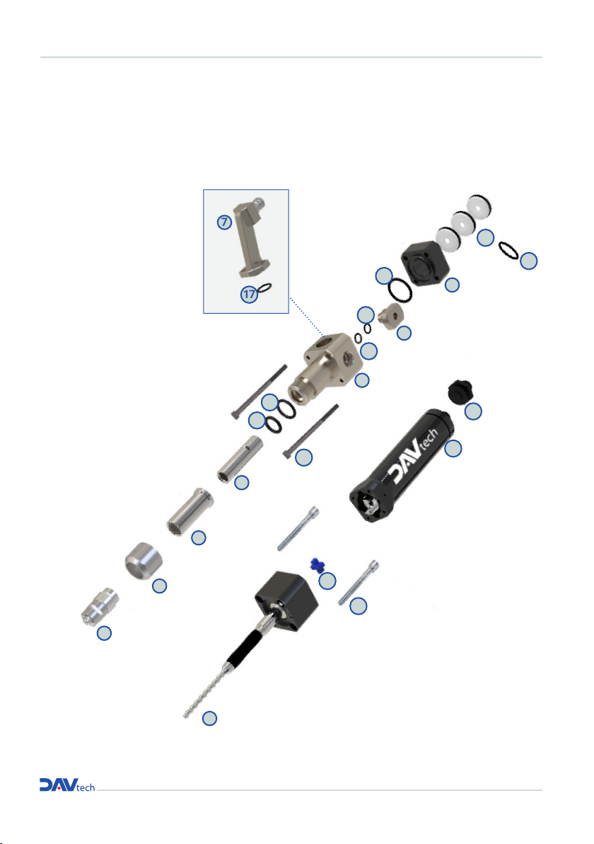
8 BREAKDOWNS
8.1 Breakdown PCP-005
1
2
3
4
5
6
8
9
10
20
16
18
18
19
15
14
21
12
11
13
17
7
Dedicated to
pump model/
body Pump
PCPM extension

pag.13
VOLUMETRIC PUMPS PCP
PCP-005 Components list
Ref. Description Code Additional description
1ROTOR ASSY (including component no. 12)
1.1 PCP-005-ROTOR STAINLESS STEEL ROTOR ASSY PCP-005
1.2 PCP-005-ROTOR-PP POLYPROPYLENE ROTOR ASSY PCP-005
2 SMALL OUTLET ADAPTER PCP
2.1 PCP-LUER-S SMALL LUER LOCK ADAPTOR PCP
2.2 PCP-LUER-S-PEEK SMALL LUER LOCK ADAPTOR PCP PEEK
2.3 PCP-18-S SMALL 1/8" ADAPTOR PCP
2.4 PCP-18-S-PEEK SMALL 1/8" ADAPTOR PCP PEEK
3SMALL COLLAR RING PCP -PCP-NUT-S -
4 STATOR SLEEVE
4.1 PCP-BUSH STATOR SLEEVE PCP-005
4.2 PCP-BUSH-PEEK STATOR SLEEVE PCP-005 PEEK
5 STATOR ASSY
5.1 PCP-005-STATOR FFKM STATOR ASSY PCP-005
5.2 PCP-005-STATOR-EP EPDM STATOR ASSY PCP-005
6 SMALL PCP PUMP BODY
6.1 PCP-BODY-S STANDARD THREADED SMALL BODY PCP (SX)
6.2 PCP-BODY-S-PEEK PEEK THREADED SMALL BODY PCP (SX)
6.3 PCPM-BODY-S INLET MODULE SMALL BODY PCP (SX)
7 SMALL INLET ADAPTER PCP
7.1 PCPM-SYRINGE10CC INLET ADAPTER PCP SYRINGE 10CC
7.2 PCPM-SYRINGE3055CC-S SMALL INLET ADAPTER PCP SYRINGE 30CC
7.3 PCPM-310-S SMALL INLET ADAPTER PCP CARTRIDGE 310CC
7.4 PCPM-SEMCO-S SMALL INLET ADAPTER PCP SEMCO 6 OZ
8 PURGE VALVE PCP
8.1 PCP-PURGE MANUAL PURGE VALVE PCP
8.2 PCP-PURGE-UV MANUAL PURGE VALVE PCP FOR UV
8.3 PCP-PURGE-PEEK MANUAL PURGE VALVE PCP MADE OF PEEK
9 CORPO TENUTE PICCOLO PCP
9.1 PCP-SEALBLOCK-S SMALL ROTARY SEAL BLOCK PCP
9.2 PCP-SEALBLOCK-S-PEEK SMALL ROTARY SEAL BLOCK PCP PEEK
10 SMALL ROTARY SEAL BODY PCP (x 1 pcs) - PCP-ROTARYSEAL -
11 SMALL MOTOR ASSY PCP
(including component no. 13) -PCP-MOTOR-S -
12 SLEEVE MOTOR JOINT FOR SMALL MOTOR PCP - PCP-JOINT-S -
13 SMALL MOTOR CONNECTOR PCP - PCP-CONNECTOR-S -
14 O-RING FKM - PCP-A -
15 O-RING FKM - PCP-B -
16 SCREW SE (x2 pcs) - PCP-1 -
17 O-RING FKM - PCP-C -
18 O-RING (x1 pcs) FKM - PCP-D -
19 O-RING FKM - PCP-E -
20 O-RING (x1 pcs) FKM
20.1 PCP-F -
20.2 PCP-F-FFKM -
21 SCREW SET (x2 pcs) - PCP-2 -
KIT O-RING PCP-005 - GASKETKIT-PCP005 -

Installation and maintenance guide
8.2 Breakdown PCP-015
1
2
3
4
5
6
8
9
10
16
18
18
19
15
14
21
12
11
13
Dedicated to
pump model/
body Pump
PCPM extension
7
20
17

pag.15
VOLUMETRIC PUMPS PCP
PCP-015 Components list
Ref. Description Code Additional description
1 ROTOR ASSY (including component no. 12)
1.1 PCP-015-ROTOR STAINLESS STEEL ROTOR ASSY PCP-015
1.2 PCP-015-ROTOR-PP POLYPROPYLENE ROTOR ASSY PCP-015
1.3 PCP-015-ROTOR-TC CARBIDE ROTOR ASSY PCP-015
1.4 PCP-015-ROTOR-ZC ZIRCONIA ROTOR ASSY PCP-015
2 SMALL OUTLET ADAPTER PCP
2.1 PCP-LUER-S SMALL LUER LOCK ADAPTOR PCP
2.2 PCP-LUER-S-PEEK SMALL LUER LOCK ADAPTOR PCP PEEK
2.3 PCP-18-S SMALL 1/8" ADAPTOR PCP
2.4 PCP-18-S-PEEK SMALL 1/8" ADAPTOR PCP PEEK
3 SMALL COLLAR RING PCP - PCP-NUT-S -
4 STATOR SLEEVE
4.1 PCP-BUSH STATOR SLEEVE PCP-015
4.2 PCP-BUSH-PEEK STATOR SLEEVE PCP-015 PEEK
5 STATOR ASSY
5.1 PCP-015-STATOR FFKM STATOR ASSY PCP-015
5.2 PCP-015-STATOR-EP EPDM STATOR ASSY PCP-015
6 SMALL PCP / PCPM PUMP BODY
6.1 PCP-BODY-S STANDARD THREADED SMALL BODY PCP (SX)
6.2 PCP-BODY-S-PEEK PEEK THREADED SMALL BODY PCP (SX)
6.3 PCPM-BODY-S INLET MODULE SMALL BODY PCP (SX)
7 SMALL INLET ADAPTER PCPM
7.1 PCPM-SYRINGE10CC INLET ADAPTER PCP SYRINGE 10CC
7.2 PCPM-SYRINGE3055CC-S SMALL INLET ADAPTER PCP SYRINGE 30CC
7.3 PCPM-310-S SMALL INLET ADAPTER PCP CARTRIDGE 310CC
7.4 PCPM-SEMCO-S SMALL INLET ADAPTER PCP SEMCO 6 OZ
8 PURGE VALVE PCP
8.1 PCP-PURGE MANUAL PURGE VALVE PCP
8.2 PCP-PURGE-UV MANUAL PURGE VALVE PCP FOR UV
8.3 PCP-PURGE-PEEK MANUAL PURGE VALVE PCP MADE OF PEEK
9 SMALL ROTARY SEAL BODY PCP
9.1 PCP-SEALBLOCK-S SMALL ROTARY SEAL BLOCK PCP
9.2 PCP-SEALBLOCK-S-PEEK SMALL ROTARY SEAL BLOCK PCP PEEK
10 ROTARY SEAL FOR PCP (x 1 pcs) - PCP-ROTARYSEAL -
11 SMALL MOTOR ASSY PCP
(including component no. nr. 13) - PCP-MOTOR-S -
12 SLEEVE MOTOR JOINT FOR SMALL MOTOR PCP - PCP-JOINT-S -
13 SMALL MOTOR CONNECTOR PCP - PCP-CONNECTOR-S -
14 O-RING FKM - PCP-A -
15 O-RING FKM - PCP-B -
16 SCREW SET (x2 pcs) - PCP-1 -
17 O-RING FKM - PCP-C -
18 O-RING (x1 pcs) FKM - PCP-D -
19 O-RING FKM - PCP-E -
20 O-RING (x1 pcs) FKM
20.1 PCP-F -
20.2 PCP-F-FFKM -
21 SCREW SET (x2 pcs) - PCP-2 -
KIT O-RING PCP-015 - GASKETKIT-PCP015 -

Installation and maintenance guide
8.3 Breakdown PCP-050
1
2
3
4
5
6
8
9
10
16
18
18
19
15
14
21
12
11
13
Dedicated to
pump model/
body Pump
PCPM extension
7
17
20

pag.17
VOLUMETRIC PUMPS PCP
PCP-050 Components list
Ref. Description Code Additional description
1 ROTOR ASSY (including component no. 12)
1.1 PCP-050-ROTOR STAINLESS STEEL ROTOR ASSY PCP-050
1.2 PCP-050-ROTOR-PP POLYPROPYLENE ROTOR ASSY PCP-050
1.3 PCP-050-ROTOR-TC CARBIDE ROTOR ASSY PCP-050
1.4 PCP-050-ROTOR-ZC ZIRCONIA ROTOR ASSY PCP-050
2 SMALL OUTLET ADAPTER PCP
2.1 PCP-LUER-S SMALL LUER LOCK ADAPTOR PCP
2.2 PCP-LUER-S-PEEK SMALL LUER LOCK ADAPTOR PCP PEEK
2.3 PCP-18-S SMALL 1/8" ADAPTOR PCP
2.4 PCP-18-S-PEEK SMALL 1/8" ADAPTOR PCP PEEK
3 SMALL COLLAR RING PCP - PCP-NUT-S -
4 STATOR SLEEVE
4.1 PCP-BUSH STATOR SLEEVE PCP-050
4.2 PCP-BUSH-PEEK STATOR SLEEVE PCP-050 PEEK
5 STATOR ASSY
5.1 PCP-050-STATOR FFKM STATOR ASSY PCP-050
5.2 PCP-050-STATOR-EP EPDM STATOR ASSY PCP-050
6 SMALL PCP PUMP BODY
6.1 PCP-BODY-S STANDARD THREADED SMALL BODY PCP (SX)
6.2 PCP-BODY-S-PEEK PEEK THREADED SMALL BODY PCP (SX)
6.3 PCPM-BODY-S INLET MODULE SMALL BODY PCP (SX)
7 SMALL INLET ADAPTER PCP
7.1 PCPM-SYRINGE10CC INLET ADAPTER PCP SYRINGE 10CC
7.2 PCPM-SYRINGE3055CC-S SMALL INLET ADAPTER PCP SYRINGE 30CC
7.3 PCPM-310-S SMALL INLET ADAPTER PCP CARTRIDGE 310CC
7.4 PCPM-SEMCO-S SMALL INLET ADAPTER PCP SEMCO 6 OZ
8 PURGE VALVE PCP
8.1 PCP-PURGE MANUAL PURGE VALVE PCP
8.2 PCP-PURGE-UV MANUAL PURGE VALVE PCP FOR UV
8.3 PCP-PURGE-PEEK MANUAL PURGE VALVE PCP MADE OF PEEK
9 SMALL ROTARY SEAL BODY PCP
9.1 PCP-SEALBLOCK-S SMALL ROTARY SEAL BLOCK PCP
9.2 PCP-SEALBLOCK-S-PEEK SMALL ROTARY SEAL BLOCK PCP PEEK
10 ROTARY SEAL FOR PCP (x 1 pcs) - PCP-ROTARYSEAL -
11 SMALL MOTOR ASSY PCP
(including component no.13) - PCP-MOTOR-S -
12 SLEEVE MOTOR JOINT FOR SMALL MOTOR PCP - PCP-JOINT-S -
13 SMALL MOTOR CONNECTOR PCP - PCP-CONNECTOR-S -
14 O-RING FKM - PCP-A -
15 O-RING FKM - PCP-B -
16 SCREW SET (x2 pcs) - PCP-1 -
17 O-RING FKM - PCP-C -
18 O-RING (x1 pcs) FKM - PCP-D -
19 O-RING FKM - PCP-E -
20 O-RING (x1 pcs) FKM
20.1 PCP-F -
20.2 PCP-F-FFKM -
21 SCREW SET (x2 pcs) - PCP-2 -
KIT O-RING PCP-050 - GASKETKIT-PCP050 -

Installation and maintenance guide
8.4 Breakdown PCP-150
1
2
3
4
5
8
9
1016
18
18
19
15
14
20
12
11
13
7
Dedicated to
pump model/
body Pump
PCPM extension
15
6
17

PCP-150 Components list
pag.19
VOLUMETRIC PUMPS PCP
Ref. Description Code Additional description
1 ROTOR ASSY (including component no. 12)
1.1 PCP-150-ROTOR ROTOR ASSY STAINLESS STEEL PCP-150
1.2 PCP-150-ROTOR-TC ROTOR ASSY CARBIDE PCP-150
1.3 PCP-150-ROTOR-ZC ROTOR ASSY ZIRCONIA PCP-150
2 BIG OUTLET ADAPTER PCP
2.1 PCP-LUER-B BIG LUER LOCK ADAPTOR PCP
2.2 PCP-LUER-B-PEEK BIG LUER LOCK ADAPTOR PCP PEEK
2.3 PCP-18-B BIG 1/8" ADAPTOR PCP
2.4 PCP-18-B-PEEK BIG 1/8" ADAPTOR PCP PEEK
3 BIG COLLAR RING PCP - PCP-NUT-B -
4 STATOR ASSY
4.1 PCP-150-STATOR FFKM STATOR ASSY PCP-150
4.2 PCP-150-STATOR-EP EPDM STATOR ASSY PCP-150
5 BIG PCP/PCPM PUMP BODY
5.1 PCP-BODY-B STANDARD THREADED BIG BODY PCP (SX)
5.2 PCP-BODY-B-PEEK PEEK THREADED BIG BODY PCP (SX)
5.3 PCPM-BODY-B INLET MODULE BIG BODY PCP (SX)
6 BIG INLET ADAPTER PCP
6.1 PCPM-SYRINGE3055CC-B BIG INLET ADAPTER PCP SYRINGE 30CC
6.2 PCPM-310-B BIG INLET ADAPTER PCP CARTRIDGE 310CC
6.3 PCPM-SEMCO-B BIG INLET ADAPTER PCP SEMCO 6 OZ
7 PURGE VALVE PCP
7.1 PCP-PURGE MANUAL PURGE VALVE PCP
7.2 PCP-PURGE-UV MANUAL PURGE VALVE PCP FOR UV
7.3 PCP-PURGE-PEEK MANUAL PURGE VALVE PCP MADE OF PEEK
8 BIG ROTARY SEAL BODY PCP
8.1 PCP-SEALBLOCK-B BIG ROTARY SEAL BLOCK PCP
8.2 PCP-SEALBLOCK-B-PEEK BIG ROTARY SEAL BLOCK PCP PEEK
9 ROTARY SEAL FOR PCP (x 1 pcs) - PCP-ROTARYSEAL -
10 ASSIEME MOTORE GRANDE PCP
(comprensivo del componente nr. 12) - PCP-MOTOR-B -
11 SLEEVE MOTOR JOINT FOR BIG MOTOR PCP - PCP-JOINT-B -
12 BIG MOTOR CONNECTOR PCP - PCP-CONNECTOR-B -
13 O-RING FKM - PCP-G -
14 O-RING FKM - PCP-H -
15 O-RING (x1 pcs) FKM
15.1 PCP-F -
15.2 PCP-F-FFKM -
16 SCREW SET (x2 pcs) - PCP-1 -
17 O-RING FKM - PCP-C -
18 O-RING (x1 pcs) FKM - PCP-D -
19 O-RING FKM - PCP-E -
20 SCREW SET (x2 pcs) - PCP-2 -
KIT O-RING PCP-150 - GASKETKIT-PCP150 -

8.5 Breakdown PCP-500
Installation and maintenance guide
1
2
3
4
5
8
9
10
16
18
18
19
15
14
20
12
11
13
7
15
Dedicated to
pump model/
body Pump
PCPM extension
6
17
This manual suits for next models
5
Table of contents
Other DAV TECH Water Pump manuals

Popular Water Pump manuals by other brands


red lion
red lion 6RLPG-2K manual

Panta Rhei
Panta Rhei Hydro Wizard ECM 75 operating manual

Astral Pool
Astral Pool DMX Variable Pump S Installation, operation and maintenance manual

Aqua Medic
Aqua Medic reefdoser Series Operation manual

red lion
red lion RL-WC50TA owner's manual

Oleo-Mac
Oleo-Mac WP 30 Operators instruction book

i-MO
i-MO ACF5 Original operating manual

FLORABEST
FLORABEST FGPS 1100 B2 translation of original operation manual

SPX FLOW
SPX FLOW 65000 instruction manual

Panta Rhei
Panta Rhei Hydro Wizard ECM 63 operating manual

water source
water source WSTPC50 operating instructions

SPX FLOW
SPX FLOW ULTIMA BILGE 600 GPH instruction manual