DAV DA1000V Product manual
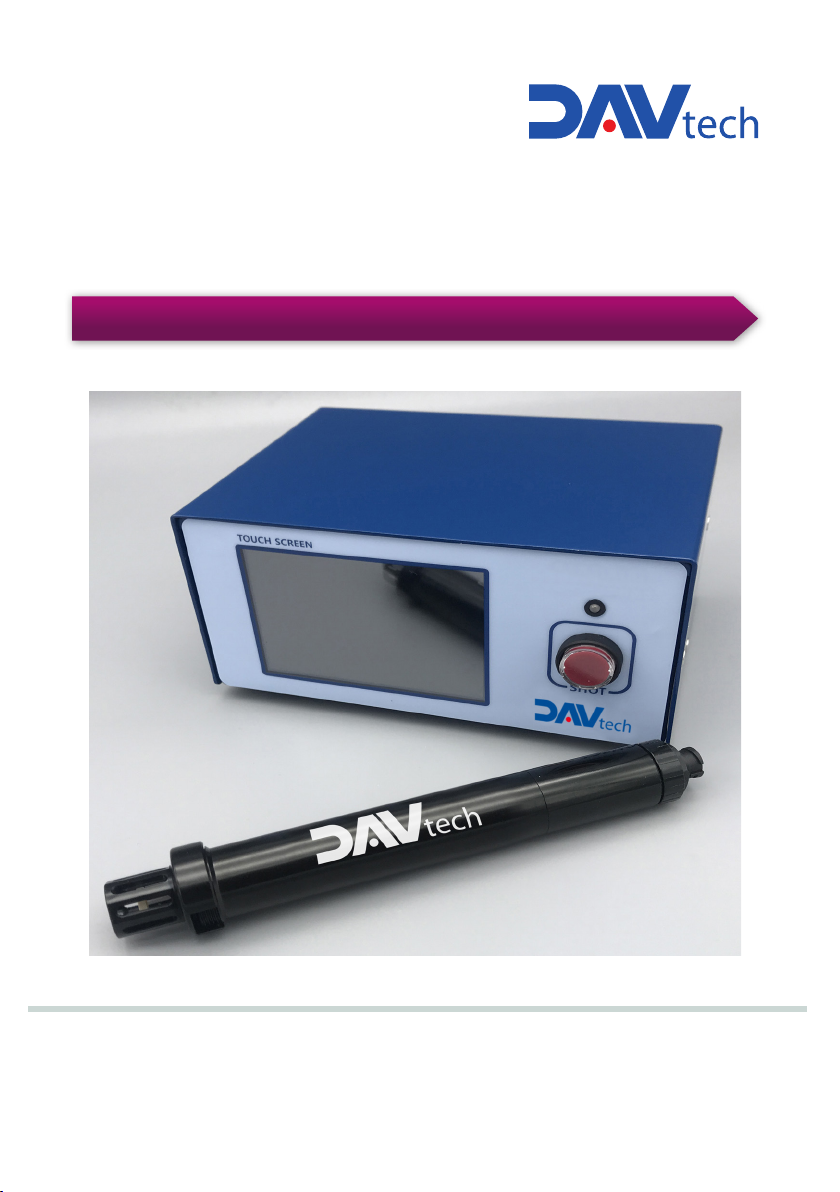
DA1000V VOLUMETRIC MANUAL DISPENSING SYSTEM
DAV TECH SRL
Via Ravizza, 30 - 36075 Montecchio Maggiore (VI) - ITALY
Tel. 0039 0444 574510 - Fax 0039 0444 574324
Installation and
maintenance guide

Index
1 INTRODUCTION pag. 3
1.1 The manual
1.2 Warranty
1.3 Goods receiving
2 TECHNICAL DESCRIPTION pag. 3
3 SAFETY PRECAUTION pag. 4
4 DA 1000V pag. 6
5 DA 1000V CONTROLLER pag. 6
6 BASIC CHECKLIST BEFORE USE pag. 8
7 OPERATION OF THE EQUIPMENT pag.17
8 EXPLANATION OF HMI SCREEN PAGE pag.22
9 PART REPLACEMENT pag. 32
10 INSPECTION AND MEASURES pag. 32
11 TROUBLESHOOTING pag. 33
Installation and maintenance guide

1 INTRODUCTION
1.1 The manual
The user guide is the document that accompanies the Controller from the time of its construction and throughout the period of
use, it is therefore an integral part of the Controller. It requires reading the manual before taking any action involving the Controller.
The manual must be readily available for use by staff and maintenance of the Controller. The user and the attendant use are
required to know the contents of this manual.
Reproduction of any part of this manual, in any form, without the express written permission of DAV Tech. The text and
illustrations in this manual are not binding, the DAV tech reserves the right, at any time and without notice, the right to make any
changes to improve the product or for reasons of character manufacturing or commercial.
1.2 Warranty
The warranty is valid for a period of 12 months from the date of commissioning and no later than 15 months from the date
delivery. The interventions carried out during the warranty period does not extend in any way the validity period of the guarantee.
The seller is not liable for defects caused by normal wear of parts which by their nature are subject to wear.
1.3 Goods receiving
The original configuration of the Controller must never be changed. Upon receipt of the goods, check that:
• The packaging is intact
• The exact correspondence of the material ordered.
2 TECHNICAL DESCRIPTION
2.1 Description
Volumetric system to dispense micro to nano quantity of fluids from syringes with the highest accuracy.
The system dispense the fluid from the desired size syringe pushing a piston moved by an advanced and accurate linear
actuator.
2.2 Technical specification
pag.3
DA1000V VOLUMETRIC MANUAL DISPENSING SYSTEM
Barrel Size
3cc 5cc 10cc 30cc
Weight (g)
118 300
Viscosity (cPs)
1~500.000
Screw Pitch (mm)
0.8 0.8 1.0 1.25
Displacement Step (mm/step)
0.0001 0.0001 0.0003
Section of the barrel (mm2)
70.88 124.69 196.07 401.15
Volume by step (cc)
0.0000073 0.0000128 0.0000250 0.000138
Controller DA 1000V
Dimensions
150x80x110
Weight (g)
932
Power
DC 9V/2A
Mode
Time, steady, sequence, interval
Display
3.5” Touch screen
Interface
RS485 (MODBUS)
Input signal
Contact Input
Output signal
NPN Open Connector

3 SAFETY PRECAUTION
Precautions against electric shock
1. This equipment is kept under high pressure for a while even after the main power supply is cut off. When performing a wiring
work or inspection that touches all terminals of the terminal block, leave it for at least five minutes after shutting off the power
before you start the work.
2. To prevent electric shock and malfunction, please provide class 3 grounding.
(100Ω or less, wire diameter 1.6mm or thicker)
3. Inspection and maintenance of this equipment must be performed by a qualified technician(specialist).
4. Do not inspect equipment with wet hands, when the floor is wet or if there is too much moisture. It may cause electric shock.
5. Be careful not to damage the cable, place heavy objects on it or fold it. In case it is damaged, it may cause electric shock.
Precautions against Fire
1. Do not install this equipment near inflammables, combustible organic solvents or vapors. The heat and electrical operation can
cause fire.
2. If this equipment malfunctions, disconnect the main power supply of the equipment. The high current may cause a fire.
Precautions on Wiring
1. Before conducting wiring work for maintenance etc., be sure to shut off all the external power supplies used by the equipment.
Failure to do so may result in electric shock or damage to the equipment.
2. To supply power or operate the equipment after wiring, be sure to attach the covers inside and outside the equipment. Failure to
do so may result in infury and electric shock.
1. Do not apply main power supply except for that of the voltage specified in this user manual. It may cause malfunction.
2. Make sure that terminal connections and wiring are correct. It may cause malfunction.
3. While the electric current is being applied, do not change the wiring or detach the connector. It may cause injury or equipment
failure.
4. If the power wiring in the driving area is wrong, it may cause injury or damage to the equipment due to malfunction. Be careful.
DANGER
CAUTION
Installation and maintenance guide
THE SAFETY PRECAUTIONS HAVE BEEN CLASSIFIED INTO “DANGER” AND “CAUTION”.
“DANGER” means that dangerous situations can occur and death or serious injury could result, if handled incorrectly.
“CAUTION” means that dangerous situations can occur if handled incorrectly. Also you may get serious injury or
physical damage.
In addition, even if it is indicated as caution, it may lead to serious consequences depending on the situation. Since this is
important for the safety of the user, please make sure you follow the instructions.
!
!

PRECAUTIONS
DANGER
1. When the equipment of our company is used including robots(multi-joint robot, rectangular coordinate robot, desktop robot),
please be sure to install a safety net in the robot operation area, and never approach the operation area during operation.
2. Equipment of our company include driving and rotating parts. Install a safety net on the rotating parts and never approach it
during operation.
CAUTION
Precautions for maintenance and inspection
1. When cleaning or repairing the equipment, be sure to turn off the power and check the internal power supply for complete di-
scharging, and then have it carried out by a qualified maintenance specialist. Maintenance by non-experts can cause breakdown.
2. If there is a breakdown of the equipment, do not disassemble the equipment. Please contact our customer support team.
3. If dust accumulates on the equipment, it may cause malfunction. Clean up the equipment periodically. When cleaning, please
shut off the external power completely and check whether the equipment has been fully discharged. There is a danger of electric
shock.
CAUTION
Precautions for disposal
1. When this equipment is disposed of, treat it as industrial waste.
DANGER
1. Be sure to use the designated power supply. The basic power of the equipment is designated as AC220V 50/60Hz.
2. Be sure to use the designated air pressure. The basic air pressure of the equipment is designated as 5kgf/cm2.
3. Do not operate with wet hands. There is a risk of electric shock.
4. During the operation, do not turn off the power or shut down the air pressure unless the equipment is in danger/caution.
Serious problems may arise with the use of equipment.
Precautions on Installation
1. Do not install, store and use in places exposed to conductive dust, corrosive gas, flammable gas, high temperature, condensa-
tion, wind and rain, etc.
2. Exposure to direct sunlight for a long time will degrade accuracy of the equipment. Do not install, store, or use in areas where
there is direct sunlight.
3. When installing in an enclosed space, install a separate cooling fan to allow the outside air to flow in and out, in order to main-
tain the temperature around the equipment at 40°C or less. Overheating may cause fire or other accidents.
Precautions on Use
1. Never modify this equipment. It may cause electric shock, injury, fire or breakdown.
2. Once you modify this equipment, it cannot be covered by our warranty for defects.
3. Before use, be sure to check that all covers are properly installed and verify if there is no foreign material inside the equipment.
Depending on the circumstances, unexpected operation can occur and may result in injury.
4. If an alarm occurs during use, remove the cause of the alarm, check the safety, and reuse it.
pag.5
DA1000V VOLUMETRIC MANUAL DISPENSING SYSTEM
!
!

4 DA 1000V
4 .1 Features
DAV 1000 V is a compact dispenser that enables ultra-quantitative dispense regardless of changes
in the internal differential head and viscosity of the barrel by adopting a precision linear actuator and
a step motor.
• No need air pressure compensation due to applying Full Electronic Control way.
• Easy to control for various dosing condition by applying All Digital Type & Multi Function Controller.
• Possible to nano dispensing precisely.
DA 1000V 3 : 0.0073μl/step, DA 1000V 5 : 0.0128μl/step, DA 1000V 10 : 0.199μl/step,
DA 1000V 30 : 0.275μl/step.
• Simple design & easy to exchange the barrel by applying advanced design as magnetic technology.
• Compact design for applying to automatic inline machine with high speed dispensing application.
(Max. 0.2ms/step)
• Apply 3cc, 5cc, 10cc, 30cc barrel with exclusive syringe and plunger.
5 DA 1000V CONTROLLER
5 .1 Features
This equipment is applied by using dispenser, and it can be applied to the robot to determine and
adjust the application method.
• One-component dispensing DA 1000V Controller is ideal for spot application and precise and
versatile operation is possible.
• Data recognition with color touch screen is easy to operate.
• With the external interface function, various tasks can be performed continuously.
• Setting and data change are intuitive and easy to operate.
Installation and maintenance guide

5 .2 DA 1000V Controller appearance
pag.7
DA1000V VOLUMETRIC MANUAL DISPENSING SYSTEM
NANO PENNANOPEN Operation Manual Doc. Rev 0
2019/7/2 11/47 Copyright © 2019 by TAEHA CORP. All Rights Reserved
4Features of NPC-10
This equipment is applied by using dispenser, and it can be applied to the robot to determine and
adjust the application method.
One-component dispensing Nano Pen Controller (NPC-10) is ideal for spot application and
precise and versatile operation is possible.
Data recognition with color touch screen is easy to operate.
With the external interface function, various tasks can be performed continuously.
Setting and data change are intuitive and easy to operate.
4.1 Appearance of NPC-10
Item Specification Remarks
Model DA 1000V
Dimension (WxDxH) 150mm x 100mm x 70mm
Power DC 9V/2A
Power Voltage Adapter : 100-240V , 50/60Hz, 1.5A
Display 3.5” TFT LCD Touch Type
Operation Touch Panel, Switch
Operation Mode Time, Steady, Interval, Sequence 4 Mode
I/O Signal Contact input or NPN Open collector
I/O Connector ECH350RM(RP) / ECH350RM(5P) EC350VM(4P)
EC350VM(5P)
Motor connector 21008525-02
Comm. Connector DSUB 9Pin RS-232(Download)
RS-485(make use of)

Picture Name Description
DAV 1000V Controller This is the DAV 1000V controller.
DAV 1000V Cable This is the cable that connects the DAV
1000V to the Controller.
DAV 1000V This is the DAV 1000V
Installation and maintenance guide
6 BASIC CHECKLIST BEFORE USE
6.1 Checking basic Components
This picture above shows the basic components of the DA 1000V Controller, and their descriptions are as
follows.
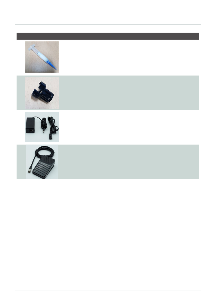
Picture Name Description
Plunger & Barrel
The picture shows the liquid container
barrel that connects to the DA 1000V, and
the plunger(magnet type) that attaches to
the DA 1000V.
Barrel Holder This is the barrel holder used to connect
the DA 1000V and the barrel.
Power connector & Adapter power
connector & Adapter
These are the power connector and
adapter used to supply power
to the DA 1000V Controller
Foot Switch This is the foot switch used to shot the
DA 1000V more conveniently.
pag.9
DA1000V VOLUMETRIC MANUAL DISPENSING SYSTEM
NANO PENNANOPEN Operation Manual Doc. Rev 0
2019/7/2 14/47 Copyright © 2019 by TAEHA CORP. All Rights Reserved
Plunger & Barrel
The picture shows the liquid container barrel that
connects to the nano pen, and the plunger(magnet type)
that attaches to the nano pen.
Barrel Holder This is the barrel holder used to connect the nano pen
and the barrel.
Power connector &
Adapter power
connector &
Adapter
These are the power connector and adapter used to
supply power to the NPC-10.
Foot Switch This is the foot switch used to shot the nano pen more
conveniently.

Installation and maintenance guide
6.2 DA 1000V CONTROLLER Name and Function of Each Component
Figure 2. DA 1000V Controller Front / Rear
Table 1. Name and description of each component of the DA 1000V CONTROLLER
Name and Display Function and Description
NANO PENNANOPEN Operation Manual Doc. Rev 0
2019/7/2 15/47 Copyright © 2019 by TAEHA CORP. All Rights Reserved
5.2 NPC-10 Name and Function of Each Component
Figure 2. NPC-10 Front / Rear
Table 1. Name and description of each component of the NPC-10
Name and Display Function and Description
<Touch Screen>
The setting values and operation elements for the
operation of the Nano Pen can be conveniently
controlled via the Touch Screen.
<STATE L ED>
This is the LED status indicator that shows the
status of NPC-10.
→When status is ~, LED is ON
<SHOT Switch>
The SHOT Switch can be used to initiate
dispensing of the Dispenser.
→Dispensing is based on Touch Screen Setting.
<POWER Switch>
The NPC-10 can be turned on/off using this power
switch button.
<Touch Screen>
The setting values and operation elements for the
operation of the DA 1000V can be conveniently
controlled via the Touch Screen.
This is the LED status indicator that shows the
status of DA 1000V Controller.
> When status is ~, LED is ON
NANO PENNANOPEN Operation Manual Doc. Rev 0
2019/7/2 15/47 Copyright © 2019 by TAEHA CORP. All Rights Reserved
5.2 NPC-10 Name and Function of Each Component
Figure 2. NPC-10 Front / Rear
Table 1. Name and description of each component of the NPC-10
Name and Display Function and Description
<Touch Screen>
The setting values and operation elements for the
operation of the Nano Pen can be conveniently
controlled via the Touch Screen.
<STATE L ED>
This is the LED status indicator that shows the
status of NPC-10.
→When status is ~, LED is ON
<SHOT Switch>
The SHOT Switch can be used to initiate
dispensing of the Dispenser.
→Dispensing is based on Touch Screen Setting.
<POWER Switch>
The NPC-10 can be turned on/off using this power
switch button.
<State Led>
The SHOT Switch can be used to initiate dispensing
of the Dispenser.
> Dispensing is based on Touch Screen Setting.
<SHOT Switch>
NANO PENNANOPEN Operation Manual Doc. Rev 0
2019/7/2 15/47 Copyright © 2019 by TAEHA CORP. All Rights Reserved
5.2 NPC-10 Name and Function of Each Component
Figure 2. NPC-10 Front / Rear
Table 1. Name and description of each component of the NPC-10
Name and Display Function and Description
<Touch Screen>
The setting values and operation elements for the
operation of the Nano Pen can be conveniently
controlled via the Touch Screen.
<STATE L ED>
This is the LED status indicator that shows the
status of NPC-10.
→When status is ~, LED is ON
<SHOT Switch>
The SHOT Switch can be used to initiate
dispensing of the Dispenser.
→Dispensing is based on Touch Screen Setting.
<POWER Switch>
The NPC-10 can be turned on/off using this power
switch button.
The DA 1000V Controller can be turned on/off
using this power switch button.
<POWER Switch>
NANO PENNANOPEN Operation Manual Doc. Rev 0
2019/7/2 15/47 Copyright © 2019 by TAEHA CORP. All Rights Reserved
5.2 NPC-10 Name and Function of Each Component
Figure 2. NPC-10 Front / Rear
Table 1. Name and description of each component of the NPC-10
Name and Display Function and Description
<Touch Screen>
The setting values and operation elements for the
operation of the Nano Pen can be conveniently
controlled via the Touch Screen.
<STATE L ED>
This is the LED status indicator that shows the
status of NPC-10.
→When status is ~, LED is ON
<SHOT Switch>
The SHOT Switch can be used to initiate
dispensing of the Dispenser.
→Dispensing is based on Touch Screen Setting.
<POWER Switch>
The NPC-10 can be turned on/off using this power
switch button.
pag.11
DA1000V VOLUMETRIC MANUAL DISPENSING SYSTEM
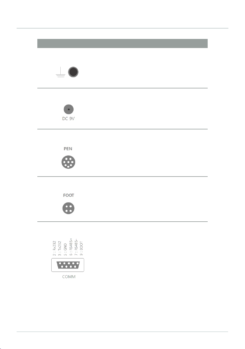
Name and Display Function and Description
This is the grounding connector for the power for the
DA 1000V Controller.
<Frame Ground>
NANO PENNANOPEN Operation Manual Doc. Rev 0
2019/7/2 16/47 Copyright © 2019 by TAEHA CORP. All Rights Reserved
<Frame Ground>
This is the grounding connector for the power for
the NPC-10.
<DC Receptacle>
This can
be connected through the Power
Adaptor.
<Nano Pen Connector>
This is the Connector that connects to the Nano
Pen Cable.
<FOOT Connector>
This is the Connector that is connected in order
to operate the Nano Pen FOOT Switch.
This is a D-SUB 9-
pin Connector, which allows
Firmware Updates as well as 485 communication.
This is the Pin Map used when executing
Controller Firmware Updates.
2: Rx232
3: Tx232
5: GND
9: BOOT
This is the Pin Map used for 485 communication.
6: RS485+
7: RS485−
This is a D-SUB 9-pin Connector, which allows Firmware
Updates as well as 485 communication.
This is the Pin Map used when executing Controller
Firmware Updates.
2: Rx232
3: Tx232
5: GND
9: BOOT
This is the Pin Map used for 485 communication.
6: RS485+
7: RS485
<POWER Switch>
NANO PENNANOPEN Operation Manual Doc. Rev 0
2019/7/2 16/47 Copyright © 2019 by TAEHA CORP. All Rights Reserved
<Frame Ground>
This is the grounding connector for the power for
the NPC-10.
<DC Receptacle>
This can
be connected through the Power
Adaptor.
<Nano Pen Connector>
This is the Connector that connects to the Nano
Pen Cable.
<FOOT Connector>
This is the Connector that is connected in order
to operate the Nano Pen FOOT Switch.
This is a D-SUB 9-
pin Connector, which allows
Firmware Updates as well as 485 communication.
This is the Pin Map used when executing
Controller Firmware Updates.
2: Rx232
3: Tx232
5: GND
9: BOOT
This is the Pin Map used for 485 communication.
6: RS485+
7: RS485−
This is the Connector that is connected in
order to operate the DA 1000V FOOT Switch.
<FOOT Connector>
NANO PENNANOPEN Operation Manual Doc. Rev 0
2019/7/2 16/47 Copyright © 2019 by TAEHA CORP. All Rights Reserved
<Frame Ground>
This is the grounding connector for the power for
the NPC-10.
<DC Receptacle>
This can
be connected through the Power
Adaptor.
<Nano Pen Connector>
This is the Connector that connects to the Nano
Pen Cable.
<FOOT Connector>
This is the Connector that is connected in order
to operate the Nano Pen FOOT Switch.
This is a D-SUB 9-
pin Connector, which allows
Firmware Updates as well as 485 communication.
This is the Pin Map used when executing
Controller Firmware Updates.
2: Rx232
3: Tx232
5: GND
9: BOOT
This is the Pin Map used for 485 communication.
6: RS485+
7: RS485−
This is the Connector that connects to the DA 1000V
Cable.
<DA 1000V Connector>
NANO PENNANOPEN Operation Manual Doc. Rev 0
2019/7/2 16/47 Copyright © 2019 by TAEHA CORP. All Rights Reserved
<Frame Ground>
This is the grounding connector for the power for
the NPC-10.
<DC Receptacle>
This can
be connected through the Power
Adaptor.
<Nano Pen Connector>
This is the Connector that connects to the Nano
Pen Cable.
<FOOT Connector>
This is the Connector that is connected in order
to operate the Nano Pen FOOT Switch.
This is a D-SUB 9-
pin Connector, which allows
Firmware Updates as well as 485 communication.
This is the Pin Map used when executing
Controller Firmware Updates.
2: Rx232
3: Tx232
5: GND
9: BOOT
This is the Pin Map used for 485 communication.
6: RS485+
7: RS485−
This can be connected through the Power
Adaptor.
<DC Receptacle>
NANO PENNANOPEN Operation Manual Doc. Rev 0
2019/7/2 16/47 Copyright © 2019 by TAEHA CORP. All Rights Reserved
<Frame Ground>
This is the grounding connector for the power for
the NPC-10.
<DC Receptacle>
This can
be connected through the Power
Adaptor.
<Nano Pen Connector>
This is the Connector that connects to the Nano
Pen Cable.
<FOOT Connector>
This is the Connector that is connected in order
to operate the Nano Pen FOOT Switch.
This is a D-SUB 9-
pin Connector, which allows
Firmware Updates as well as 485 communication.
This is the Pin Map used when executing
Controller Firmware Updates.
2: Rx232
3: Tx232
5: GND
9: BOOT
This is the Pin Map used for 485 communication.
6: RS485+
7: RS485−

Installation and maintenance guide
OUTPUT Socket
RDY: Indicates the status when control
operation is enabled.
BUSY: Indicates the status when control
operation is in progress.
END: Indicates the end of a control
operation.
ERR: This signal is indicated when an DA
1000V Controller alarm signal occurs.
GND: Set to COMMON to match the DC
potential difference between the host
controller and the DA 1000V Controller.
INPUT Socket
SHOT: Connected when using the dispense
signal from the host controller.
SEL: Used to select the mode from the host
controller.
> Not currently used.
EMG: Used to stop the DA 1000V Controller
from the host controller.
GND: Set to COMMON to match the DC poten-
tial difference between the host controller and
the DA 1000V Controller.
NANO PENNANOPEN Operation Manual Doc. Rev 0
2019/7/2 17/47 Copyright © 2019 by TAEHA CORP. All Rights Reserved
<OUTPUT Socket>
OUTPUT
RDY
BUSY
END
ERR
GND
OUTPUT Socket
RDY: Indicates the status when control operation
is enabled.
BUSY: Indicates the status when control operation
is in progress.
END: Indicates the end of a control operation.
ERR: This signal is indicated when an NPC-10
alarm signal occurs.
GND: Set to COMMON to match the DC potential
difference between the host controller and the NPC-
10.
<INPUT Socket>
INPUT
SHOT
SEL
EMG
GND
INPUT Socket
SHOT:
Connected when using the dispense signal
from the host controller.
SEL:
Used to select the mode from the host
controller.
→ Not currently used.
EMG: Used to stop the NPC-
10 from the host
controller.
GND: Set to COMMON to match the DC potential
difference between the host controller and the NPC-
10.
Name and Display Function and Description
<OUTPUT Socket>
<INPUT Socket>

pag.13
DA1000V VOLUMETRIC MANUAL DISPENSING SYSTEM
6.3 Basic Instructions for Operating the HMI Screen
6.3.1 Switching Pages
NANO PENNANOPEN Operation Manual Doc. Rev 0
2019/7/2 18/47 Copyright © 2019 by TAEHA CORP. All Rights Reserved
5.3 Basic Instructions for Operating the HMI Screen
5.3.1 Switching Pages
Figure 3. How to switch pages - 1
Touching the PAGE ICON, such as the PAGE ICONs shown above, will switch to the corresponding
page.
Figure 4. How to switch pages - 2
You can go to the next PAGE on the GROUP PAGE by touching the arrow icon as indicated above in
Figure 4.
Figure 3. How to switch pages - 1
Touching the PAGE ICON, such as the PAGE ICONs shown above, will switch to the corresponding page.
Figure 4. How to switch pages - 2
You can go to the next PAGE on the GROUP PAGE by touching the arrow icon as indicated above in Figure 4.

Installation and maintenance guide
NANO PENNANOPEN Operation Manual Doc. Rev 0
2019/7/2 19/47 Copyright © 2019 by TAEHA CORP. All Rights Reserved
5.3.2 Changing Settings
Figure 5. Example of changing setting value
When changing the condition value on the SETTING PAGE, please insert a numerical value as shown
in Figure 5.
Figure 6. Example of changing settings
When changing the button setting on the SETTING PAGE, touch the button as shown in Figure 6 to
change the setting value.
Figure 5. Example of changing setting value
When changing the condition value on the SETTING PAGE, please insert a numerical value as shown in Figure 5.
Figure 6. Example of changing settings
When changing the button setting on the SETTING PAGE, touch the button as shown in Figure 6 to change the setting
value.
6.3.2 Changing Settings
NANO PENNANOPEN Operation Manual Doc. Rev 0
2019/7/2 19/47 Copyright © 2019 by TAEHA CORP. All Rights Reserved
5.3.2 Changing Settings
Figure 5. Example of changing setting value
When changing the condition value on the SETTING PAGE, please insert a numerical value as shown
in Figure 5.
Figure 6. Example of changing settings
When changing the button setting on the SETTING PAGE, touch the button as shown in Figure 6 to
change the setting value.

pag.15
1
2
9
DA1000V VOLUMETRIC MANUAL DISPENSING SYSTEM
NANO PENNANOPEN Operation Manual Doc. Rev 0
2019/7/2 20/47 Copyright © 2019 by TAEHA CORP. All Rights Reserved
5.4 Explanation of HMI Screen Structure
Figure 7. NPC-10 HMI Screen Structure
Figure 7 shows the NPC-10 HMI Screen Structure.
Figure 7. DA 1000V Controller HMI Screen Structure
Figure 7 shows the DA 1000V Controller HMI Screen Structure.
6.4 5.4 Explanation of HMI Screen Structure
Installation and maintenance guide
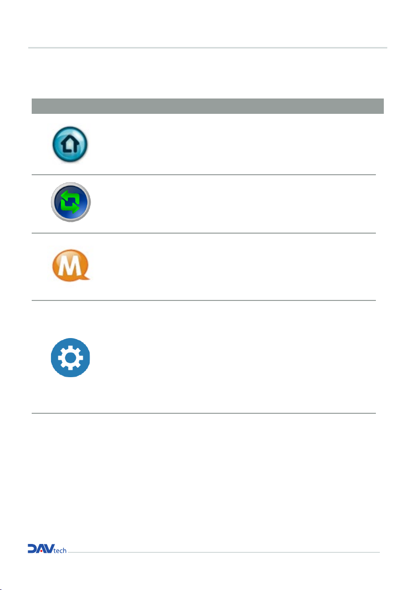
6.4.1 Brief Description of PAGE ICON
ICON PAGE NAME PAGE DESCRIPTION
NANO PENNANOPEN Operation Manual Doc. Rev 0
2019/7/2 21/47 Copyright © 2019 by TAEHA CORP. All Rights Reserved
5.4.1 Brief Description of PAGE ICON
ICON PAGE
NAME PAGE Description
HOME
PAGE
This is the main PAGE that allows the Nano Pen
dispensing mode selection and displays the dispensing
conditions.
BARREL
CHANGE PAGE
This is the PAGE for the Setup and Replacement of the
Nano Pen Barrel.
MENU
PAGE
This is the PAGE to switch to the SETTING, ALARM,
TEST, and INFO PAGEs.
SETTING
PAGE
This is the SETTING PAGE for Nano Pen dispensing.
→MODE (dispensing condition)
→ BARREL (Nano Pen capacity)
→SIGNAL (dispensing type)
→ETC
Settings can be configured.
HOME PAGE
BARREL CHANGE
PAGE
MENU PAGE
SETTING PAGE
This is the main PAGE that allows the DA 1000V
dispensing mode selection and displays the dispen-
sing conditions.
This is the PAGE for the Setup and Replacement of
the DA 1000V Barrel.
This is the PAGE to switch to the SETTING, ALARM,
TEST, and INFO PAGEs.
This is the SETTING PAGE for DA 1000V dispensing.
> MODE (dispensing condition)
> BARREL (DA 1000V capacity)
> SIGNAL (dispensing type)
> ETC
Settings can be configured.
pag.17
DA1000V VOLUMETRIC MANUAL DISPENSING SYSTEM
7.1 Initial Power Input
7 OPERATION OF THE EQUIPMENT
7.2 DA 1000V Capacity Setting
NANO PENNANOPEN Operation Manual Doc. Rev 0
2019/7/2 22/47 Copyright © 2019 by TAEHA CORP. All Rights Reserved
6Operation of the Equipment
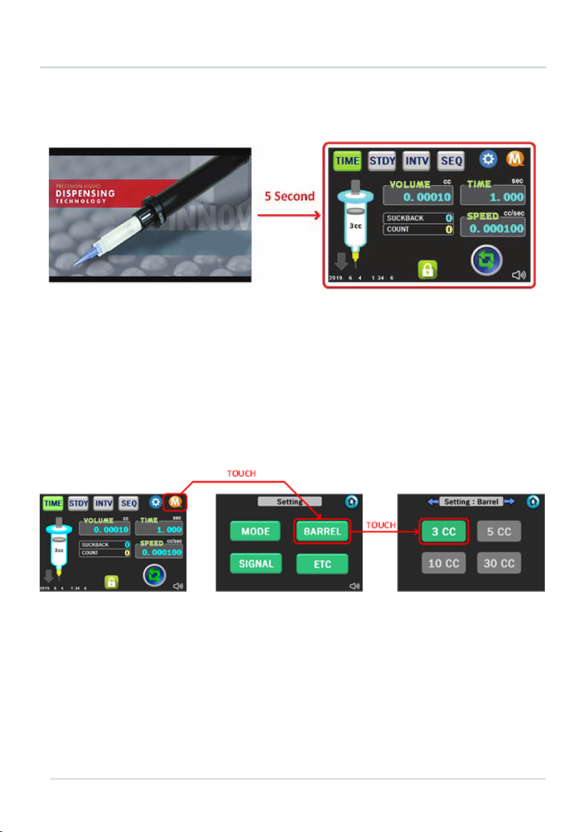
6.1 Initial Power Input
Figure 8. Initial power input screen
When the initial power input is provided by turning on the POWER SWITCH at the back of NPC-10, the
INTRO PAGE will be shown for 5 seconds, after which the screen will switch to the HOME PAGE screen, and
information will be shown in each display window.
6.2 Nano Pen Capacity Setting
Figure 9. Setting the Capacity before using the Nano Pen
The Capacity can be set for the Nano Pen on the NPC-10 before using the Nano Pen.
→ Go to Setting: Barrel PAGE as shown in Figure 9 and set the corresponding capacity value.
Figure 8. Initial power input screen
When the initial power input is provided by turning on the POWER SWITCH at the back of DA 1000V Controller, the
INTRO PAGE will be shown for 5 seconds, after which the screen will switch to the HOME PAGE screen, and informa-
tion will be shown in each display window.
Figure 9. Setting the Capacity before using the Nano Pen
The Capacity can be set for the DA 1000V on the DA 1000V Controller before using the DA 1000V.
> Go to Setting: Barrel PAGE as shown in Figure 9 and set the corresponding capacity value.
Installation and maintenance guide
7.3.1 Accessing the CHANGE BARREL PAGE
7.3.2 Origin position set-up using the auto back
7.3 BARREL Assembly
NANO PENNANOPEN Operation Manual Doc. Rev 0
2019/7/2 23/47 Copyright © 2019 by TAEHA CORP. All Rights Reserved
6.3 BARREL Assembly
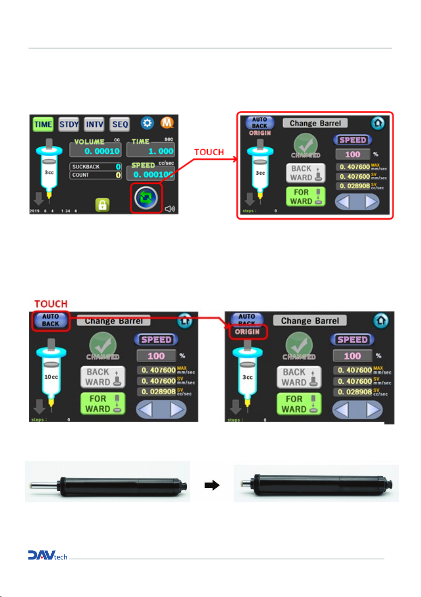
6.3.1 Accessing the CHANGE BARREL PAGE
Figure 10. How to access the Change Barrel PAGE
As shown in Figure 10, touch the Change Barrel icon to access the Change Barrel Page.
6.3.2 Origin position set-up using the auto back function
Figure 11. How to use the AUTO BACK function.
As shown in Figure 12, position the Nano Pen at the ORIGIN Position by using the AUTO BACK function.
Figure 12. Nano Pen in ORIGIN Position after using AUTO BACK
NANO PENNANOPEN Operation Manual Doc. Rev 0
2019/7/2 23/47 Copyright © 2019 by TAEHA CORP. All Rights Reserved
6.3 BARREL Assembly
6.3.1 Accessing the CHANGE BARREL PAGE
Figure 10. How to access the Change Barrel PAGE
As shown in Figure 10, touch the Change Barrel icon to access the Change Barrel Page.
6.3.2 Origin position set-up using the auto back function
Figure 11. How to use the AUTO BACK function.
As shown in Figure 12, position the Nano Pen at the ORIGIN Position by using the AUTO BACK function.
Figure 12. Nano Pen in ORIGIN Position after using AUTO BACK
Figure 10. How to access the Change Barrel PAGE
As shown in Figure 10, touch the Change Barrel icon to access the Change Barrel Page.
Figure 11. How to use the AUTO BACK function.
As shown in Figure 12, position the DA 1000V at the ORIGIN Position by using the AUTO BACK function.
Figure 12. DA 1000V in ORIGIN Position after using AUTO BACK
pag.19
DA1000V VOLUMETRIC MANUAL DISPENSING SYSTEM
7.3.3 Mounting DA 1000V Barrel
7.3.4 Fastening the Plunger
7.3.5 CHANGE SETTING
NANO PENNANOPEN Operation Manual Doc. Rev 0
2019/7/2 25/47 Copyright © 2019 by TAEHA CORP. All Rights Reserved
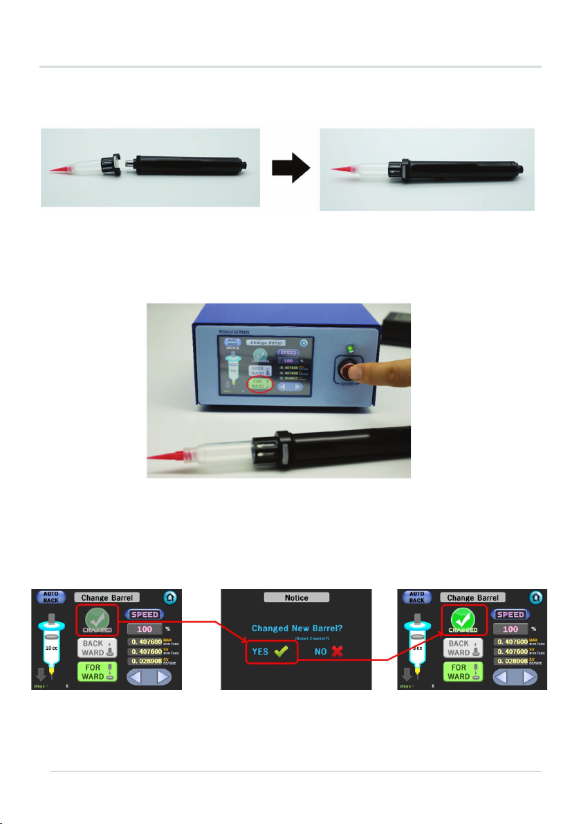
6.3.5 CHANGE SETTING
Figure 15. CHANGE SETTING
Once the Plunger has been connected, set the setting value for the CHANGED button to YES to
complete assembly of the Barrel.
Figure 13. DA 1000V Mounting Order
As shown in Figure 13, mount the Barrel and Barrel Holder (with Plunger and liquid) onto the DA 1000V.
Figure 14. Locking the Plunger using the SHOT button
After setting the DA 1000V’s direction to FORWARD, pressing the SHOT button will be that load
is reached to the Plunger which is inside of barrel.
Figure 15. CHANGE SETTING
Once the Plunger has been connected, set the setting value for the CHANGED button to YES to complete assembly of
the Barrel.
Installation and maintenance guide
NANO PENNANOPEN Operation Manual Doc. Rev 0
2019/7/2 26/47 Copyright © 2019 by TAEHA CORP. All Rights Reserved
6.4 Setting Dispensing Conditions and Discharging
Figure 16. Setting Dispensing Conditions
After setting the dispensing conditions as shown in Figure 16, set the dispensing mode as shown in
Figure 17 and execute the dispensing.
→When changing the dispensing mode, change the dispensing mode by releasing the LOCK button
at the bottom of the HOME PAGE.
Figure 17. Setting Dispensing Mode
7.4 Setting Dispensing Conditions and Discharging
NANO PENNANOPEN Operation Manual Doc. Rev 0
2019/7/2 26/47 Copyright © 2019 by TAEHA CORP. All Rights Reserved
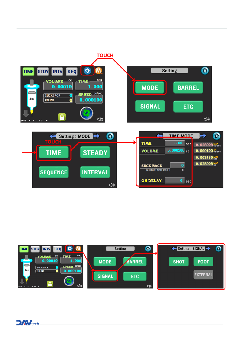
6.4 Setting Dispensing Conditions and Discharging
Figure 16. Setting Dispensing Conditions
After setting the dispensing conditions as shown in Figure 16, set the dispensing mode as shown in
Figure 17 and execute the dispensing.
→When changing the dispensing mode, change the dispensing mode by releasing the LOCK button
at the bottom of the HOME PAGE.
Figure 17. Setting Dispensing Mode
Figure 16. Setting Dispensing Conditions
After setting the dispensing conditions as shown in Figure 16, set the dispensing mode
as shown in Figure 17 and execute the dispensing.
> When changing the dispensing mode, change the dispensing mode by releasing the LOCK button
at the bottom of the HOME PAGE.
Figure 17. Setting Dispensing Mode
Table of contents
Popular Dispenser manuals by other brands

BOWMAN
BOWMAN CL003-0111 manual

SIKA
SIKA Power Cure operating instructions

Silver King
Silver King Majestic SK12MAJ Technical manual and replacement parts list

Franke
Franke F3Dn Twin Service manual

HURAKAN
HURAKAN HKN-MT1 manual

STIEBEL ELTRON
STIEBEL ELTRON UltraHot Plus Operation and installation instructions


