David Engineering & Mfg PDR UPM50 User manual
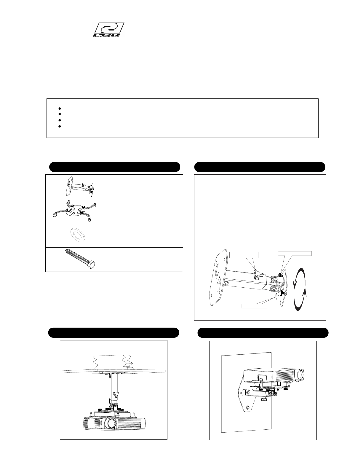
Projector ceiling mount application fig 1
Fig 1
Projector wall mounting application fig 2
Fig 2
Model
UPM50 PROJECTOR MOUNT CEILING/WALL
To ensure the correct usage, please read and follow the instructions manual thoroughly. Please store the instructions in a safe place for future reference.
To ensure customer safety, be sure to decide the installation location so that the strength is sufficient to withstand the weight of both the projector
and the mount.
Fully tighten all of the mounting screws as specified in the instructions.
1
Special techniques are necessary for installation of the panel display mount.
Do not attempt to perform this work by yourself.
Request an installation specialist to install this unit.
Manufacturer assumes absolutely no responsibility for injuries and damages that may occur due to improper installation and handling.
Please remember that if you remove the mount from the wall/ceiling later, you will find the screw holes and anchor bolts for the
mounting unit left on the wall.
All PDR mounts and adapters carry a limited lifetime warranty from ship date against defects in material and workmanship.
We are not liable for improper installation that results in damage to mounts, adapters or presentation equipment.
Mounts by
A division of David Engineering & Mfg. Inc.
A
B
Parts Configuration Chart
5/16" x 2 1/2” Lag bolts …4 pcs
D
(Note: used with the 5/16" Flat washers C).
C5/16" Flat washers…4 pcs
!Simple to adjust no tools required
!Applications for wall or ceiling mounting
!Adjustable height from 2 1/2” to 12”
(adapter req. For additional height)
!Pitch + yaw adjustments and 360 deg.
rotation
!Quick projector removal with exclusive
“Bayonet locking system”
Features
Thank you for purchasing the PDR Projector mount with the exclusive “Bayonet locking system” (patent applied for)
Universal adapter plate assembly 1pc
SEE SHEET 3 FOR INSTRUCTIONS
Projector mount 1 pc
Safety lever
Locking thumb screw
Slide adjustment
Rotate 360 deg
the strength of the wood studs is not sufficient, add reinforcement.
Always confirm the center of the stud is used for the installation.
Avoid installing in locations where the temperature and humidity are excessively high, and where contact with any
not install in locations where there are excessive amounts of dust,
Do not block the ventilation holes. Leave sufficient clearance in regard to the surroundings to avoid blocking the ventilation..
The internal temperature could elevate and possibly result in fire. Install the panel (4") or more away from surroundings.
.
Do not install in locations where there is excessive vibration or impact. Injury and damage could result from the projector mount
light. Strong light could result in eye fatigue during usage. .
Use the specified bolts and screws in the specified places and tighten firmly. Failure to do this could cause injury if the projector
could result with injury due to the projector mount falling..
.
C a u t i o n : I n s t a l l a t i o n o f u n i t i s t o b e c a r r i e d o u t b y q u a l i f i e d t e c h n i c i a n s o n l y . I n s t a l l i n a n a p p r o p r i a t e
l o c a t i o n b y c h e c k i n g t h e w a l l s t r u c t u r e a n d d u r a b i l i t y f o r s a f e t y a n d a c c i d e n t p r e v e n t i o n .
INSTALLATION LOCATION
INSTALLATION ON A WOODEN WALL
Always install so that the load is supported by a wood stud. If
Do not install on decorative posts or plaster board.
water is possible. These can result in fire or electric shock.
Do not install close to an air conditioner intake or outlet. Do
oily smoke or tobacco smoke. Fire could result. .
.
falling. .
Do not install where there is direct sunlight or other strong
mount falls. .
Do not alter any of the parts. Do not use broken parts. This
.
Note:
.
2
CAUTION
WARNING
WARNING
REV 05/10/05
The wall where the mount is to be installed must be capable of long-term support of the
total load of the projector and mount. Measures should be taken to ensure sufficient
strength to withstand the force of earthquakes , vibrations and other external forces.
Incorrect installation can cause the projector mount to fall and cause injury.
Total load of the mount ( projector + Mount)
Maximum weight - 20 Lbs ( 10Kg.)
F
G
4.3 mm x 8.9mm steel washer 4pcs
2.7mm x 6mm steel washer 4 pcs
I
H9/32” x 47/64” Nylon washer 4 pcs
J
1/4-20 x 5/8 carriage bolts 4 pcs
Leveling barrels 4 pcs
K
L
M 3 x 25mm Pan Head Philips machine Screw 4 pcs
M2.6 x 25mm Cheese Head slotted machine Screw 4 pcs
O
MM4 x 25mm Pan Head Philips machine Screw 4 pcs
P
M6 x 25mm Pan Head Philips machine Screw 4 pcs
Black plastic knob 4 pcs
Q
R
Adjustable arm (right) 2 pcs
Adjustable arm (left) 2 pcs
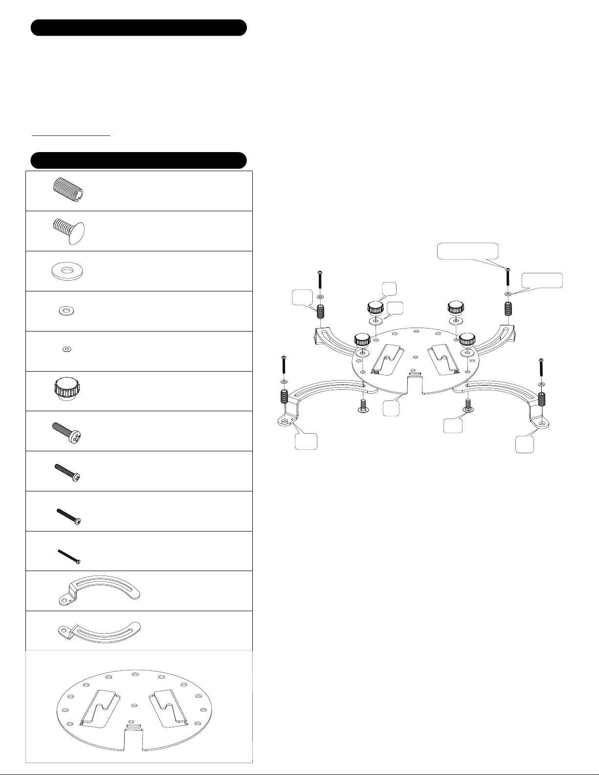
ADAPTER PLATE HARDWARE
ADAPTER PLATE ASSEMBLY
FK
H
Q
G
R
I OR J
L,M,O, OR P
S
S
Adapter plate 1 pc
1: Start by screwing the leveling barrels ( F ) into the Adjustable arm (Q and R). A screwdriver slot is provided in the barrel ( F ) .The barrels only
need to be threaded approx. 1/8 “ through the bottom of the arm (Q and R) If the mounting plane of the projector is not flat ,the barrels can be
adjusted to make up the difference in height.
2: Using the adapter plate ( S ) attach the adjustable arms ( Q,R ) with the hardware supplied (G,H,K) No need to tighten at this time.
3: Place the Universal adapter plate onto the projector. (See fig 4) Using the proper hardware supplied ( screws L,M,O or P) (washers I or J )
lightly fasten to the projector.
4: Position the universal adapter plate approx over the center of the projector, tighten the screws to the projector and then tighten the Plastic knobs
( K ). Be carful to not over tighten the projector screws. Damage to the projector may occur if the screws to the projector are over tightened.
See fig 2b for details
Fig 2b
3
Note: must be used with washer “I”
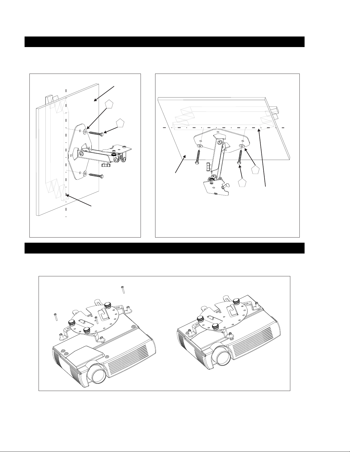
1. FASTEN THE PROJECTOR MOUNT TO WALL
Fig 3
Fig 4
NOTE: Do not over tighten the bracket mounting screws as damage to the projector’s internal mounting threads could occur.
4
The bracket must be secured to the wall studs capable of at least
you find the center of the stud. Using at least two of the four lag bolts and washers supplied secure the mounting plate to the center of the studs. Pre drill
3/16” (5mm) hole for lag bolts. Vertical and horizontal holes are provided to suite alternate mounting applications. fig.3 Shows wall mount application. fig 3b shows
ceiling mount application. Other hardware may be purchased from your local hardware supplier for hard surface mounting. Note: slide adjustment knob faces down
on the wall mount application.
(5) times the weight of the projector + mount. Locate the wall or ceiling stud using a stud finder. Insure
( D ) ( C )
Fig 3b
WALL MOUNT APPLICATION CEILING MOUNT APPLICATION
Attach the adapter plate assembly to the projector
( screws L,M,O or P) (washers I or J )
Using the proper hardware supplied
Fig 4
D
C
D
C
Centerline
of ceiling 2”x4” wood stud
Centerline of 2”x 4” wood
stud
2. ATTACH THE ADAPTER PLATE TO THE PROJECTOR.
Projector assembly
½” Wall board
½” Wall board

3. MOUNT THE PROJECTOR ASSEMBLY TO THE PROJECTOR MOUNT
Fig 5
4. Alternate height
5
Place the projector assembly into the bayonet slots on the mount ( small end into large end) and slide backward until the safety
lever engages fig 5. Adjust the thumb screws to secure the mount to the projector. To remove loosen the thumb screws and lift the
safety lever, slide the unit forward and out.
NOTE: Some of the projector mount pieces are removed for a better view.
Locking thumb screw
Safety lever
Projector assembly
Projector mount
HEIGHT ADJUST
9” - 12”
MIN HEIGHT 2 ½”
To convert to a 2 ½” length. Remove the 4 screws in fig 6. Using the 2 screws and 6 washer reassemble the unit as in fig 7.
Fig 6 Fig 7
2 washers
each side
Screw
Washer
Table of contents
Other David Engineering & Mfg Projector Accessories manuals


 installation manual")


