David White 4200H User manual

www.davidwhite.us.com
4200H
4200HV
Rotary Laser Owner’s Guide
4200H
FOR CUSTOMER SERVICE, PARTS AND REPAIR CALL
(765) 581-4097
IMPORTANT: IMPORTANT: IMPORTANTE:
Read Before Using Lire avant usage Leer antes de usar
180°
10°
45°
90°
RPM
4200HV

-2-
With David White
your sights are set on
precision and accuracy.
Congratulations! You’ve purchased a David White builder/contractor
instrument, known throughout the world for precision and accuracy.
The purpose of this user’s guide is to acquaint you with the instrument, its
components, safety, proper care and handling.
Our levels, level-transits and transits are constructed to withstand
extremely rugged field use. Like all precision instruments, however, they
should be treated with reasonable care to prolong life and accuracy.
All instruments are adjusted when they are shipped from the factory. It
is the customer’s responsibility to check and to ensure instruments are
adjusted prior to using.
David White is not responsible for errors caused by instruments that are
out of adjustment.
Contact your distributor, dealer or David White for information on the
nearest facility to check if your instrument is properly adjusted.
All specifications are subject to change without notice.
-3-
180°
10°
45°
90°
RPM
4200HV
8 7
180°
10°
45°
90°
RPM
4200HV
f
d
eh
g
b
a
c
1
2
3
4
6
5

-4-
4200H
4200H
1
2
3
4
6
5
d
b
a
c

-5-
GENERAL SAFETY RULES
!WARNING Read all instructions. Failure to follow all instructions listed
below may result in hazardous radiation exposure, electric
shock, fire and/or serious injury.
If glass light house breaks when dropped, contact customer service
immediately. Broken glass can cause laceration hazard and unit to
lose its IP rating.
IEC 60825-1:2007-03
<
1 mW, 635 nm
DO NOT direct the laser beam at persons or animals and do not
stare into the laser beam yourself. This tool produces laser class 2
laser radiation and complies with 21 CFR 1040.10 and 1040.11
except for deviations pursuant to Laser Notice No. 50, dated June
24, 2007. This can lead to persons being blinded.
DO NOT remove or deface any warning or caution labels.
Removing labels increases the risk of exposure to laser radiation.
Use of controls or adjustments or performance of procedures other than those
specified in this manual, may result in hazardous radiation exposure.
ALWAYS make sure that any bystanders in the vicinity of use are made aware
of the dangers of looking directly into the laser tool.
DO NOT place the laser tool in a position that may cause anyone to stare into
the laser beam intentionally or unintentionally. Serious eye injury could result.
ALWAYS position the laser tool securely. Damage to the laser tool and/or
serious injury to the user could result if the laser tool falls.
ALWAYS use only the accessories that are recommended by the manufacturer
of your laser tool. Use of accessories that have been designed for use with
other laser tools could result in serious injury or unsatisfactory performance.
DO NOT use this laser tool for any purpose other than those outlined in this
manual. This could result in serious injury or unsatisfactory performance.
DO NOT leave the laser tool “ON” unattended in any operating mode.
DO NOT disassemble the laser tool. There are no user serviceable parts inside.
Do not modify the product in any way. Modifying the laser tool may result in
hazardous laser radiation exposure.

-6-
Work area safety
Keep work area clean and well
lit. Cluttered or dark areas invite
accidents.
DO NOT operate the laser tool around
children or allow children to operate
the laser tool. Serious eye injury
could result.
DO NOT use instruments, attachments
and accessories outdoors when
lightening conditions are present.
Electrical safety
Batteries can explode or leak, cause
injury or fire. To reduce this risk,
always follow all instructions and
warnings on the battery label and
package.
Remove the batteries from the tool
when not using it for extended
periods. When storing for extended
periods, the batteries can corrode
and discharge themselves.
DO NOT short any battery terminals.
DO NOT charge alkaline batteries.
DO NOT mix old and new batteries.
Replace all old batteries at the same
time with new batteries of the same
brand and type.
DO NOT mix battery chemistries.
Dispose of or recycle batteries per
local code.
DO NOT dispose of batteries in fire.
Keep batteries out of reach of
children.
Personal safety
Stay alert, watch what you are
doing and use common sense
when operating a tool. Do not use
a tool while you are tired or under
the influence of drugs, alcohol or
medication. A moment of inattention
while operating a tool may result in
serious personal injury or incorrect
measurement results.
Use safety equipment. Always wear
eye protection. Safety equipment
such as dust mask, non-skid
safety shoes, hard hat, or hearing
protection used for appropriate
conditions will reduce personal
injuries.
DO NOT use the laser viewing glasses
as safety goggles. The laser viewing
glasses are used for improved
visualization of the laser beam, but
they do not protect against laser
radiation.
DO NOT use the laser viewing glasses
as sun glasses or in traffic. The
laser viewing glasses do not afford
complete UV protection and reduce
color perception.
DO NOT use any optical tools such
as, but not limited to, telescopes

-7-
or transits to view the laser beam.
Serious eye injury could result.
DO NOT stare directly at the laser
beam or project the laser beam
directly into the eyes of others.
Serious eye injury could result.
Use caution when using instruments
in the vicinity of electrical hazards.
Magnets
IEC 60825-1:2007-03
<
1 mW, 635 nm
Keep the tool and laser
target away from cardiac
pacemakers. The magnets
of the tool and laser target
plate generate a field that can impair
the function of cardiac pacemakers.
Keep the tool and laser target away
from magnetic data medium and
magnetically-sensitive equipment.
The effect of the magnets of the tool
and laser target plate can lead to
irreversible data loss.
Use and care
Use the correct tool for your
application. The correct tool will do
the job better and safer.
Do not use the tool if the switch does
not turn it on and off. Any tool that
cannot be controlled with the switch
is dangerous and must be repaired.
Store idle tool out of the reach of
children and do not allow persons
unfamiliar with the tool or these
instructions to operate the tool.
Tools are dangerous in the hands of
untrained users.
Maintain tools. Check for
misalignment or binding of moving
parts, breakage of parts and any
other condition that may affect the
operation. If damaged, repair tool
before use. Many accidents are
caused by poorly maintained tools.
Use the tool, accessories, etc., in
accordance with these instructions
and in the manner intended for the
particular type of tool, taking into
account the working conditions and
the work to be performed. Use of
the tool for operations different from
those intended could result in a
hazardous situation.
SAVE THESE INSTRUCTIONS.
INTENDED USE
The instrument is intended for determining and checking precise horizontal
and vertical (4200HV only) lines. The instrument is suitable for indoor and
outdoor use.

-8-
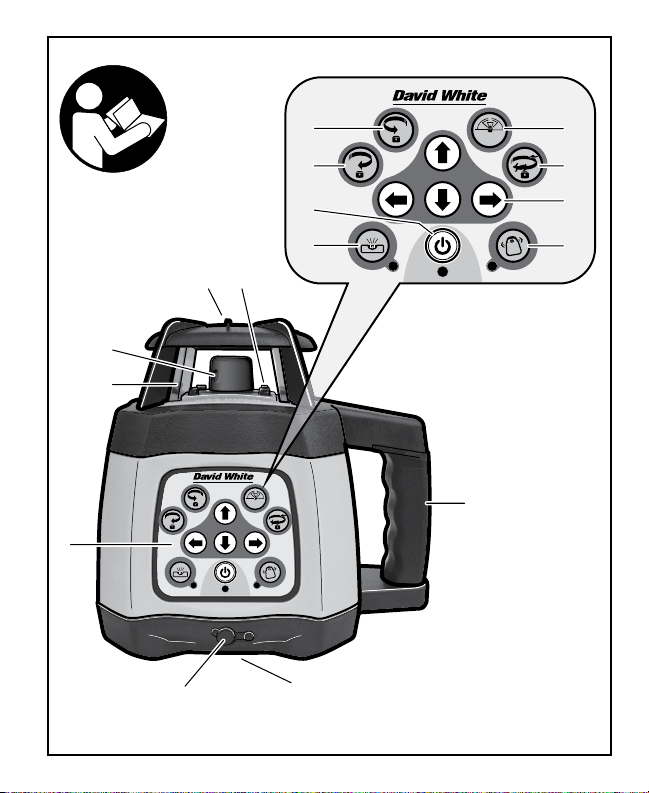
FEATURES
The numbering of the product
features shown refers to the
illustration of the instrument on the
graphic page.
1. Rotating Laser Beacon
2. Glass Lighthouse
3. Control Keypad
3a. On/Off button with Indicator
3b. Manual Mode Button with
Indicator
3c. ADS button with Indicator
3d. Slope Adjustment Buttons
3e. Variable Rotation Speed Button
3f. Scanning Angle Button
3g. Counter-Clockwise Beam
Positioning Button
3h. Clockwise Beam Positioning
Button
4. Charger Port
5. 5/8-11 Tripod Mount, Down
Plumb Beam (4200HV)
6. Carrying Handle
7. Reception Sensors for Remote
Control
8. Window for Plumb Beam
TECHNICAL DATA
Description 4200H 4200HV
Accuracy, Horizontal leveling 1/8-in at 100-ft
(3mm at 30m)
1/8-in at 100-ft
(3mm at 30m)
Accuracy, Vertical/Laydown n/a 1/8-in at 100-ft
(3mm at 30m)
Working Range (diameter)
- without Laser Detector, approx.
- with Laser Detector, apprx.
1600-ft (500m)
100-ft (30m)
1600-ft (500m)
Rotational Speed 600 RPM 0, 60, 300, 600 RPM
Leveling Type (Degrees) Electronic (±5º) Electronic (±5º)
Beam Rating Class 2M 650nm Class 2M 650nm

-9-
PREPARATIONS
Description 4200H 4200HV
Slope/Grade Capability Dual (±10.00%) Dual (±10.00%)
Power Supply 4-C Cell, NiMh
Rechargeable Approx.
50hr.(Ni-MH);
Approx. 40hr (Alkaline)
4-C Cell, NiMh
Rechargeable Approx.
50hr.(Ni-MH);
Approx. 40hr (Alkaline)
Water/Dust Protection IP55 IP55
Dimension 6.3 x 6.3 x 7.8-in
(160 x 160 x 198mm)
6.3 x 6.3 x 7.8-in
(160 x 160 x 198 mm)
Weight: 4.5 lb (2.0kg) 4.5 lb (2.0kg)
Inserting/Replacing Battery
Rechargeable or alkaline battery
packs are suitable for use to power
your instrument.
!WARNING Always replace all
alkaline batteries at
the same time. Only use batteries
from one brand and with the identical
capacity.
Remove the batteries/pack from the
tool when not using it for extended
periods. When storing for extended
periods, the batteries can corrode and
discharge themselves.
Un-screw the bolt at the bottom of
instrument base. Remove the battery
pack.
Use either alkaline battery or Ni-Mh
battery pack. When inserting
alkaline batteries, pay attention to
the correct polarity according to the
representation on the inside of the
battery compartment. Always replace
all batteries at the same time. Only
use batteries from one brand and
with the identical capacity.
When installing the battery pack
onto base, be certain that electrode
connection align properly. Secure by
tighten the bolt onto the bottom of
instrument base.
Remove the batteries from the
tool when not using it for extended
periods. When storing for extended
periods, the batteries can corrode
and discharge themselves.

-10-
OPERATION
Charging Rechargeable
NiMh Battery Pack
Insert the charger into the outlet and
the charging port of the instrument
or the battery pack. The charger LED
will display 1 of 3 modes:
1. Red flashing light - Battery NOT
Charging. Check connections
2. Red light - Battery Charging
Take up to 7 hrs to fully charge
3. Green light - Battery Fully
Charged. Ready for Use
When using the standard
rechargeable batteries of the
instrument, recharging takes up
to 8 hours (4 x 5000 mAh Ni-Mh
batteries).
Power required for the charger:
Frequency: 50-60HZ; Voltage:
85-265V.
Instrument can be used while
charging rechargeable battery pack.
Brand-new rechargeable batteries
or rechargeable batteries unused for
long period need to be recharged
and discharged three times to attain
full capacity.
!WARNING Do not subject the
instrument to
extreme temperatures or variations in
temperature. As an example, do not
leave it in vehicles for long time. In
case of large variations in
temperature, allow the instrument to
adjust to the ambient temperature
before putting it into operation. In
case of extreme temperatures or
variations in temperature, the
accuracy of the instrument can be
impaired.
Avoid heavy impact to or falling
down of the instrument. After severe
exterior effects to the instrument,
it is recommended to carry out an
accuracy check each time before
continuing to work.
Setting Up the Instrument
Position the instrument on a firm
surface in the horizontal or vertical
(4200HV) position, mount it to a
tripod or to the wall mount with
alignment unit. Due to the high
leveling accuracy, the instrument
reacts sensitively to ground vibrations
and position changes. Therefore,
pay attention that the position of
the instrument is stable in order to
avoid operational interruptions due to
re-leveling.

-11-
OPERATION MODES
Switching On and Off
Press the Power ON/OFF 3a keypad
and allow the laser instrument to
self-level. If the power indicator LED
blinks, the voltage of the batteries
is low and batteries need to be
replaced or recharged.
The laser instrument can stand
alone on a level, sturdy surface
or preferably secured to a 5/8-11
tripod.
When the instrument is powered ON
it will automatically self-level. After
self-leveling, the laser instrument will
begin operating in Rotation Mode at
the speed of 600 RPM.
If the instrument is placed improperly,
or the slope of instrument exceeds
the range of +/-5°, the Power
indicator LED and the laser beam will
blink at the same time.
The instrument will shut down
automatically if the unit exceeds the
self-leveling system range for more
then 5 minutes.
Variable Rotation Speed
(4200HV Only)
The Variable Rotation Speed Mode
keypad 3e will give you the option of
increasing or decreasing the speed
of the rotating laser. Repeatedly
pressing the
180°
10°
45°
90°
RPM
keypad will adjust
the speed from 600, 300, 150, and
0 RPM.
Scanning or Sweeping
(4200HV Only)
The Scanning Mode 3f creates a
shorter, brighter laser “chalk line” that
can be used for leveling or plumbing.
This feature can also be used to
keep the instrument from interfering
with other lasers and detectors on
site. Pressing the Scanning Mode
keypad
180°
10°
45°
90°
RPM
, will lengthen or shorten
the scan area of the laser beam.
While in Scanning Mode, the
position of the scanning area can be
adjusted. Press the Clock-Wise 3h
180°
10°
45°
90°
RPM
and Counter-Clock-Wise 3g
180°
10°
45°
90°
RPM
Beam Positioning keypads.
Slope/Grade Mode
When the instrument is set upright for
horizontal rotation, the slope of the
X-axis and Y-axis can be adjusted
by using Manual Mode 3b. Press the
Manual/Automatic keypad
180°
10°
45°
90°
RPM
, the
instrument will enter into the mode of
manual adjustment.

-12-
X
1X
2
Y1
Y2
180°
10°
45°
90°
RPM
4200HV
Slope of X-axis
Aim the X1-beam to the direction of
the slope required.
Press the slope adjustment buttons
180°
10°
45°
90°
RPM
or
180°
10°
45°
90°
RPM
to move the laser beam
up or down until the beam slope is
set at the desired position.
Slope of Y-axis
Aim the Y1-beam towards the
direction of slope required. Press
the slope adjustment buttons
180°
10°
45°
90°
RPM
or
180°
10°
45°
90°
RPM
to position the laser beam up or
down until the beam slope is set at
the desired position.
To return to automatic Self-Leveling
Mode, press the Manual/Automatic
3b keypad again. Allow time for the
instrument to self-level.
Smart H.I. Alert System (ADS)
Enable to the ADS system 3c to alert
user when laser has been disturbed.
Press the ADS button
180°
10°
45°
90°
RPM
to activate.
When the LED is blinking slowly, the
laser is in H.I Alert mode. When the
light is blinking quickly, the laser level
will not level as it has been disturbed
and needs reset.
Vertical Laydown Positioning
(4200HV Only)
Place the laser instrument in the
laydown position on a flat, level
surface.
Press the Power ON/OFF keypad.
Allow the instrument to self-level.
-13-
ACCURACY CHECK
The ambient temperature has
the greatest influence. Especially
temperature differences occurring
from the ground upward can divert
the laser beam. The deviations play a
role in excess of approx. 65-ft (20m)
measuring distance and can easily
reach two to four times the deviation
at 330-ft (100m). Because the largest
difference in temperature layers is
close to the ground, the instrument
should always be mounted on a
tripod when measuring distances
exceeding 65-ft (20m). If possible,
also set up the instrument in the
center of the work area.
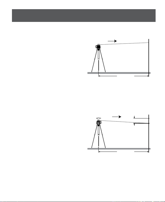
Checking the Leveling Accuracy
Apart from exterior influences,
device-specific influences (such as
heavy impact or falling down) can
lead to deviations. Therefore, check
the accuracy of the instrument each
time before starting your work. A
free measuring distance of 165-ft
(50m) on a firm surface is required for
the check. A reversal measurement
must be carried out over both axes X
and Y (each positive and negative; 4
complete measurements).
– Mount the instrument in the
horizontal position onto a tripod or
place it on a firm and level surface
near wall. Switch the instrument
on. Position the X-axis to aim to a
wall or target plate.
165-ft (50 m)
H1
Y1
165-ft (50 m)
H1
H2
Y2
100-ft (30 m)
1.5-ft
(0.5 m)
A
H1
B
100-ft (30 m)
1.5-ft
(0.5 m)
A
H1 H2
B
100-ft (30 m) 1.5-ft
(0.5 m)
A
H1
D
H3 H2
B
100-ft (30 m) 1.5-ft
(0.5 m)
A
H1 H2
B
D
180°
165-ft (50 m)
H1
X1
165-ft (50 m)
H1
H2
X2
D
180°
180°
180°
180°
10°
45°
90°
RPM
4250HV
–
After the leveling, mark the center of
the laser beam on wall (point H1).
– Rotate the instrument by 180°,
allow it to level in and mark the
center point of the laser beam on
the wall (point H2).
165-ft (50 m)
H1
Y1
165-ft (50 m)
H1
H2
Y2
100-ft (30 m)
1.5-ft
(0.5 m)
A
H1
B
100-ft (30 m)
1.5-ft
(0.5 m)
A
H1 H2
B
100-ft (30 m) 1.5-ft
(0.5 m)
A
H1
D
H3 H2
B
100-ft (30 m) 1.5-ft
(0.5 m)
A
H1 H2
B
D
180°
165-ft (50 m)
H1
X1
165-ft (50 m)
H1
H2
X2
D
180°
180°
180°
180°
10°
45°
90°
RPM
4250HV
– The difference Dof both marked
points H1 and H2 on wall is the
actual deviation of the instrument
for the measured axis.
The value of D(deviation) should be
less than 5/16-in (8mm).
-14-
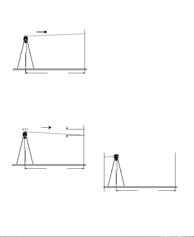
Repeat the measuring procedure for
the Y-axis. Position the Y-axis to aim
to a wall or target plate.
165-ft (50 m)
H1
Y1
165-ft (50 m)
H1
H2
Y2
100-ft (30 m)
1.5-ft
(0.5 m)
A
H1
B
100-ft (30 m)
1.5-ft
(0.5 m)
A
H1 H2
B
100-ft (30 m) 1.5-ft
(0.5 m)
A
H1
D
H3 H2
B
100-ft (30 m) 1.5-ft
(0.5 m)
A
H1 H2
B
D
180°
165-ft (50 m)
H1
X1
165-ft (50 m)
H1
H2
X2
D
180°
180°
180°
180°
10°
45°
90°
RPM
4250HV
– After the leveling, mark the center
of the laser beam on wall (point
H1).
– Rotate the instrument by 180°,
allow it to level in and mark the
center point of the laser beam on
the wall (point H2).
165-ft (50 m)
H1
Y1
165-ft (50 m)
H1
H2
Y2
100-ft (30 m)
1.5-ft
(0.5 m)
A
H1
B
100-ft (30 m)
1.5-ft
(0.5 m)
A
H1 H2
B
100-ft (30 m) 1.5-ft
(0.5 m)
A
H1
D
H3 H2
B
100-ft (30 m) 1.5-ft
(0.5 m)
A
H1 H2
B
D
180°
165-ft (50 m)
H1
X1
165-ft (50 m)
H1
H2
X2
D
180°
180°
180°
180°
10°
45°
90°
RPM
4250HV
– The difference Dof both marked
points H1 and H2 on wall is the
actual deviation of the instrument
for the measured axis.
The value of D(deviation) in either
axis should be less than 5/16-in
(8mm).
If the instrument should exceed
the maximum deviation in anyone
of the measuring procedures, have
it checked at a SitePro after-sales
service agent.
Checking the Vertical Alignment
(4200HV Only)
A free measuring distance of 100-ft
(30m) on a firm surface between two
walls or targets Aand Bis required
for the check.
Place the laser instrument in the
laydown position on a flat, level
surface.
– Mount the instrument in the
vertical position onto a tripod using
mount accessory or place it on a
firm and level surface near wall.
– Switch the instrument on. Position
the up beam to aim at wall Aor
target plate.
165-ft (50 m)
H1
Y1
165-ft (50 m)
H1
H2
Y2
100-ft (30 m)
1.5-ft
(0.5 m)
A
H1
B
100-ft (30 m)
1.5-ft
(0.5 m)
A
H1 H2
B
100-ft (30 m) 1.5-ft
(0.5 m)
A
H1
D
H3 H2
B
100-ft (30 m) 1.5-ft
(0.5 m)
A
H1 H2
B
D
180°
165-ft (50 m)
H1
X1
165-ft (50 m)
H1
H2
X2
D
180°
180°
180°
180°
10°
45°
90°
RPM
4250HV
–
After the leveling, mark the center of
the laser beam on wall A(point H1).
– Rotate the instrument by 180°
(without changing the height),
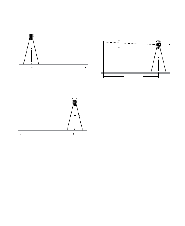
-15-
allow it to level and mark the
center point of the laser beam on
wall
B
(point H2).
165-ft (50 m)
H1
Y1
165-ft (50 m)
H1
H2
Y2
100-ft (30 m)
1.5-ft
(0.5 m)
A
H1
B
100-ft (30 m)
1.5-ft
(0.5 m)
A
H1 H2
B
100-ft (30 m) 1.5-ft
(0.5 m)
A
H1
D
H3 H2
B
100-ft (30 m) 1.5-ft
(0.5 m)
A
H1 H2
B
D
180°
165-ft (50 m)
H1
X1
165-ft (50 m)
H1
H2
X2
D
180°
180°
180°
180°
10°
45°
90°
RPM
4250HV
– Without turning the instrument,
position it close to wall Bby
moving the tripod.
165-ft (50 m)
H1
Y1
165-ft (50 m)
H1
H2
Y2
100-ft (30 m)
1.5-ft
(0.5 m)
A
H1
B
100-ft (30 m)
1.5-ft
(0.5 m)
A
H1 H2
B
100-ft (30 m) 1.5-ft
(0.5 m)
A
H1
D
H3 H2
B
100-ft (30 m) 1.5-ft
(0.5 m)
A
H1 H2
B
D
180°
165-ft (50 m)
H1
X1
165-ft (50 m)
H1
H2
X2
D
180°
180°
180°
180°
10°
45°
90°
RPM
4250HV
–
After instrument levels, align the
height of the instrument so that the
center point of laser beam is exactly
on point
H2
of wall
B
.
– Rotate the instrument by 180°
(without changing the height),
allow it to level and mark the
center point of the laser beam on
wall
A
(point H3).
– The mark of p
oint H3 should be
marked in such a way that it is as
vertical as possible (above or below)
of point H1.
165-ft (50 m)
H1
Y1
165-ft (50 m)
H1
H2
Y2
100-ft (30 m)
1.5-ft
(0.5 m)
A
H1
B
100-ft (30 m)
1.5-ft
(0.5 m)
A
H1 H2
B
100-ft (30 m) 1.5-ft
(0.5 m)
A
H1
D
H3 H2
B
100-ft (30 m) 1.5-ft
(0.5 m)
A
H1 H2
B
D
180°
165-ft (50 m)
H1
X1
165-ft (50 m)
H1
H2
X2
D
180°
180°
180°
180°
10°
45°
90°
RPM
4250HV
The difference Dof both marked
points H1 and H3 on wall Ais the
actual deviation of the instrument for
the measured axis.
The value of D(deviation) should be
less than 3/16-in (4mm).
If the instrument should exceed
the maximum deviation in anyone
of the measuring procedures, have
it checked at a SitePro after-sales
service agent.
-16-
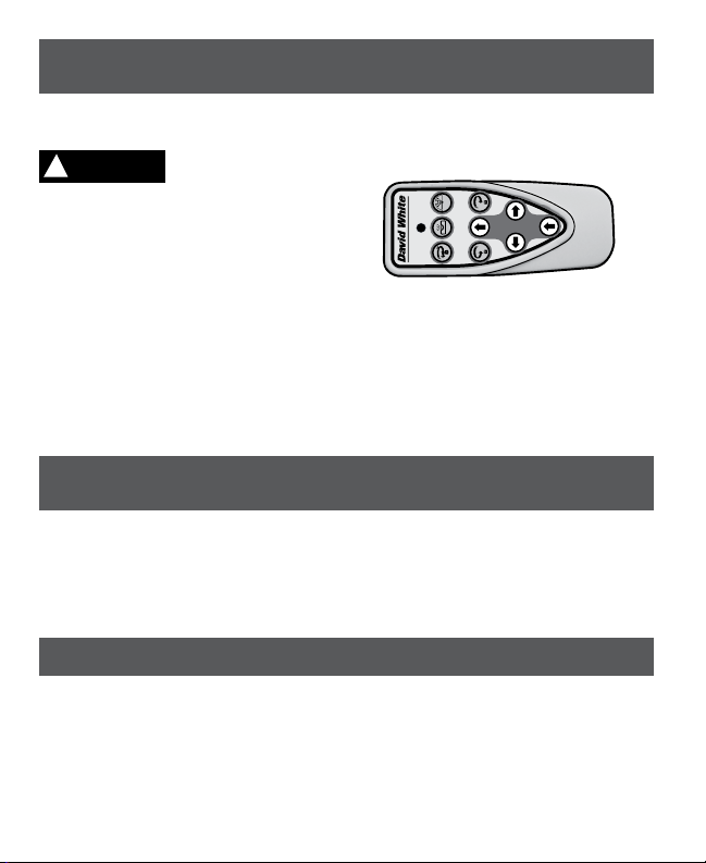
The 4200HV includes a remote
control.
!WARNING Have the remote
control repaired
only through a qualified repair person
and only using identical replacement
parts. This will ensure that the
functionality of the remote control is
maintained.
Do not operate the remote control in
explosive atmospheres, such as in
the presence of flammable liquids,
gases or dusts. Sparks can be
created in the remote control which
may ignite the dust or fumes.
The remote control can be used
up to a maximum of 100 feet (30m)
away from the instrument.
The remote must be pointed
towards the instrument for proper
operation. All the features of the
4200HV can be controlled using the
remote.
Requires 2 ‘AA’ Alkaline batteries.
RC420 REMOTE CONTROL
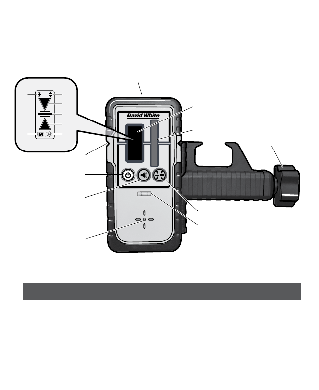
LD20 DETECTOR
The detector aids in locating and targeting a visible or invisible beam emitted by
a rotary laser instrument; perfect for use in outdoor conditions, where sunlight
and distance may make locating the beam more difficult.
The laser detector includes a rod clamp which allows to mount the detector
onto square, round or oval sighting rods.
The numbering of the product
features shown refers to the
illustration of the tool above.
1. On/Off switch
2. Center mark
3. LCD Display
3a. “Fine” adjustment indicator
3b. “Coarse” adjustment indicator
3c. Direction indicator “move
downward”
3d. Center indicator
3e. Direction indicator “move upward”
LD20
RC420
RPM
180°
10°
45°
90°
4
9
10
5
6
3
2
1
8
7
c
b
e
fg
a
d
LD20 FEATURES
-17-
LD20
RC420
RPM
180°
10°
45°
90°
4
9
10
5
6
3
2
1
8
7
c
b
e
fg
a
d
Inserting/Replacing the Battery
9V alkaline battery is recommended
for the tool. Pull the latch of battery lid
outward and open the battery lid.
When the batteries are low, the
battery low indicator gwill display.
Remove the battery when not using it
for extended periods. When storing
for extended periods, the battery can
corrode and discharge.
3f. Audio signal indicator
3g. Battery low indicator
4. Reception area for the laser beam
5. Button for adjustment of measuring
accuracy
6. Spirit level
7. Speaker
8. Audio signal button
9. Locking screw for leveling rod
10. Magnetic mounts
LD20 PREPARATIONS

-18-
LIMITED WARRANTY
Dave White’s SitePro (“Seller”) warrants to the original purchaser only, that
all David White laser tools and optical instruments will be free from defects in
material or workmanship for a period of two (2) years from date of purchase.
SELLER’S SOLE OBLIGATION AND YOUR EXCLUSIVE REMEDY under
this Limited Warranty and, to the extent permitted by law, any warranty or
condition implied by law, shall be the repair or replacement of parts, without
charge, which are defective in material or workmanship and which have not
been misused, carelessly handled, or misrepaired by persons other than
Store and transport the tool only in
the supplied protective case.
Keep the tool clean at all times.
Do not immerse the tool into water or
other fluids.
Wipe off debris using a moist and soft
cloth. Do not use any cleaning agents
or solvents.
Regularly clean the surfaces at the
exit opening of the laser in particular,
and pay attention to any fluff of fibers.
If the tool should fail despite the care
taken in manufacturing and testing
procedures, repair should be carried
out by an authorized after-sales
service center for Dave White’s SitePro
instruments.
In all correspondence and spare parts
orders, please always include the
model number and serial number of
the instruments.
All precision instruments should
be cleaned, lubricated, checked
and adjusted ONLY at a qualified
instrument repair station or by the
manufacturer, at least once a year.
In case of repairs, send in the
instrument packed in its protective
case.
ENVIRONMENT PROTECTION
Recycle raw materials
& batteries instead of
disposing of waste.
The unit, accessories,
packaging & used
batteries should be
sorted for environmentally friendly
recycling in accordance with the
latest regulations.
MAINTENANCE AND SERVICE

-19-
Seller or Authorized Service Center. To make a claim under this Limited
Warranty, you must return the complete laser, optical instrument or David
White product, transportation prepaid, to SITEPRO Service Department or
Authorized Service Center. Please include a dated proof of purchase with your
tool. For locations of nearby service centers, please call 1-855-354-9881.
THIS LIMITED WARRANTY DOES NOT APPLY TO ACCESSORY ITEMS
SUCH AS TRIPODS, RODS, HAND LEVELS, FIELD SUPPLIES, TAPES,
MOUNTING DEVICES AND OTHER RELATED ITEMS. THESE ITEMS
RECEIVE A 90 DAY LIMITED WARRANTY.
To make a claim under this Limited Warranty, you must return the complete
product, transportation prepaid. For details to make a claim under this
Limited Warranty please visit www.davidwhite.com or call 1-855-354-9881.
ANY IMPLIED WARRANTIES SHALL BE LIMITED IN DURATION TO ONE
YEAR FROM DATE OF PURCHASE. SOME STATES IN THE U.S., AND
SOME CANADIAN PROVINCES DO NOT ALLOW LIMITATIONS ON HOW
LONG AN IMPLIED WARRANTY LASTS, SO THE ABOVE LIMITATION MAY
NOT APPLY TO YOU.
IN NO EVENT SHALL SELLER BE LIABLE FOR ANY INCIDENTAL OR
CONSEQUENTIAL DAMAGES (INCLUDING BUT NOT LIMITED TO
LIABILITY FOR LOSS OF PROFITS) ARISING FROM THE SALE OR USE
OF THIS PRODUCT. SOME STATES IN THE U.S., AND SOME CANADIAN
PROVINCES DO NOT ALLOW THE EXCLUSION OR LIMITATION OF
INCIDENTAL OR CONSEQUENTIAL DAMAGES, SO THE ABOVE
LIMITATION MAY NOT APPLY TO YOU.
THIS LIMITED WARRANTY GIVES YOU SPECIFIC LEGAL RIGHTS, AND
YOU MAY ALSO HAVE OTHER RIGHTS WHICH VARY FROM STATE
TO STATE IN THE U.S., OR PROVINCE TO PROVINCE IN CANADA AND
FROM COUNTRY TO COUNTRY.
THIS LIMITED WARRANTY APPLIES ONLY TO PRODUCTS SOLD WITHIN
THE UNITED STATES OF AMERICA, CANADA AND THE COMMONWEALTH
OF PUERTO RICO. FOR WARRANTY COVERAGE WITHIN OTHER
COUNTRIES, CONTACT YOUR LOCAL SITEPRO DEALER OR IMPORTER.
David White is a registered trademark and offered exclusively by SitePro.

42348D4200 09/15 Printed in China
© Dave White’s SitePro 7619 S 1150 E Otterbein, IN 47970
Tel. +1 (765) 581 4097
This manual suits for next models
1
Table of contents
Other David White Laser Level manuals


