David White AL8-26 User manual
AL8- Series Owner’s Guide
www.davidwhite.com
FOR CUSTOMER SERVICE, PARTS
AND REPAIR CALL
(765) 581-4097
IMPORTANT: IMPORTANT : IMPORTANTE:
Read Before Using Lire avant usage Leer antes de usar
AL8-26
AL8-32

-2-
With David White
your sights are set on
precision and accuracy.
Congratulations! You’ve purchased a David White builder/contractor instrument,
known throughout the world for precision and accuracy.
The purpose of this user’s guide is to acquaint you with the instrument, its
components, safety, proper care and handling.
Our levels, level-transits and transits are constructed to withstand extremely
rugged field use. Like all precision instruments, however, they should be treated
with reasonable care to prolong life and accuracy.
All instruments are adjusted when they are shipped from the factory. It is the
customer’s responsibility to check and to ensure instruments are adjusted prior
to using.
David White is not responsible for errors caused by instruments that are out of
adjustment.
Contact your distributor, dealer or David White for information on the nearest
facility to check if your instrument is properly adjusted.
All specifications are subject to change without notice.

-3-
13
5
10
11
13
12
9
14
7
15
16
1
15
13
8
4
2
3
17
18
19
6

-4-
GENERAL SAFETY RULES
!WARNING Read all instructions. Failure to follow all instructions listed below
may result in serious injury.
!WARNING When moving a tripod-mounted instrument, handle with care. Carry
only in an upright position. Do not carry over your shoulder or in a
horizontal position. Improper handling may result in instrument damage
Handle the instrument by its base when removing from the case or attaching to a tripod.
Never use force on any parts of the instrument. All moving parts will turn freely and easily
by hand.
Check the leveling and indication accuracy of the instrument each time before using and
after longer transport of the instrument.
Protect the instrument against moisture and direct sun light.
Do not subject the instrument to extreme temperatures or variations in temperature.
As an example, do not leave it in vehicles for long time. In case of large variations in
temperature, allow the instrument to adjust to the ambient temperature before putting
it into operation. In case of extreme temperatures or variations in temperature, the
accuracy of the instrument can be impaired.
Avoid any impact to or dropping of the instrument. After severe exterior effects to
the instrument, it is recommended to carry out an accuracy check each time before
continuing to work.
Place the instrument in the provided case when transporting it over larger distances
(e.g. in the car). Ensure that the instrument is correctly placed in the transport case.
When placing the instrument in the case.
When carrying instrument, always remove the instrument from the tripod when
transporting or carrying it at the jobsite. If the instrument must be carried on the tripod,
hold the instrument as vertically as possible and keep it in front of you. Never carry the
instrument horizontally over your shoulder.
When transporting instrument long distances, always place in the carrying case.
SAVE THESE INSTRUCTIONS
INTENDED USE
The AL8- series is intended for determining and checking precise horizontal partitions.
It is also suitable for measuring heights, distances and angles.

-5-
FEATURES
The numbering of the product features
shown refers to the illustration of the
instrument on the graphic page.
1Objective lens
2Optical peep sight
3Bubble vial mirror
4Lens sunshade
5Eyepiece cover
6Adjusting screw for sighting line
7Eyepiece
8Circular bubble vial
9Compensator lock
10 Horizontal circle reference mark
11 Horizontal circle
12 Adjusting screw of circular bubble vial
13 Levelling screw
14 Tripod mount 5/8” (on the rear side)
15 Horizontal drive screw
16 Focusing knob
17 Allen key
18 Adjusting pin
19 Plumb-bob
TECHNICAL DATA
AL8-Series AL8-26 AL8-32
Accuracy: 1/16”@100’
(1.6mm at 30m)
1/32”@100’
(1.0mm at 30m)
Working Range: 300’
(90m)
400’
(120m)
Clear obj. aperture: 1.4” (36 mm) 1.6” (40mm)
Setting accuracy: +/- 0.8” +/- 0.3”
Deviation for 1 km double-run
leveling
1.5 mm 1.0 mm
Telescope:
Magnification: 26 x 32 x
Image: Erect Erect
Length: 8.3” (210 mm) 8.3” (210 mm)
Shortest focusing distance: 1’ (0.3m) 1’ (0.3m)
Field of view : 1° 30’ 1° 30’
Stadia ratio: 100 100
Compensator:
Leveling range: ±15’ ±15’
Magnet dampening: Yes Yes
Sensitivity of bubble: 8’/2mm 8’/2mm

-6-
OPERATION
Initial Operation
Check the leveling and indication accuracy
of the instrument each time before
using and after longer transport of the
measuring tool.
!WARNING Protect the instrument
against moisture and
direct sun light.
Do not subject the instrument to extreme
temperatures or variations in temperature.
As an example, do not leave it in vehicles
for long time. In case of large variations
in temperature, allow the instrument
to adjust to the ambient temperature
before putting it into operation. In case
of extreme temperatures or variations
in temperature, the accuracy of the
instrument can be impaired.
Avoid heavy impact or falling of the
instrument. After heavy exterior impact on
the instrument, an accuracy check should
always be carried out before continuing
to work.
Setting Up Instrument
!WARNING It is important that the
tripod is set up firmly.
Make sure that the tripod points are well
into the ground. On paved surfaces, be
sure the points hold securely.
The legs should have about a 3-1/2 foot
spread, positioned so the top of the tripod
head appears level.
If using a tripod with adjustable legs, be
sure the leg clamps are securely hand
tightened.
Attach the instrument to the tripod
securely, hand tightening the instrument
base to the 5/8-11 tripod head.
Aligning the Instrument
Align the instrument with the levelling
screws 13 so that the air bubble is
positioned in the centre of the circular
bubble vial 8.
Turn the first two leveling screws Aand B
to move the air bubble so that it is centred
between the two levelling screws.
Then turn the third leveling screw Cuntil
the air bubble is positioned in the centre
AL8-Series AL8-26 AL8-32
Horizontal Circle:
Diameter 4.3” (108 mm) 4.3” (108 mm)
Circle graduation: 1° 1°
Instrument weight: 3.7 lb (1.7kg) 3.7 lb (1.7kg)
Mounting thread: 5/8-11 5/8-11
Protection IP54 IP54

-7-
of the circular bubble vial.
Any remaining deviation of the instrument
to the horizontal plane following the
balancing of the circular bubble vial
is compensated by means of the
compensator.
While working, regularly check (e.g. by
viewing through the bubble vial mirror 3)
whether the air bubble is still in the centre
of the circular bubble vial.
Setting Up Over a Point
!WARNING Never use force on any
parts of the instrument.
All moving parts will turn freely and easily
by hand.
Hang the plumb bob 19, attach cord to
the plumb bob hook of the tripod.
Move the tripod and instrument over the
approximate point. (Be sure the tripod
is set up firmly again. Loosen leveling
screws and shift the instrument laterally
until the instrument is positioned directly
over the point. Align the instrument again.
Focusing the Telescope
Remove the lens cap from the objective
lens 1.
Direct the telescope against a bright
object or hold a white sheet of paper in
front of the objective lens 1.
Turn the eyepiece 5until the crosshair
appears sharp and deep black.
BA
100’
(30 m)
a1b
d
1
BA
3’
(1 m)
a2b2
d
350
340
0
10
50 40
30
a2– d = b2
a1– b1= d
Direct the telescope towards the levelling
rod, if required with help of the optical
peep sight 2.
Turn the focusing knob 15 until the
graduation field of the levelling rod
appears sharp. Align the crosshair exactly
with the center of the leveling rod by
turning the horizontal drive screw 14.
When the telescope is correctly focussed,
the crosshair and the image of the
levelling rod must remain aligned when
moving your eye behind the eyepiece.
Measuring Functions
Always set up the levelling rod exactly
vertical. Direct the aligned and focused
measuring tool against the levelling rod in
such a manner that the crosshair faces
centrally against the levelling rod.
Reading the Height
Read off the height of the levelling rod at
the centre line of the crosshair.
BA
100’
(30 m)
a1b
d
1
BA
3’
(1 m)
a2b2
d
350
340
0
10
50 40
30
a2– d = b2
a1– b1= d
Height measured in the figure: 2.0 ft
(1.195 m).
Measuring a Distance
Centre the measuring tool above the
point from which on the distance is to be
measured.
Read off the height of the levelling rod at
the top and bottom stadia lines. Multiply
the difference of both heights by 100 to
receive the distance from the measuring
tool to the levelling rod.
BA
100’
(30 m)
a1b
d
1
BA
3’
(1 m)
a2b2
d
350
340
0
10
50 40
30
a2– d = b2
a1– b1= d
Distance measured in the figure:
(1.347m – 1.042m) x 100 = 30.5 m.
-8-
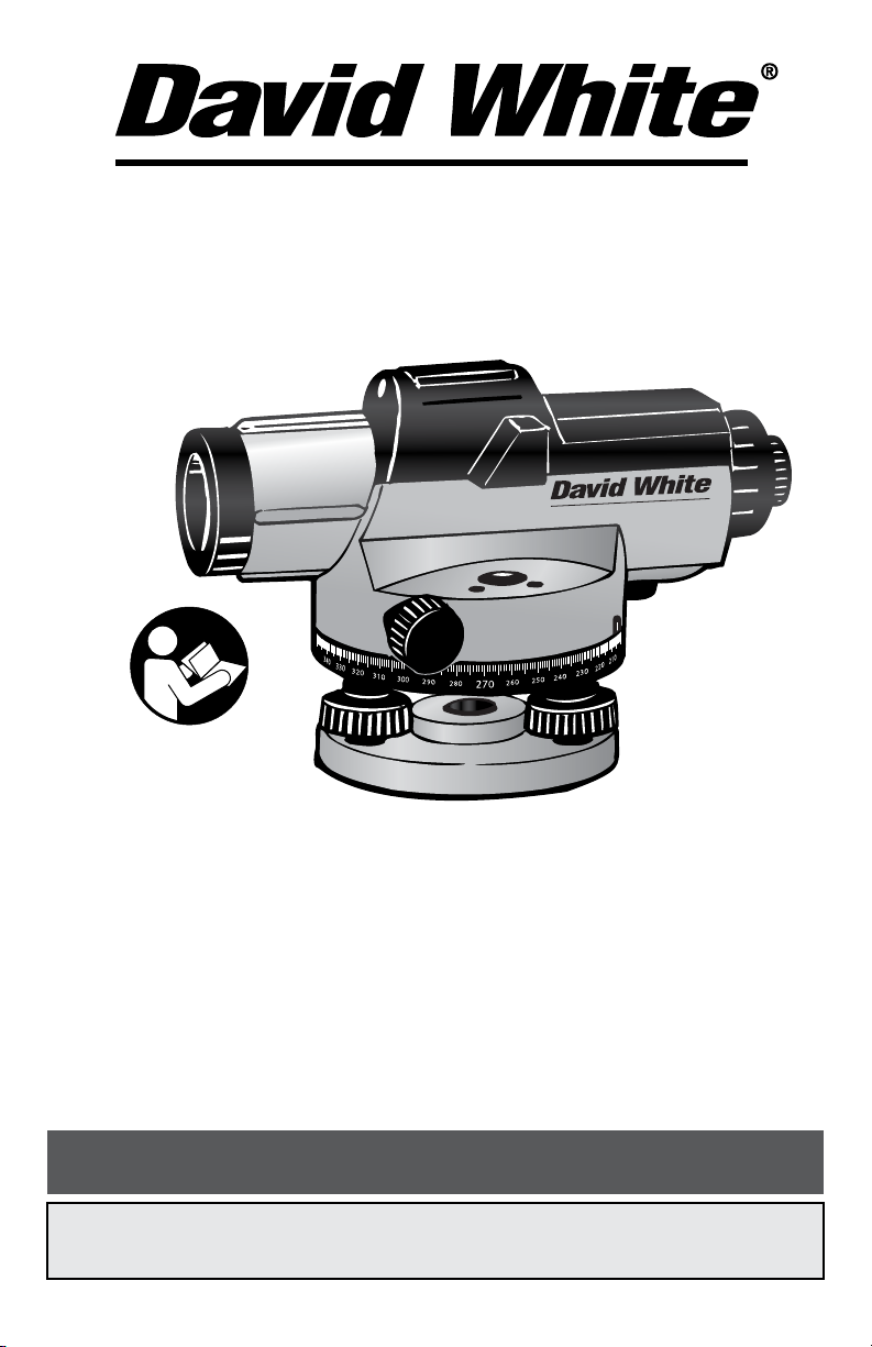
Measuring Angles
Centre the measuring tool above the
point from which on the angle is to be
measured.
BA
100’
(30 m)
a1b
d
1
BA
3’
(1 m)
a2b2
d
350
340
0
10
50 40
30
a2– d = b2
a1– b1= d
Direct the measuring tool against point A.
BA
100’
(30 m)
a1b
d
1
BA
3’
(1 m)
a2b2
d
350
340
0
10
50 40
30
a2– d = b2
a1– b1= d
Rotate the horizontal circle 11 with the
zero point toward the reference mark 10.
BA
100’
(30 m)
a1b
d
1
BA
3’
(1 m)
a2b2
d
350
340
0
10
50 40
30
a2– d = b2
a1– b1= d
Then direct the measuring tool against
point B. Read off the angle at the
reference mark 10. Angle measured in the
above example: 45°.
Accuracy Check of the
Instrument
Check the levelling and indication
accuracy of the measuring tool each time
before using and after longer transport of
the measuring tool.
Checking the Circular Bubble Vial
Align the measuring tool with the levelling
screws 13 so that the air bubble is
positioned in the centre of the circular
bubble vial 8.
Rotate the telescope by 180°. When the
air bubble is no longer in the centre of the
circular bubble vial 8, the circular bubble
vial must be readjusted.
Readjusting the Circular Bubble Vial
Bring the air bubble of the circular bubble
vial 8in a position between the centre and
the end position of the check by turning
the levelling screws 13.
BA
100’
(30 m)
a1b
d
1
BA
3’
(1 m)
a2b2
d
350
340
0
10
50 40
30
a2– d = b2
a1– b1= d
Using the Allen key 17, turn the adjusting
screws 12 until the air bubble is positioned
in the centre of the circular bubble vial.
BA
100’
(30 m)
a1b
d
1
BA
3’
(1 m)
a2b2
d
350
340
0
10
50 40
30
a2– d = b2
a1– b1= d
Check the circular bubble vial by rotating
the telescope by 180°. If required, repeat
the procedure or refer to an authorized
SitePro after-sales service.
Checking the Compensator
After aligning and focussing the
measuring tool, measure the height at
a reference point. Then press the lock
button of the compensator 9and release
again. Measure the height again at the
reference point.
If both heights do not exactly match,
have the measuring tool repaired by an
authorized SitePro after-sales service.
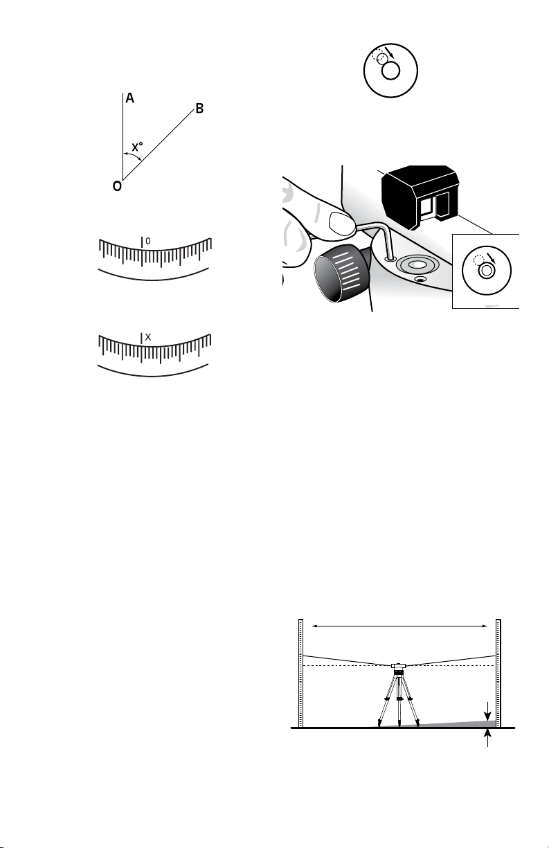
Checking the Crosshair
A measuring distance of approx. 100 ft
(30 m) is required for the check.
BA
100’
(30 m)
a1b
d
1
BA
3’
(1 m)
a2b2
d
350
340
0
10
50 40
30
a2– d = b2
a1– b1= d
Set up the measuring tool in the centre
and levelling rods Aand Bat both ends of
the measuring distance.
-9-
After aligning and focusing the measuring
tool, read the heights at both levelling
rods. Calculate the difference d between
the height a1of levelling rod Aand the
height b1of levelling rod B.
Example:
a1= 1.937m
b1= 1.689m
a1– b1= 1.937m– 1.689m = 0.248m=d
BA
100’
(30 m)
a1b
d
1
BA
3’
(1 m)
a2b2
d
350
340
0
10
50 40
30
a2– d = b2
a1– b1= d
Set up the measuring tool approx. 6 ft (2
m) away from levelling rod A. After aligning
and focussing the measuring tool, read
the height a2at levelling rod A.
Subtract the previously calculated value
d from the measured height a2in order to
receive the set value for the height b2at
levelling rod B.
Measure height b2at levelling rod B.
When the measured value deviates by
more than 3 mm (AL8-26) or 2 mm (AL8-
32) from the calculated set value, the
crosshair must be readjusted.
Example:
a2= 1.724m
d=0.248m
a2– d= 1.724 m – 0.248 m = 1.476m
AL8-26: When measuring, height b2must
be 1.476 m ±3 mm.
AL8-32: When measuring, height b2must
be 1.476 m ±2 mm.
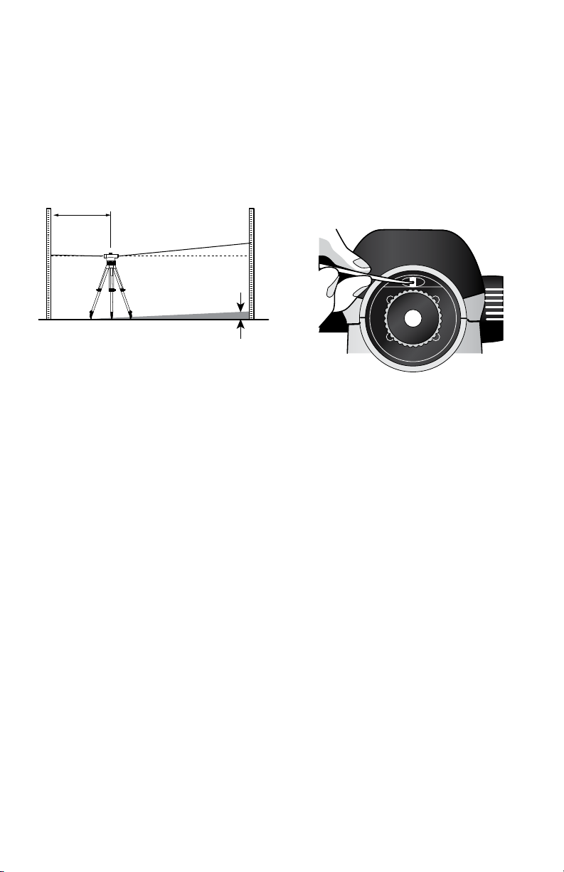
Readjusting the Crosshair
BA
100’
(30 m)
a1b
d
1
BA
3’
(1 m)
a2b2
d
350
340
0
10
50 40
30
a2– d = b2
a1– b1= d
Unscrew the eyepiece cover 5. Using
the adjusting pin 18, turn adjusting
screw 5 clockwise or anticlockwise,
until the calculated set value for height
b2is reached when measuring on
levelling rod B.
Screw on eyepiece cover 5again.

-10-
Store and transport the tool only in the
supplied protective case.
Keep the tool clean at all times.
Do not immerse the tool into water or
other fluids.
Wipe off debris using a moist and soft
cloth. Do not use any cleaning agents or
solvents.
Regularly clean the surfaces at the exit
opening of the laser in particular, and pay
attention to any fluff of fibers.
If the tool should fail despite the care
taken in manufacturing and testing
procedures, repair should be carried out
by an authorized after-sales service center
for Dave White’s SitePro instruments.
In all correspondence and spare parts
orders, please always include the
model number and serial number of the
instruments.
All precision instruments should be
cleaned, lubricated, checked and adjusted
ONLY at a qualified instrument repair
station or by the manufacturer, at least
once a year.
In case of repairs, send in the instrument
packed in its protective case.
ENVIRONMENT PROTECTION
Recycle raw materials
& batteries instead of
disposing of waste. The
unit, accessories, packaging
& used batteries should be sorted for
environmentally friendly recycling in
accordance with the latest regulations.
MAINTENANCE AND SERVICE

-11-
LIMITED WARRANTY
Dave White’s SitePro (“Seller”) warrants to the original purchaser only, that all David
White laser tools and optical instruments will be free from defects in material or
workmanship for a period of two (2) years from date of purchase.
SELLER’S SOLE OBLIGATION AND YOUR EXCLUSIVE REMEDY under this Limited
Warranty and, to the extent permitted by law, any warranty or condition implied by
law, shall be the repair or replacement of parts, without charge, which are defective
in material or workmanship and which have not been misused, carelessly handled,
or misrepaired by persons other than Seller or Authorized Service Center. To make
a claim under this Limited Warranty, you must return the complete laser, optical
instrument or David Whte product, transportation prepaid, to SITEPRO Service
Department or Authorized Service Center. Please include a dated proof of purchase
with your tool. For locations of nearby service centers, please call 1-855-354-9881.
THIS LIMITED WARRANTY DOES NOT APPLY TO ACCESSORY ITEMS SUCH
AS TRIPODS, RODS, HAND LEVELS, FIELD SUPPLIES, TAPES, MOUNTING
DEVICES AND OTHER RELATED ITEMS. THESE ITEMS RECEIVE A 90 DAY LIMITED
WARRANTY.
To make a claim under this Limited Warranty, you must return the complete product,
transportation prepaid. For details to make a claim under this Limited Warranty please
visit www.davidwhite.com or call 1-855-354-9881.
ANY IMPLIED WARRANTIES SHALL BE LIMITED IN DURATION TO ONE YEAR
FROM DATE OF PURCHASE. SOME STATES IN THE U.S., AND SOME CANADIAN
PROVINCES DO NOT ALLOW LIMITATIONS ON HOW LONG AN IMPLIED
WARRANTY LASTS, SO THE ABOVE LIMITATION MAY NOT APPLY TO YOU.
IN NO EVENT SHALL SELLER BE LIABLE FOR ANY INCIDENTAL OR
CONSEQUENTIAL DAMAGES (INCLUDING BUT NOT LIMITED TO LIABILITY FOR
LOSS OF PROFITS) ARISING FROM THE SALE OR USE OF THIS PRODUCT. SOME
STATES IN THE U.S., AND SOME CANADIAN PROVINCES DO NOT ALLOW THE
EXCLUSION OR LIMITATION OF INCIDENTAL OR CONSEQUENTIAL DAMAGES, SO
THE ABOVE LIMITATION MAY NOT APPLY TO YOU.
THIS LIMITED WARRANTY GIVES YOU SPECIFIC LEGAL RIGHTS, AND YOU MAY
ALSO HAVE OTHER RIGHTS WHICH VARY FROM STATE TO STATE IN THE U.S.,
OR PROVINCE TO PROVINCE IN CANADA AND FROM COUNTRY TO COUNTRY.
THIS LIMITED WARRANTY APPLIES ONLY TO PRODUCTS SOLD WITHIN THE
UNITED STATES OF AMERICA, CANADA AND THE COMMONWEALTH OF PUERTO
RICO. FOR WARRANTY COVERAGE WITHIN OTHER COUNTRIES, CONTACT
YOUR LOCAL BOSCH DEALER OR IMPORTER.
David White is a registered trademark and distributed exclusively by SitePro.

42345D8932 09/15 Printed in China
© Dave White’s SitePro 7619 S 1150 E Otterbein, IN 47970
Tel. +1 (765) 581 4097
This manual suits for next models
1
Table of contents
Popular Tools manuals by other brands

Kompernass
Kompernass KH 3210 operating instructions

Tyco Electronics
Tyco Electronics 411-15684 instruction sheet

Fortum Proffesional
Fortum Proffesional 4759999 Translation of the original user manual

Imperial
Imperial 700-F Operation and service instructions

Desoutter
Desoutter PT Series Servicing and operating instructions

Rockler
Rockler 53651 instructions


