KENT Nordco KF3BM User manual

K
KF
F3
3B
BM
M
N
No
or
rd
dc
co
o
H
Hy
yd
dr
ra
au
ul
li
ic
c
H
Ha
am
mm
me
er
r
O
Ow
wn
ne
er
r’
’s
s
M
Ma
an
nu
ua
al
l
This manual applies to Kent Hammer S/N 5001 & Above
• The policy of Kent Demolition Tools is one of continual improvement. We reserve the right to change
design, materials, or specifications at any time, without notice or creating any obligation to previous or
future customers.
• The information contained in this manual is provided at no charge to the customers of the Kent Demolition
Tool Company, a Division of Gougler Industries, inc., Kent, Ohio.
• We hereby grant to our customers the right to reproduce individual pages, electronically or by photocopy,
when used in support of the Kent product described herein, provided that no changes are made to the
material information, no reproductions are sold, and no part of this manual is incorporated in any
publication without the specific written permission from the Kent Demolition Tool Company.
Last Revision: November 2005


NOV/2005 Preface – Page #1
KENT'S COMMITMENT TO ITS CUSTOMERS
For over 45 years, Kent has been dedicated to designing and manufacturing a broad
line of top-performing, quality tools for the demolition and construction industries. We are
continuously gathering experience from many work areas and using that experience to
manufacture the best tools available to meet the needs of ever-changing market
requirements.
Kent demolition tools have been designed from the inside out to deliver the rugged and
dependable day-in and day-out performance you need to get the job done, to minimize
downtime, and to keep the job moving on budget and on schedule. With our wide choice of
hydraulic hammers, pneumatic hammers, concrete crushers, pedestal units,
compactor/drivers, hand-held tools and accessories, you can always choose the right
combination for maximum job productivity.
Kent supports you every step of the way with things like on-site engineering for custom
design work, two strategically located warehouse facilities with extensive tool inventories
assuring on-time deliveries, experienced parts personnel who know how to listen, and a
nationwide distribution network for fast-access sales and service. These are just a few of
the reasons to rely on Kent to satisfy all of your demolition requirements.
Sincerely,
Kent Demolition Tool Co.

Preface – Page #2 NOV/2005
TABLE OF CONTENTS
SECTION A GENERAL INFORMATION
2 HAMMER SPECIFICATIONS
3 SAFETY PRECAUTIONS
4 HAMMER CONSTRUCTION
5 PRINCIPLE OF OPERATION
SECTION B MAINTENANCE
2 LUBRICATION
4 ACCUMULATOR DISASSEMBLY PROCEDURE
8 ACCUMULATOR RE-ASSEMBLY PROCEDURE
10 ACCUMULATOR CHARGING PROCEDURE
14 TORQUE REQUIREMENTS
SECTION C TROUBLESHOOTING
SECTION D PARTS LIST
2 KF3BM HAMMER PARTS
4 KITS:
4 HAMMER LIFTING EYE KIT
5 HAMMER CHARGE KIT
6 ACCUMULATOR KIT
7 SEAL KIT

NOV/2005 Section A – Page #1
SECTION A
GENERAL INFORMATION

Section A – Page #2 NOV/2005
KF3BM
350# Class Hammer
SPECIFICATIONS:
Mounting Style . . . . . . . . . . . . . . . Bare Hammer Power Unit
Weight . . . . . . . . . . . . . . . . . . . . . 162 lbs. (74 Kg)
Length . . . . . . . . . . . . . . . . . . . . . 33.3 in. (845 mm)
AEM Impact Energy Rating . . . . . . 162.0 ft./lbs. (219.6 joules)
AEM Test Flow Rate . . . . . . . . . . . 8.96 GPM (33.92 L/min)
AEM Test Frequency . . . . . . . . . . . 1158.60 BPM (19.31 Hz)
AEM Supply Line Pressure . . . . 1976.86 PSI (136.30 Bar)
Blows/Minute . . . . . . . . . . . . . . . 700 ~ 900
Acceptable Oil Flow. . . . . . . . . . . . 6.5 ~ 10.5 G.P.M.
Operating Pressure . . . . . . . . . . . . 1450 ~ 2500 P.S.I.
Chuck Diameter . . . . . . . . . 2 in. (52 mm)

NOV/2005 Section A – Page #3
SAFETY PRECAUTIONS
Before installation or operation of the hydraulic hammer, the operator and maintenance
personnel should read and understand the following safety precautions:
•The safety alert symbol
!
means ATTENTION! Your safety is involved!!
•No bystanders are allowed in the vicinity of the hammer while it is in use.
•Stay clear of the hammer while it is in operation. Flying objects can cause severe injuries, or
even death.
•Always wear safety glasses and ear protection when operating the hammer.
•Always wear safety glasses during installation, service or any activities associated with the
hammer.
•Operate the hammer only when the operator is seated with full control of the machine.
•Use the hammer for its intended purpose only.
•When installing or removing the hammer, keep hands and fingers clear of the mounting pin
holes and linkage.
•Make frequent inspections of the hammer and base machine as described in the "Daily
Inspection" section of this manual.
•Do not make any alterations to the hammer without the authorization of Kent's Product Support
Department.
•Anytime service is performed on the hammer, hydraulic pressure in the line must first be
released. Then disconnect the hydraulic lines themselves.
•Never disassemble the hammer without first releasing the gas charges. Failure to comply can
result in serious injuries or death.
•Use only Kent/Nordco replacement parts.
•Never use hands to search for hydraulic fluid leaks, use a piece of paper or cardboard.
Escaping fluid under pressure can be invisible and can penetrate the skin and cause a
serious injury. If any fluid is injected into your skin, see a doctor immediately. Injected
fluid MUST be surgically removed by a doctor familiar with this type of injury or
gangrene may result.

Section A – Page #4 NOV/2005
GENERAL CONSTRUCTION OF THE
HAMMER
1. ACCUMULATOR
The accumulator stores hydraulic fluid for use
during the hammering cycle. It also absorbs any
pulsations seen by the hydraulic circuit.
2. BACKHEAD
The hydraulic ports (pressure and return) are
built into the backhead.
3. THROUGH BOLTS
The three (3) major parts of the hammer, the
front head, cylinder and the backhead, are secured by
four (4) through bolts
4. VALVE
The valve fits over the piston inside the
cylinder, and controls the piston reciprocation.
5. PISTON
The kinetic energy of the piston during the
operation of the hammer, is converted into impact
energy when it is transmitted to the working steel.
6. CYLINDER
The hydraulic circuit for reciprocating the
piston is built into the cylinder. The cylinder is the
heart of the hammer.
7. FRONTHEAD
The fronthead supports the entire hammer.
Due to the shock transmitted by the working steel, the
thrust ring and thrust bushing are built-in.
8. ANVIL
The anvil transmits the piston’s impact energy
onto the spike head.

NOV/2005 Section A – Page #5
PRINCIPLE OF OPERATION
The impact energy is a product of the force acting on piston and the length of its stroke. The
piston is powered by the direct action of the hydraulic oil pressure and flow to the hammer.
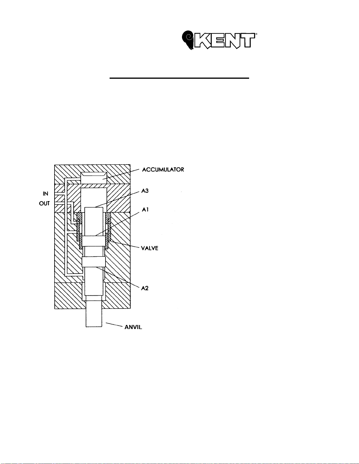
The following illustration is a simplified sketch of the hydraulic oil porting of the hammer. Area
(A1) of the piston is larger than area (A2) of the piston. Area (A1) is alternately connected to the
pressure (IN) or the return (OUT) lines of the hammer by the valve. Area (A2) is always connected
to the pressure (IN) line. Area (A3) is an unpressurized chamber which allows for the free
movement of the piston.
The piston rises when area (A1) is
connected to the return (OUT) line. The oil
pressure on area (A2) is greater than the
oil pressure acting on area [A1], driving the
piston upward.
At the end of the return stroke, the
valve shifts, diverting the oil to area (A1) of
the piston. The oil pressure drives the
piston downward striking the working steel.
The kinetic energy of the piston at this
point is transferred to the working steel.
The working steel is then driven into the
material to be broken. At this point, the
valve shifts back to its original position,
causing the cycle to repeat.
To maintain continuous oil flow during
the valve shift, a bladder-type accumulator
is utilized. The accumulator acts as a
variable size reservoir for the oil, allowing
for continuous oil flow during the time the
piston is changing direction. This reduces
the pulsations in the hydraulic system.

Section A – Page #6 NOV/2005
This page intentionally blank

NOV/2005 Section B – Page #1
SECTION B
MAINTENANCE

Section B – Page #2 NOV/2005
LUBRICATION
Kent's KF3BM hydraulic hammer is equipped with one (1) grease fitting. This fitting is
located on the front bushing, near the anvil (refer to the illustration below). Lack of
lubrication can cause failure of the anvil, piston or shorten the life of the seals. An NLGI
NO.2 grease is recommended.
• The fronthead should be
lubricated daily. Grease more
frequently, if needed, but do not
over-load the tool with grease.
• Make certain the anvil is fully
engaged prior to greasing.

NOV/2005 Section B – Page #3
Accumulator Disassembly/Assembly:
Before you attempt to disassemble the accumulator, you should become familiar with the
components of the accumulator. They are as follows:
General Note: When disassembling the accumulator, inspect all parts for wear and replace
as necessary before reassembly.
Tools required for this procedure:
Adjustable or 22mm wrench
5mm Hex key (allen wrench)
14mm Hex key (allen wrench)
4# hammer
vise
600 or finer grit paper
Anti-Seizing Agent (for reassembly)
Spanner wrench (for accumulator disassembly and reassembly)

Section B – Page #4 NOV/2005
Disassembly Procedures:
Discharge the Nitrogen:
ACCUMULATOR IS UNDER HIGH PRESSURE! DO NOT STAND OVER THE
CHARGE PORT LOCATED ON TOP OF THE ACCUMULATOR. FAILURE TO
DO SO MAY RESULT IN BODILY INJURY.
1. Remove accumulator plug (on top of
accumulator) and valve cap (on side of
accumulator) using 22mm or adjustable
wrench.
2. Using a 5mm allen wrench, slowly
unscrew the needle valve a few turns at
a time. Wait a few seconds after each
series of turns. This will discharge gas
from the accumulator. DO NOT
REMOVE VALVE AT THIS TIME!
NOTE: If foam begins to exit the hole
in the top of the accumulator cover this
signals that the diaphragm has been
ripped and hydraulic oil has entered the
top of the accumulator.
After the nitrogen gas has been thoroughly bled from the system, continue
unscrewing the needle valve. Set aside for inspection and cleaning.

NOV/2005 Section B – Page #5
Disassembly Procedures (Continued):
3. Using a 14mm allen wrench, remove the accumulator by removing the set
screws holding the accumulator to the back head. (Note: If you have the
optional lifting eye kit installed this must be removed as well.)
4. Turn the accumulator upside
down and insert it into a vise.
Lock it securely. Do NOT use
the large nut in the center of the
accumulator body to loosen the
body. Step 5 will instruct you on
how to properly remove the body
from the cover.
Removal of the nut will cause damage to the accumulator and cause it to
malfunction. In the even that you have tried to turn the nut:
• Continue to rotate the nut until – when you look into the rings of the
accumulator body – the diffuser rings are fully open and there are no
webs blocking the holes.
• Tackweld the nut to the accumulator body.

Section B – Page #6 NOV/2005
Disassembly Procedures (Continued):
5. Using a spanner wrench (Nordco
P/N 4011560), insert the 4 pins
on the wrench into the matching
holes at the bottom of the
accumulator. This may require
tapping the wrench pins – with
the hammer butt - into their
corresponding holes.
6. Gently tap a 4# hammer on the
wrench handle, moving it in a
counterclockwise (CCW)
direction. This is done only until
the accumulator body has been
loosened to the point you can
turn it by hand. At this point
remove the spanner wrench by
gently tapping up with the
hammer butt. Be careful not to
use too much force to remove
wrench. This may strip the
threads on the accumulator body.
7. Remove the body and
diaphragm. Dispose of the
diaphragm.

NOV/2005 Section B – Page #7
Disassembly Procedures (Continued):
8. Wash the accumulator body and cover in solvent.
9. Inspect the inside of the accumulator cover and body for burrs or nicks. If burrs
are found, they can be removed by using 600 grit or finer paper. If nicks are
found, replace the part.
If nicks or burrs are left inside the accumulator, damage to the diaphragm will
occur during charging procedures.
10. Clean the face of the accumulator. (where it mates to the back head of the
hammer).

Section B – Page #8 NOV/2005
Re-Assembly Procedures:
Apply a coat of anti-seize agent to prevent
scores to threaded pant of accumulator body.
Place the new diaphragm carefully to seat in the
outer circumferential groove. Lubricate the round
notches of the outer circumferential face of the
diaphragm with high-quality grease.
Lubricate the thread of the outer circumferential
part of the accumulator body with anti-seize
lubricant.
Set the accumulator cover.
Clean the inside of the washed accumulator cover
with a fresh cloth. Put the accumulator cover onto
the accumulator body, and fasten it by turning it by
hand.
★ Notice:
Be careful not to damage the thread during
assembly.
Inspect o-rings on the plug and the valve cap.
Replace as required. Reassemble to
accumulator cover as shown. Torque valve
cap and plug to 110 ft./lbs.

NOV/2005 Section B – Page #9
Re-Assembly Procedures:
Charging of nitrogen gas
After the accumulator has been reassembled,
loosen the vise, and set it back again with the
outside up.
The accumulator can be charged with Nitrogen
gas at this time (following the procedures on
page 10) or can be mounted back on the
hammer and charged later.
When mounting accumulator to back head, torque
cover bolts to 180 ft./lbs.

Section B – Page #10 NOV/2005
ACCUMULATOR CHARGING PROCEDURE
To receive the optimum performance from the hydraulic hammer, care must be taken to maintain
the proper nitrogen charge in the accumulator of the hammer. To assist with this, a charge kit is
available. Refer to Section D, Page 5.
NOTE: The customer supplied nitrogen tank MUST be equipped with a regulator!
The following is a step-by-step procedure that should be used to properly charge the accumulator.
These are written for use with the charge kit. The accumulator can be safely charged either on or
off the hammer, as long as these procedures are followed:
STEP ILLUSTRATION
STEP 1
If you haven’t already done so,
assemble all items of the Charge
Kit with the exception of Items 3
and 4. Note: The charge kit, with
the exception of items 3 and 4, is
to be stored as a complete unit
and does not require
disassembly.
Make certain that the shut-off
valve (12) is fully closed
(clockwise).
STEP 2
Remove the plug and o-ring from
the top of the accumulator cover
using a 22mm or adjustable
wrench. Replace with Charge Kit
Adapter (#3) and O-ring (#4).
Table of contents
Other KENT Tools manuals