Imperial 700-F Operation manual

No. 700-F TUBE BENDER
Operation and Service Instructions
With Replacement Parts List
Warning!
Keep body parts away from pinch/bend areas while using.
Ensure tubing is secure in tool before bending.
Always wear approved eye protection.
Broken materials may fly.

11
12
13
14
15
16
17
18
19
20
Part Name
74588
74589
74554
74555
74569
74572
74575
74578
74581
74584
BLOCK (3/8 & 1/2”)
BLOCK (5/8 & 3/4”)
SHAFT (1/4”)
SHAFT (5/16 - 3/4”)
BLOCK GEAR ASSEMBLY (1/4”)
BLOCK GEAR ASSEMBLY (5/16”)
BLOCK GEAR ASSEMBLY (3/8”)
BLOCK GEAR ASSEMBLY (1/2”)
BLOCK GEAR ASSEMBLY (5/8”)
BLOCK GEAR ASSEMBLY (3/4”)
1
2
3
4
5
6
7
8
9
10
74603
74608
74609
74591
74565
74566
74567
74568
74587
CARRYING CASE ASSEMBLY
BASIC TUBE BENDER ASSEMBLY
RATCHET WRENCH
WRENCH
YOKE ASSEMBLY
RACK
FORM SHOE (1/4 & 5/16”)
FORM SHOE (3/8 & 1/2”)
FORM SHOE (5/8 & 3/4”)
BLOCK (1/4 & 5/16”)
Index
No.
Imperial
Part No. Part Name
Index
No.
Imperial
Part No.
12 11 10
13 14
987
18
15 16
19 20
17
5
4
2
6
3
1
Printed in U.S.A.
2
Fig. 1 Main Components

SECTION I
USE AND MAINTENANCE
1. INTRODUCTION
6. DESCRIPTION AND FUNCTION
NOTE
TABLE 1. TUBE SIZES
Tube diameter
(O.D. inches)
Wall thickness
(inches) Bend radii, measured to center-line of tubing
9/16
11/16
15/16
1 -1/4
1 -1/2
1 -3/4
0.016 - 0.049
0.020 - 0.065
0.028 - 0.083
0.035 - 0.083
0.042 - 0.083
0.049 - 0.083
1/4
5/16
3/8
1/2
5/8
3/4
8. Before bending is started, the tube is clamped into
the machine between the form block and form shoe and
positioned at the normal starting point which is
indicated by a dial on the tube bender proper. By
watching the dial, any desired degree of bend can be
effected, since the dial indicates accurately all
movements of the form block and shoe. To properly hold
the tube at the beginning point of the bend a clamp
yoke, which must be fitted with the proper size clamp
block, is provided. The clamp block has the correct
radius to match the radius of the form block which has
been selected for the particular diameter of the tube to
be bent.
9. The tube bender proper is operated with the ratchet
handle included. A large pad on the underside of the
housing is provided for clamping between the jaws of a
vise which must be 4 inches or larger in order to hold
the machine safely. All accessories for use with the tube
bending machine proper are quickly installed and
removed, making the selection of sizes and actual
bending a fast and practical operation.
10. The tube bending machine is not intended for
permanent installation. Each part of the complete kit
has a special place in the carrying case, thus making
the equipment completely portable so that it can be
transported from one location to another.
2.This handbook provides descriptive data, installation,
operation and maintenance, and replacement parts list
for the Imperial 700-F Tube Bender Kit.
3. Information contained in Section 1 is presented for
the purpose of providing personnel, responsible for
using and servicing the tube bender, with factory
approved data to ensure successful results in the use
and repair of the equipment. Section II lists and
illustrates replaceable assemblies and subassemblies,
and individual parts that can be procured when
replacements are required.
4. Each tube bender kit is packaged in a strong steel
carrying case which is equipped with brackets and
studs placed to hold individual components in an
orderly arrangement. The equipment contained in the
kit is designed to bend cold drawn, corrosion resistant
steel tubing conforming to Specification MIL-T-6845,
with outside diameters and wall thickness specified in
Table 1.
7. The Tube Bender Kit will bend corrosion resistant,
cold drawn steel tubing, conforming to Specification
MIL-T-6845, in sizes and wall thickness listed in Table 1.
When operating according to instructions contained
herein, bends up to 180° can be made while retaining
the original diameter of the tube within 5% at the bend.
Bends are not restricted to a single plane. A wide range
of compound bends and “S” bends can be handled.
5. Each form block assembly has a gear sector pinned
directly to it, however, a single rack is used with all sizes
of form shoes.The drive shaft having upper splines of
the larger diameter handles form blocks from 5/16
inch to 3/4 inch inclusive, while the drive shaft with the
smaller diameter upper splines handles only the 1/4
inch form blocks.
Although the tube bender is designed specifically for
bending stainless steel tubing, aluminum, copper
and tubing of various alloys can be handled
successfully provided the combined hardness and
elongation characteristics are within the range of
Specification MIL-T-6845. In some cases the wall
thickness listed in Table 1 can be exceeded when
bending aluminum and copper. Experience in using
the machine will best determine what ranges can be
handled successfully with tubing other than stainless
steel.
3

Figure 2. Clamping the Tube Bender Proper in a Vise
11. OPERATION.
12. SETTING UP THE MACHINE. (See Figure 2.)
a. Use a substantial vise with strong, firm-gripping jaws.
Open the jaws wide enough to receive the boss on the
underside of the housing and clamp the tube bender
proper securely between the vise jaws, making certain the
jaws are tight enough to prevent any possibility of the
machine slipping out during actual bending operations.
Considerable force is required on the ratchet handle for
bending 3/4 inch stainless steel tubing, having maximum
wall thickness, and a weak-jawed vise would not hold the
machine.
b. Select the proper size drive shaft to fit the form block
of the required size and insert the drive shaft into the tube
bender proper with the large splines downward. (See
figure 3.) Make certain the drive shaft splines are fully
engaged and that the drive shaft is inserted all the way
into the tube bender so that the lower journal is in the
inner race of the ball bearing.(43, figure 12.)
Figure 3. Installing Drive Shaft in Tube Bender Proper
c. Select the proper size form block and install it on the
drive shaft. (See figure 4.) Rotate the squared countershaft
drive end (37, figure 12) by hand to position the form
block with the starting point of the groove parallel with the
form shoe, when installed.
Figure 4. Placing the Form Block on the
Drive Shaft Spline
NOTE
If the feed screw is turned in too far, the form
shoe slide block will interfere with installation of
the form block.
d. Select the proper size clamp block, turn it so that the
correct groove will be facing outward and slide the clamp
block into the clamp yoke. (See figure 5.)
Figure 5. Installing Clamp Block in Clamp Yoke
e. Place the tube to be bent in the groove of the form
block, at the location of the desired bend, and clamp it
into place with the clamp yoke. (See figure 6.) Make sure
the clamp yoke is in proper position
DRIVE SHAFT
FORM BLOCK
FEED SCREW
DRIVE SHAFT
CLAMP BLOCK
CLAMP YOKE
4

Figure 7. Attaching the Rack to the Form Shoe
NOTE
g. While holding the rack in engagement with the form
shoe, slide the form shoe into place alongside the tube
which is clamped into the form block. The end of the form
shoe should be inserted far enough to almost touch the
clamp yoke. (See figure 8.) If the form shoe slide block is
in too far to permit insertion of the form shoe, retract the
feed screw until the form shoe can be slipped into place.
h. While holding the form shoe against the tube to be
bent, rotate the feed screw until the pressure plate in the
form shoe slide block is in light contact with the form shoe.
(See figure 9.) This will hold the form shoe in place while
making further preparations for making the bend.
Do not tighten the feed screw at this time, as it will
spring the screw post enough to prevent engagement
of the tension yoke.
i. Rotate the bend indicating plate (dial) until the slot at
the center of the dial is parallel with the flat key milled on
the upper end of the drive shaft. Move the tension yoke
into position and press downward until the milled key on
the end of the drive shaft passes through the cap slot at the
center of the dial. (See figure 10.)
Figure 8. Sliding the Form Shoe and Rack
Into Position
Figure 9. Rotating Feed Screw With
Double Ended Wrench
NOTE
If difficulty is experienced in engaging the
tension yoke, loosen the feed screw slightly.
j. For original bends in straight tubing, the parts should
be positioned so that the dial is set at zero, however, the
initial starting point can be positioned at any desired
location to accommodate tubes already having partial
bends. When the dial is engaged with the milled key on
the end of the drive shaft the degree of the bend already
in the tube will be indicated.
5
Figure 6. Tightening the Clamp Yoke on the
Form Block
on the form block. Tighten the clamp yoke screw with the
double-ended wrench provided.
f. Select a form shoe containing the correct size groove for
the tube to be bent, and engage the dowels on the rack into
the holes on the underside of the form shoe. (See figure 7.)
The form shoe can be turned end to end, with respect to the
rack, to select the proper size groove in the form shoe.
WRENCH
CLAMP YOKE
FORM SHOE TUBE
WRENCH
FEED SCREW
TUBE
FORM SHOE
RACK

Figure 11. Forming a Bend with Tube Bender
Clamped in a Vise
b. While the ratchet handle is being operated, the form
block rolling against the form shoe will bend the tube to the
same radius as the groove in the form block. Before begin-
ning the bend, determine the angle of bend desired and
operate the ratchet handle until the dial indicates the pre-
determined degree of bend. When the tubing is released
from the tube bender, Ordinary cup grease and similar lubricant
there will be a small amount of "spring-back"; the actual
amount varying in proportion to the hardness and
elongation characteristics of the tubing. This "spring-back"
will also increase the diameter of the bend slightly.
Experience will best determine the exact amount of
"spring-back" and dictate the amount of over-run required
in order to anticipate the exact degree of bend acquired
after the tubing is released.
NOTE
Lubricants are neither required nor recommended
on any of the parts during bending operations.
c. When bending is complete, remove the ratchet handle,
loosen the feed screw and lift the tension yoke straight up
until free of the drive shaft. Rotate the tension yoke to one
side and remove the form shoe from the tube bender.
Release the tube from the form block by loosening the screw
in the clamp yoke.
NOTE
After finishing with the equipment, pack all parts
in the carrying case to prevent misplacement of
components.
14. MAINTENANCE.
15. The tube bender and accessories are calculated for
stresses well in excess of any stress that will be encountered
in actual tube bending operations. As a result, very little
maintenance should be required at any time, provided the
external components are kept free of dust and grit which
would produce excessive wear on the parts.
16. CLEANING.
17. Dust, dirt and other foreign material should not be
permitted to collect on the feed screw, pressure plate, form
shoe, slide block and other exposed parts of the machine.
Foreign material should also be wiped off form blocks, form
shoes, rack and sector gears before beginning any bending
operation. Remove foreign material with a stream of
compressed air, aided by a soft bristle brush if particles are
difficult to dislodge. Wipe all parts including the housing
occasionally with a clean cloth. If grease and other
stubborn accumulations are present on the parts, wet the
cloth with naphtha or dry cleaning solvent, Federal
Specification P-S-661b.
18. LUBRICATION.
19. All bearings, gears and parts located inside the housing
are lubricated during assembly by packing gear teeth with
extreme-pressure, low-temperature grease, Specification
MIL-G-7118, or equivalent. No lubrication is required
except when the tube bender proper is disassembled for
repairs, at which time the old grease should be removed by
washing in dry cleaning solvent, Federal Specification P-S-
661b, and repacking with fresh grease of the above specifi-
cation, or equivalent.
6
CAUTION
Figure 10. Engaging the Tension Yoke and Dial
13. BENDING PROCEDURE.
k. After engaging the dial, tighten the feed screw securely
to force the faces on the form shoe against the faces on the
form block. (See figure 9.)
Make sure the teeth on the rack are meshed with
the teeth on the sector gear before tightening the
feed screw.
a. Engage the ratchet handle with the square end of the
shaft which protrudes from the side of the housing. Rotate
the shaft in a clockwise direction. (See figure 11.)
CAUTION
DIAL
TUBE
TENSION YOKE
TUBE
FEED SCREW
RATCHET
HANDLE

must not be used, since they will not withstand the extreme
contact pressures. If grease of the above specification, or an
equivalent, is not available, be sure to use an
extreme-pressure, low-temperature grease from a reliable
commercial source.
20. TROUBLE SHOOTING.
21. Principal troubles that might be encountered, together
with their possible causes and remedies, are given in
Table II.
Trouble
TABLE II. TROUBLE SHOOTING
RemedyProbable Cause
TUBE WRINKLES ON INNER
RADIUS OF BEND
RIDGES ARE FORMED ON
TUBE AT BEND
TUBING MARRED AT BEND
DRIVE SHAFT FAILS TO RO-
TATE WHEN RATCHET IS
OPERATED
TUBE BENDER BINDS OR
LOCKS
Tubing 0. D. is undersize or out
of tolerance specified in Table I,
and therefore does not properly
fit the grooves in the form block
and shoe.
Feed screw not tightened suffi-
ciently to force edges of form
block and shoe together.
Incorrect size of form block and
shoe being used
Damaged form block and/or shoe
Shear pin sheared in drive end
permitting it to slip on shaft
Damaged gears
Worn gears
Damaged ball bearings
Use proper size tubing.
Tighten feed screw.
Change to correct size of form
block and shoe.
Replace damaged components.
Install a new shear pin.
(38, figure 12. )
Disassemble the tube bender
proper and replace damaged
parts.
Disassemble the tube bender
proper and replace damaged
parts.
Replace ball bearings.
22. DISASSEMBLY. (See figure 12.)
NOTE
a. Remove the cap screw (21) and lock washer (22) to free
the screw post (20) from the upper half housing (28). Slide
the form shoe slide block (19) off the slide block support
(24). If removal of the feed screw (18) from the form shoe
slide block (19) is required, drive out the spring pins (17)
with a long point punch to release the feed screw (18).
If the tube bender proper is operating normally, it is
not necessary to disassemble it at regular calendar
overhaul periods. The only time overhaul
operations are required is when internal trouble is
suspected, at which time the two housing sections
should be separated, all parts cleaned and
inspected, damaged parts replaced and the
housing packed with fresh lubricant.
b. If the slide block support (24) is worn or damaged,
remove the two screws (25) to free the slide block support
(24) from the upper half housing (28).
c. Do not remove the name plate (26) unless it is broken,
or the data thereon is illegible. If removal is required,
remove the two drive screws (27).
d. Remove all socket head screws (29) and lock washers
(30) from the lower half housing (44). It may
be necessary to tap along the parting edges of the upper
and lower half housings (28 and 44) to separate them. Use
the sharp end of a screwdriver blade to pry the housings
apart, if necessary, while exercising care to avoid damaging
the mating surfaces of the two housing valves.
e. After the upper and lower half housings (28 and 44) are
separated, most assemblies can be lifted out of their
respective locations. It may be necessary to use a wood
dowel as a drift to tap the bearings out of their respective
recesses.
f. To remove the spacer (40), drive out the pin (38) with a
long point punch. Make certain the counter-shaft drive end (37)
is properly supported when driving out the (shear) pin (38).
g. Slide the worm gear (35) off the shaft (41).
h. Further disassembly will consist of separating individual
parts that normally would not require removal. The location
of each of these parts is shown in figure 12, and removal or
installation should be obvious since all parts are exploded
out from their proper locations.
23. INSPECTION.
24. The following table provides basic inspection
procedures for all parts of the tube bender assembly. These
checks are to be considered as basic, however, if other
damage not covered in the table is obvious such parts
should be replaced.
7

Inspection
INSPECTION OF INDIVIDUAL PARTS AND COMPONENTS
(See figure 12 for reference numbers)
Nomenclature
Ref. No.
2
3
4
7
8
10
11
12
13
14
15
18
19
20
23,39
and 43
24
26
28
31
32
Bend indicating plate cap
Sleeve bearing
Bend indicating plate (dial)
Form block assemblies
Clamp block
Clamp block pressure pad
Clamp yoke screw
Clamp yoke
Form shoe
Rack
Pressure plate
Feed screw
Form shoe slide block
Screw post
Ball bearings
Slide block support
Name plate
Upper half housing
Drive shaft
Drive gear
Replace if broken or if slotted hole at center is badly worn.
This would cause incorrect readings.
Check for fit on upper end of drive shaft (31). Replace bearing
if excessively loose, as this would cause undue strain on
certain parts.
Replace if bent or cracked.
Check for damage to form grooves, damaged or worn splines
at center and loose sector gear. Loose sector gears can be
tightened by installing new pins, but the blocks should be re-
placed for other conditions. Sector gears having worn or
damaged teeth should be replaced.
Replace if chipped or distorted.
Replace if bent.
Replace if threads are worn or damaged.
Replace if cracked or distorted. Also check for damaged
threads, and if retapping fails to restore threads, replace the
yoke.
Check for bends, twists and damaged forming channels. Re-
place for any of these conditions.
Check for bends, worn or damaged gear teeth and damaged
dowels. Replace for any of these conditions.
Replace if worn or cracked.
Replace if bent, or if threads are damaged.
Check for distortion and wear in track on underside of block.
Replace for either condition.
Check for bends and damaged or worn feed screw threads.
Replace for either condition.
Hold the outer race and rotate the inner race to determine if
bearings are rough or worn. Rotation should be smooth and
free of resistance except for slight pressure produced by the
bearing seals. If bearings are loose, rough, or if seals are
damaged the bearings should be replaced.
Replace if worn, cracked or bent.
Replace only if damaged, or if data on plate is not clearly
visible.
Check for cracks, stripped threads and distortion. Distortion
can be detected by placing the parting surface of the housing
against a surface plate. Contact should be made throughout
the entire parting surface.
Check for excessive wear on splines at both ends, and wear on
milled key at the top end. Replace for either condition.
Check for damaged or worn splines and rough or worn teeth.
Replace for either condition.
8

InspectionNomenclature
Ref. No.
INSPECTION OF INDIVIDUAL PARTS AND COMPONENTS (Cont)
33
35
36
37
38
40
41
42
44
All
All
Sleeve bearings
Worm
Key
Countershaft drive end
Pin
Spacer
Shaft
Ratchet handle
Lower half housing
Screws and nuts
Pins
Check for wear by trying the bearing on its respective shaft
journal. If more than 0. 002 inch clearance exists, replace
the bearing.
Check for cracks and worn thread. Replace for either con-
dition.
Check for wear caused by keyway "biting" into the sides of the
key. Replace if worn or broken.
Replace if cracked or if square shank is worn.
Check for compression marks and indentations. Replace if
damaged.
Replace if broken, worn or scored.
Check for bends, cracks and scored bearing journal. Replace
for any of these conditions.
Check for proper operation of ratchet mechanism.
Check for cracks and distortion. Distortion can be detected
by placing the parting surface on a surface plate. Contact
should be made throughout the surface with the plate.
Check for damaged threads and other visible damage. Replace
all damaged parts.
Replace if damaged.
25. REPAIR OR REPLACEMENT.
27. REASSEMBLY. (See figure 12.)
NOTE
26. Repairs consist essentially of replacing worn or
damaged parts. Refer to instructions in the inspection table
for checks which determine when parts should be replaced.
a. Press the ball bearing (43) into the recess of the lower
half housing (44).
b. Slide the spacer (40) on the small diameter end of the
shaft (41). Insert key (36) into the keyway. Press the ball
bearing (39) into place against the spacer. Slide the
countershaft end (37) on the shaft (41), rotate the end until
holes are aligned, and press the pin (38) into place. Swell
each end of the pin (38) slightly with a center punch to
prevent it from becoming loose during service.
c. Press the worm (35) on the shaft (41) until the end of the
worm contacts the spacer (40). Place the spacer (34) and
sleeve bearing (33) on the bearing journal of the shaft (41).
Sleeve bearings should be soaked in hot oil
before inserting shaft journals.
d. Place the shaft (41), with parts attached, into the lower
half housing (44). If the ball bearing (39) and sleeve
bearing (33) fail to fit into their respective recesses, recheck
for proper installation of parts on the shaft (41).
e. Place the drive gear (32) into position on top of the ball
bearing (43). Insert the lower end of one of the drive shafts
(31) through the drive gear (32) and into the inner race of
the ball bearing (43). The drive shaft (31) can be lifted out
after reassembly, but when placed in position during
reassembly it will hold the drive gear (32) in proper position,
thus facilitating installation of the upper half housing (28).
f. Pack grease into all gear teeth as outlined in paragraph 19.
g. Press the ball bearing (23) into the recess of the upper
half housing (28) and carefully place the upper half housing
(28) on the lower half housing (44). If all parts have been
properly assembled, the housing will fit together without
excessive resistance. It may be necessary to tap the top
housing lightly with a soft faced mallet in order to assist in
settling all bearings into their recesses.
h. Install screws (29) and lock washers (30), and tighten
securely.
i. Install the slide block support (24) on the upper half
housing (28) with screws (25). Tighten screws securely.
j. Install the pressure plate (15) on the form shoe slide block
(19) with screws (16); if the plate was removed during
disassembly. Slide the form shoe slide block (19) on the slide
block support (24).
k. Thread the feed screw (18) into the screw post (20),
engage the end of the feed screw (18) into the form shoe
slide block (19), and drive the two pins (17) into their holes.
Attach the screw post (20) to the upper half housing (28)
with the cap screw (21) and lock washer (22).
9

l. If the tension yoke (5) was disassembled for replacement
of parts, place the bend indicating (dial) plate (4) on the
sleeve bearing (3) and press the sleeve bearing into the hole
at the end of the tension yoke (5), leaving just enough
clearance between the flange of the sleeve bearing (3) and
plate (4) to permit the dial to rotate without interference.
Attach the cap (2) with the two screws (1). Attach the
tension yoke (5) to the screw post (20) with the screw (6).
m. If the name plate (26) was removed, install a new name
plate with the two drive screws (27).
n. If a new clamp block pressure pad (10) was required,
attach it to the end of the clamp yoke screw (11) with the
screw (9). Leave the screw (9) loose enough to permit the
screw (11) to rotate.
o. If any of the sector gears were removed from their
respective form block assemblies (7), attach them by
installing new pins. Alignment of splines in the sector gear
and form block can be assured if the correct size drive shaft
(31) is inserted temporarily through the splines of both parts
before pressing the pins into position.
28. TESTING AFTER OVERHAUL.
a. After reassembly has been completed, perform bending
operations on several sizes and types of tubing to make sure
that the machine is operating properly. If any trouble is
encountered, it must be remedied and the machine
rechecked before placing it in storage or putting it into
operation.
b. Bends performed after overhaul must be unmarred, free
of kinks, wrinkles and surface imperfections. All bends made
in like material must be uniform, and the reduction in
cross-sectional diameter (flatness across throat) at any point
in the bend must not exceed five percent of the original
diameter of the tube.
c. If the tube bender passes these tests satisfactorily, it is
ready to be stored or placed into service.
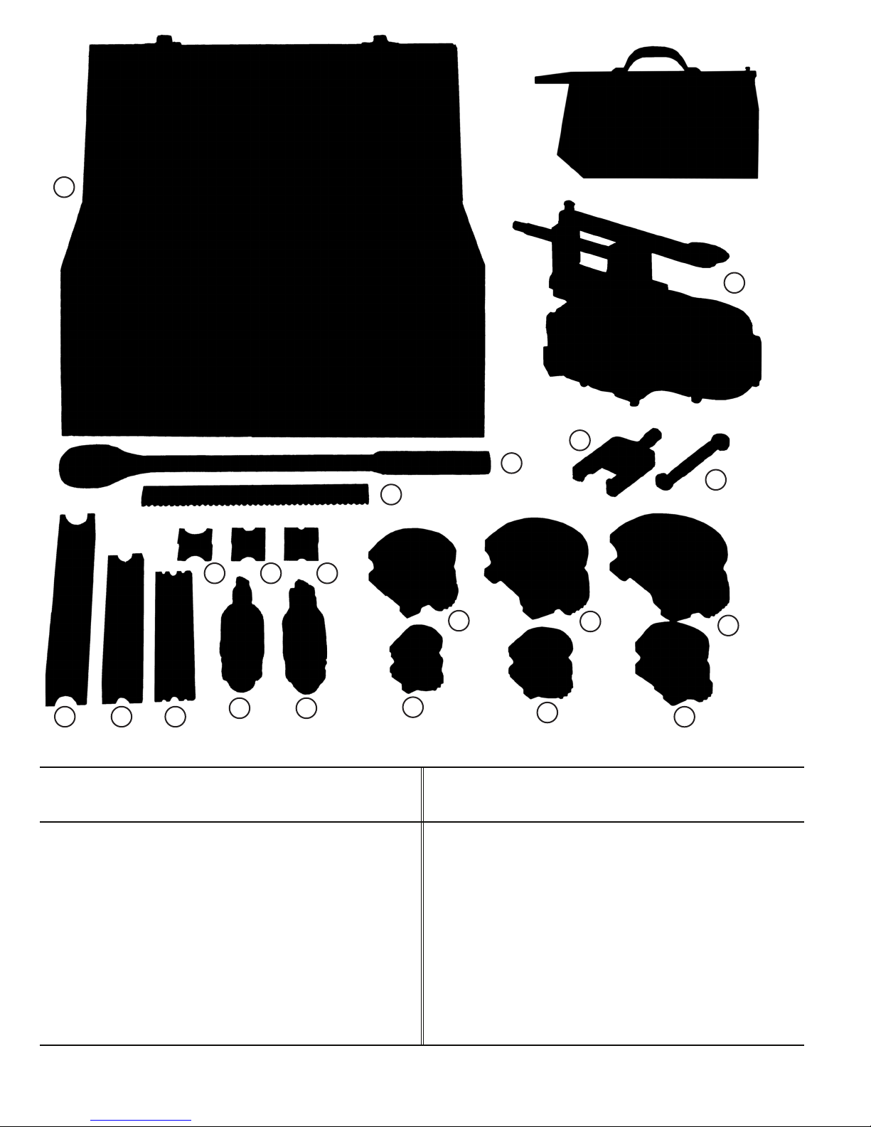
SECTION II
REPLACEMENT PARTS LIST
Figure
and
Index
No.
Imperial
Part No. Part Description Qty.
Figure
and
Index
No.
Imperial
Part No. Part Description Qty.
12-
-1
-2
-3
-4
-5
-6
-7
-7
-7
-7
-7
-7
-8
-8
-8
-9
-10
-11
-12
-13
-13
-13
-14
-15
-16
-17
74597
74559
74560
74558
74557
74596
74569
74572
74575
74578
74581
74584
74587
74588
74589
74604
74593
74592
74591
74566
74567
74568
74565
74564
74600
74599
SCREW, No. 2 - 56x1/2".......
CAP ......................................
BUSHING .............................
PLATE ...................................
BAR .....................................
SCREW, 1/4-20x5/16".........
BLOCK GEAR ASSY.
(1/4") ..............................
BLOCK GEAR ASSY.
(5/16") ............................
BLOCK GEAR ASSY.
(3/8") ..............................
BLOCK GEAR ASSY.
(1/2") ..............................
BLOCK GEAR ASSY.
(5/8") ..............................
BLOCK GEAR ASSY.
(3/4") ..............................
BLOCK (1/4 & 5/16")...........
BLOCK (3/8 & 1/2") .............
BLOCK (5/8 & 3/4") .............
SCREW, No. 6 - 32x1/2" ......
PAD .....................................
SCREW ................................
YOKE ...................................
FORM SHOE (1/4 & 5/16")...
FORM SHOE (3/8 & 1/2") ....
FORM SHOE (5/8 & 3/4") ....
RACK ...................................
PRESSURE PLATE ...................
SCREW, No. 8 - 32x3/8" ......
DRIVE PIN ............................
2
1
1
1
1
1
1
1
1
1
1
1
1
1
1
1
1
1
1
1
1
1
1
1
2
2
12-
-18
-19
-20
-21
-22
-23
-24
-25
-26
-27
-28
-29
-30
-31
-31
-32
-33
-34
-35
-36
-37
-38
-39
-40
-41
-42
-43
-44
-45
-46
-47
74562
74563
74556
74594
74595
74543
74561
74598
74532
74601
74541
61252
28843
74554
74555
74553
74550
74549
74546
74548
74552
68089
74545
74551
74547
74608
74544
74542
74609
74603
79321-01
SCREW ................................
BLOCK .................................
POST....................................
SCREW, 1/2 - 13x1-1/4" .....
LOCKWASHER .....................
BALL BEARING .....................
SUPPORT ..............................
SCREW, 3/8 - 16x3/4" ........
NAMEPLATE .........................
DRIVE SCREW, No. 4 x 5/16"...
HOUSING UPPER HALF .........
SOCKET HEAD SCREW,
1/4 - 20x1-1/4"...............
LOCKWASHER .....................
SHAFT (1/4") .......................
SHAFT (5/16 - 3/4").............
GEAR ...................................
BUSHING .............................
SPACER ................................
GEAR ...................................
KEY ....................................
COUNTER SHAFT .................
PIN ......................................
BALL BEARING .....................
SPACER ................................
SHAFT ..................................
RATCHET WRENCH ..............
BALL BEARING .....................
HOUSING LOWER HALF .......
WRENCH .............................
CARRYING CASE ASSY ........
SOCKET WRENCH
2
1
1
1
1
1
1
2
1
2
1
8
8
1
1
1
1
1
1
1
1
1
1
1
1
1
1
1
1
1
10

11
1
2
3
4
56
26 27
13
14
16 15 19 20
18
21
22
17
25
24
11
12
10
9
8
23
28
31
32
41
40
39 38
37
42
45
47
46
30
29
44
43
36
33 34 35
Figure 12. Tube Bender Assembly

P0000007 revB
©2008 Stride Tool Inc.
Printed in U.S.A.Printed in U.S.A.
30333 Emerald Valley Parkway • Glenwillow, Ohio 44139 USA
Table of contents