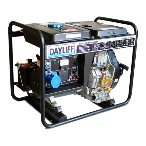
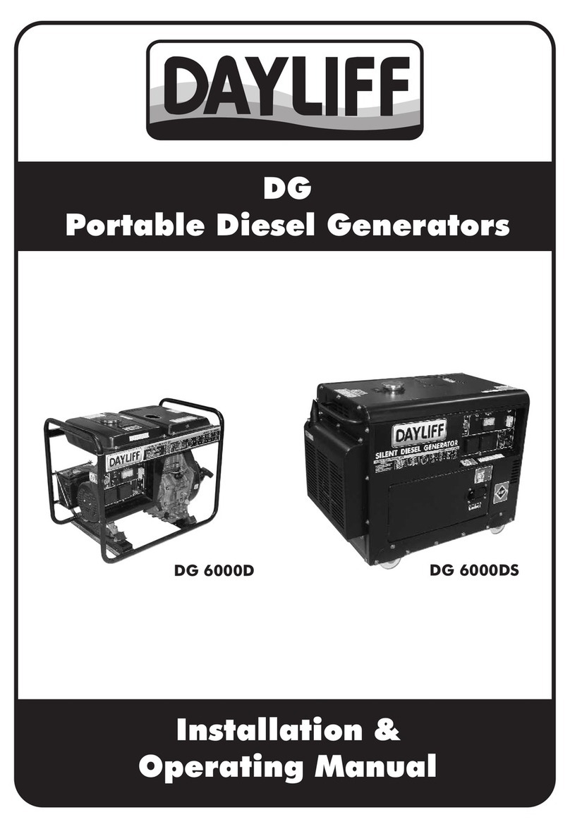
DAYLIFF DGW 200P Installation instructions

DGW
Installation &
Operating Manual
Welding Generator


GENERATOR SPECIFICATIONS
1.
1
2.
SYMBOLS & WARNINGS 3
OPERATION
3.
5
MAINTENANCE
4.
17
TROUBLE SHOOTING
5.
20
INDEX
© Davis & Shirtliff Ltd 2022
Contents herein are not warranted
WARRANTY
6.
22

1
1. GENERATOR SPECIFICATIONS
The Dayliff DGW welding generator is a dependable, quality product specially designed for
welding and generating simultaneously or separately. Particular features include:
• Options of reliable and economical air-cooled 4 stroke OHV petrol engine (DGW
200P)or high efficiency diesel engine (DGW200D ) equip ed with large size s and 300D p
exhaust and air cleaner for low noise operations.
reliable . • High efficiency square core alternator providing power output
• AC auxiliary current and DC welding current can be used simultaneously
• Strong tubular frame for protection and ease of handling.
, hourmeter• Integrated control panel with voltmeter and welding current adjuster for
operational convenience.
with breaker on indicator• Fuseless type over current protection for AC
• Engine oil level sensor for protection in case of low oil level.
• High capacity fuel tank for extended operation.
• Supplied complete with electrode holder and 4m cable, welding clamp and 4m cable,
output plugs and separate castor wheels for movable applications
DGW200 models are appropriate for use with welding rods up to 3.2mm while DGW300 is more
suited for larger rods up to 5mm depending on the welding current requirement of a given
application.
The DGW welding generator is of compact design and its advanced features make it suitable for all
small scale welding and generation applications. power
Congratulations on selecting a Dayliff DGW Welding Generator. They are
manufactured to the highest standards and if installed and operated
correctly will give many years of efcient and trouble free service. Careful
reading of this Installation Manual is therefore important, though should
there be any queries they should be referred to the equipment supplier.

2
DIMENSIONS & WEIGHTS
ELECTRICAL DATA
Alternator: self exciting, 2 pole
Power Output: 50Hz, 240V, single phase
AC Power Output: 2 No. Plug Socket+ DC Terminal Bindings for Welding Cables
Voltage Regulator: AVR
Power Factor: 1
Speed: 3000rpm
Welding Performance
No Load
Voltage (V)
Operation
Voltage (V)
Operating
Current (A)
62-68
75-80
22-26
22-32
50-130
50-270
Welding Rod Currents (A)
2.5mmØ
50-100
3.2mmØ
100-160
DGW200P
5mmØ
160-180 180-300
DGW200D
WELDING DATA
Max. Arching
Current (A)
200
180
300
Model
DGW300D
4mmØ
SPECIFICATIONS
Engine Output Fuel
Tank
Capacity
(litres)
Operating
Period
(Hrs)
Starter
Model Capacity
(cc)
Rated
Power
(HP)
Rated
(kVA)
Max
(kVA)
DGW 200P 420
418
954
10.5
7.7
17
4.5
685 520 625 107
3.0
800
1070
525
578
600
668
130
195
5
3.3
25
25
12.5
8
6
DGW 200D
Weight
(kg)
Dimensions (mm)
L W H
Engine
Model
GK420
LA186FA
LA290F
Electric
DGW 300D
All dimensions in mm
Weight: 100kgs
DERATING: Given outputs are sea level ratings. Sets should be derated at 1% for every
0 0
100m higher than 100m above sea level, and 2% for every 5 C temperature above 20 C.
H
L
W
Open Frame Type
- -

3
Part Names
Fuel Tank
Fuel Filler Cap
Air Cleaner
Recoil Starter
Starting Handle
Oil Filler Cap/Dipstick
Oil Drain Plug
Engine Control Lever
(Start/Stop Lever)
Welding Terminal
Switch
AC Output
Current Adjusting
Knob
WARNING
Check the fuel requirements and use recommended fuel
engine.
2. SYMBOLS & WARNINGS
WARNING
Wipe away all fuel spills with a clean cloth.
WARNING
Keep gasoline, kerosene, matches and other explosives and
inammables away from the generator because the
temperature around the exhaust mufer is very high during
operation.
WARNING
To prevent re hazards and to provide adequate ventilation,
keep the generator at least 1.5m away from buildings and
other equipment during operation.

4
WARNING
Operate the generator on a level surface, to avoid fuel spillage
WARNING
Exhaust gas contains poisonous carbon monoxide. Never use
the generator in poorly ventilated locations. If indoor
operation is unavoidable, provide proper ventilation.
WARNING
Never touch the mufer or mufer cover while the engine is
running as it may be hot.
WARNING
In order to avoid electric shocks or short circuit, do not touch the
generator, with wet hands.
WARNING
The generator is not waterproof, so it should not be used in a
place exposed to rain or water sprays.
CAUTION
Most appliance motors require more than their rated wattage
for start up. Do not exceed the current limit specied for any
one socket.
WARNING
The generator should be grounded to prevent electric shocks.
WARNING
Do not connect other equipment to the generator before
starting.
WARNING
Installation should be done by a qualied person in
accordance with local regulation.
WARNING
The generator should be operated by qualied personnel only.

5
PREPARATION BEFORE START
Selection and Handling Fuel
Fuel Tank: Only light diesel or gasoline can be used, The fuel must be filtered. Fuel
should be free of water or dust because these cause trouble in the fuel injection pump and
carburetor.
WARNING
Always wear a helmet, safety shoes and protective clothes.
Keep pets and children away from the generator when it is in
operation.
WARNING
Battery electrolyte contains sulphuric acid. Protect eyes, skin
and clothing. In case of contact, ush thoroughly with water
and get prompt attention, especially if eyes are affected.
WARNING
Batteries generate hydrogen gas, which can cause ames or
sparks near a battery especially during charging. Charge the
battery in a well ventilated place.
3. OPERATION
CAUTION
Do not over ll the tank beyond the top of the red plug inside
the fuel tank lter.
Air Cleaner Element: Do not wash the air cleaner element with detergent. Replace the
element when its output decreases or a bad exhaust color is noticed
CAUTION
Do not smoke or allow sparks in the area where the engine is
refueled or where gasoline is stored.
CAUTION
Do not spill fuel when refueling, make sure lter cap is securely
closed.
CAUTION
Do not refuel when the engine is running
CAUTION
After purchasing fuel, allow drum to stand 3-4 days. After
wards, put a suction pipe halfway into the drum. (Water and
dust accumulate in the lower portion of the drum).

6
Selection and handling of the lube oil
Inlet of Lubricant
Set the generator on a level ground, fill the engine oil through the inlet of lubricant.
Recommended Value
Usable Limit
ŸTo check the oil level, simply dip the dipstick into the pan. Do not screw the dipstick.
Upper Level (H)
Lower Level (H)
ŸNothing affects the performance and durability of generator more than the lube oil
used. If inferior oil is used or if it is not changed regularly, the risk of piston seizure,
piston ring sticking and accelerated wear of the cylinder liner, bearing and other
moving components increases significantly. The generator’s life may be seriously
shortened.
NOTE
Oil should rst be changed after one month or after operating
for 20 hours and thereafter every 3 months or 100 hours.
ŸBe sure to check the oil level and to refill with oil to the specified level before starting
the generator, even though it is equipped with a low oil pressure warning system.
ŸBe sure to drain the oil while the engine is warm. It is difficult to drain the oil completely
after cooling.
WARNING
The changed oil can not be used again, else damage will occur.

7
CAUTION
Do not add oil into the machine when the engine is running.
Check Air Cleaner Element
ŸLoosen the wing nut, detach the cover of air cleaner and remove the element.
ŸThe air cleaner element must be changed when the output of engine decreases or the
color of exhaust is abnormal.
Oil Drain Plug
Oil Filler Cap/Dipstick
Wing Nut
Air Cleaner
CAUTION
Do not wash air cleaner element with detergent.
CAUTION
Never run the generator without the air cleaner element. This
may cause rapid engine wear.
Element
ŸReattach the cover of air cleaner and tighten the wing nut.

8
Cover
Check Diesel Welding Machine
ŸTurn off the main switch and any other loads such as the light and motor switches.
AC Output DC Output
Starting
Switch
Circuit Breaker
Voltmeter
ŸBe sure to turn off the main switch before starting the generator. If the switch is not on
the ‘OFF’ position, sudden application of load could be very dangerous when the
diesel engine is started.
ŸThe generator should be earthed to prevent electric shocks.
Handling of dual voltage type diesel welding machine
Operation of change over switch
ŸThe circuit breaker on the control box must be used whenever AC power is to be used
and must be set to ‘OFF’ position before running the machine.
ŸStart the genset and upon attaining the rated speed turn the switch to ‘ON’ position.
ŸThe two sockets are ready to be used for output of rated voltage.
ŸSet the main switch at ‘OFF’ position when using 12V power for charge.
ŸThe terminal of 12V output can be used for 12V voltage charge user can provide a
charge switch for switch on and off.
Bleeding Fuel Line
ŸCheck fuel pipeline to find out whether there is air mixed into the pipeline. If yes, drain
away the air from the pipeline before refueling and start the diesel engine.
ŸTo do this, loosen the connection nut between injection pump and pipe line and then
drain off the air until no air bubble comes from the fuel.
Low Oil Warning System/Stop Device
ŸThis device works to stop the engine automatically when the oil pressure falls below
the recommended level and to prevent engine seizure when lube oil is running short
ŸThe oil temperature will rise too high if the engine is operated with insufficient
lubrication oil.

9
CAUTION
Avoid applying any heavy load during the break in period.
CAUTION
Change engine oil regularly.
CAUTION
Change the engine oil every 20 hours or one month after the
initial use and every 3 months or 100hours thereafter
Starting the diesel welding machine
Recoil starting (manual start)
The engine is started in the manner described below
1. Open the fuel cock (to the ‘ON’ position).
ŸOn the other hand, too much oil is dangerous because the oil may combust and
cause a sudden and excessive rise in engine revolutions, so before operating the
machine, be sure to check the oil and supply oil to the specified level.
Break In Operation
When the generator is still new, application of heavy loads may shorten the life of the
engine.

10
2. Put the engine speed lever in the ‘RUN’ position.
3. Pull out the recoil starting handle.
ŸPull out the handle to the point where it feels resistant and then return it to the initial
position.
ŸPush down the decompression lever (it will return automatically when the recoil starter
is pulled).
Engine
Speed
Lever
Decompression
Lever
ŸPull out the recoil starting handle again briskly with both hands
ŸDo not allow the handle grip to snap back against the engine. Ensure to return it gently
to prevent damage to the starter when starting or after start
CAUTION
Never pull out the start handle when diesel engine is running,
otherwise it will damage the engine.
Engine-Control Lever
Starter/Run
Stop
ŸIn cold weather, when diesel engine is difficult to start, remove the plug from the rocker
arm cover and add 2cc of engine oil.
ŸReplace the plug before starting. Keep the plug in the cover except when adding oil,
otherwise rain, dirt and other contaminants may enter the engine and cause
accelerated wear of internal parts which can cause serious problems.

11
Electric Starting
ŸOpen the fuel cock.
ŸTurn the engine control lever to‘RUN’ position.
ŸTurn the starting key at clockwise to ‘START’ position.
ŸWhen the engine starts running the key returns automatically to initial position.
ŸIf the starter motor doesn’t start after a few seconds, wait for about 15 seconds before
attempting to start again.
CAUTION
If the starter motor is run for too long, the battery will
malfuntion. Always leave the starting key turned on, in the
‘ON’ position, while the engine is running.
Plug
Engine
Speed
Lever
Battery
ŸCheck the condition of the battery whether sealed or not for cover surface damaged
or not.
ŸAlso check if Battery cable connection is sound and whether there is dust on the
exhaust vent.
ŸCheck the charging status and quality status from indicator lights, green means it’s
ok, black means there is electric loss while white means battery is damaged and needs
to be replaced.

12
Battery
Operating the generator
ŸWarm up the engine without load for about 3 minutes.
ŸThe generator is equipped with low oil warning system, and will stop automatically in
case of low oil pressure or a lubrication oil shortage. The engine also will stop if
restarted without lubrication oil . Check the oil level and refill as necessary.
ŸDo not loosen or readjust either the engine speed limiting bolt or fuel injection limiting
bolt as these are well adjusted ex-factory otherwise, performance may be affected.
During operation look out for the following warning signs
ŸAbnormal sound or vibration.
ŸThe engine misfiring or running rough.
ŸColor of the exhaust gas? (either black or white?)
If the above signs are observed stop the engine and consult the nearest Dayliff retailer.
Engine
Speed
Limiting
Bolt
Fuel Injection Limiting Bolt
Operating the Diesel Welding Machine
CAUTION
The operator must be familiar with the structure, performance,
working principle, operating procedures and precautions of
the welding unit.
CAUTION
The operator must undergo technical and safety training.
Pre-weld inspection;
ŸCheck that the welding mask does not have light leakage, damage. Welding
personnel and auxiliary personnel should wear the personal protection clothing.

13
Operating Procedures
ŸSelect the appropriate welding process (welding rod, welding current and welding
speed) and ensure it does not allow more current than maximum rated of welder
during continuous welding.
ŸThe working hours should not exceed the rated duty cycle (60%).
ŸDo not use the welding machine for metal cutting operation
ŸEnsure the welding workplace is dry and well ventilated.
ŸWhen moving the welding machine cut off the power supply and do not drag on the
floor.
ŸIncase of sudden power failure during welding, stop the generator immediately.
ŸDuring welding, do not adjust welding current. If required, stop welding and use
adjustment knob to select current.
ŸWhen welding in wet conditions, operator must stand on the insulation board and
should not touch the welding wire. Avoid using the arm clamp to hold welding clamp
as it can cause electric shock.
Maintenance
ŸAfter the welding operation is completed, the welding power supply should be cut
off immediately and the welding clamps and welding wires should be cleaned up
to avoid short circuit.
ŸWhen cleaning the weld slag, wear goggles and pay attention to the head to avoid
the direction of splashing the welding slag, so as not to stab the eyes.
ŸAfter the open operation is completed, cover the welder well for storage.
CAUTION
Load should be added according to specied parameter in
welding data guide.
ŸWelders, welding tongs, welding wires and joints should be well connected with good
insulation. Ensure there is no overheating of the wiring, the wiring terminal must not be
exposed, it requires cover with insulating tape.
ŸThe length of the wire between the welding machine and the welding clamp should be
less than10 metres, maximum length should not exceed 20 metres. Broken or damp
wires should be replaced immediately.

14
For electric principle diagram of generator, refer to the following drawing
Electrical Schematic Diagram
Dual Voltage Electrical Schematic Diagram

15
AC Application
ŸStart the engine and ensure the pilot lamp turns on. If it does not, the filament may be
burnt out.
ŸThe speed of generator must reach rated speed.
ŸGenerator is ready to take on load when the indicator of voltmeter reads 230+10%
(50Hz) on the panel of control box.
ŸPlug in the appliance.
CAUTION
Be sure that all appliance are in good working condition
before connecting them to the generating set, if an appliance
begins to operate abnormally, becomes sluggish or stops
suddenly, turn off the generating set immediately and
disconnect the appliance before examining it for signs of
malfunction.
If overloading of the circuit trips the AC circuit protector, reduce the electrical load on the
circuit and wait a few minutes before resuming operation.
If the reading on the voltmeter is too low or too high, stop the machine and examine it for
cause of malfunction.
CAUTION
Do not reverse the charging cables or serious damage to the
generator and/or battery may occur.
CAUTION
Do not allow the free ends of the cable to touch each other. If
this occurs, it will short circuit the battery.
CAUTION
When a large capacity battery is charged, excessive current
ows ( the value varies depending on the discharging
condition) and the fuse for direct current may burn out.
CAUTION
Batteries produce explosive gases. Keep sparks, ames and
cigarettes away.
DC Application
The DC terminal may be used for charging 12V automative-type batteries only
1. When using automative-type batteries with battery cables, be sure to disconnect the
negative pole battery cable from the battery before charging.
2. Start the engine.
3. Connect the charging cable to the battery terminals and the DC terminals of
generator.
4. Connect the positive battery terminal to the positive generator terminal.

16
CAUTION
To prevent the possibility of creating a spark near the battery,
always connect the charging cables to battery rst and only
then to the generator. When disconnection, you should
disconnect the cables at the generator rst
CAUTION
Charge the battery in a well ventilated place. Before charging,
remove the cap from each cell of the battery. Discontinue
0
charging if the electrolyte temperature exceeds 45 C.
CAUTION
Do not attempt to start an automobile engine while the
generator is still connected to the battery.
CAUTION
Do not use DC 12V and AC at the same time.
Stopping diesel welding machine
ŸTurn off the main switch of the diesel welding machine
ŸSet the engine control lever at the ‘RUN’ position, operate the engine without load for
about 3 minutes, do not stop the engine suddenly because this may cause the
temperature to rise abnormal and cause the nozzle to seize and damage the engine.
Engine Control Lever
ŸSet the fuel cock lever to the ‘C’ (closed) position.

17
ŸSlowly pull out the recoil handle until pressure is felt (that is, to the point in the
compression stroke where the intake and exhaust valves are closed), and leave the
handle in this position. This prevents rust from forming while the engine is not in use.
CAUTION
If the engine keeps on running even after the control lever is
locked at the ‘STOP’ position, turn the fuel oil cock to the
‘CLOSE’ position to stop the engine. Do not stop the engine with
the decompression lever.
ŸPeriodic check and maintenance are very important for keeping the engine in good
condition.
ŸThe generator consists of diesel engine, alternator, control box and frame etc.
ŸShut off the engine before performing any maintenance. If the engine must run make
sure the area is well ventilated. The exhaust contains poisonous carbon monoxide
gas.
ŸAfter engine has been used, clean it immediately with a cloth to prevent corrosion and
to remove sediment.
4. MAINTENANCE
Item
Daily
Check
(1st time) (2nd and
thereafter)
(Clean)
(Clean)
(Replace if
necessary)
(Replace)
(Replace)
(Replace)
Tighten
head bolts
(1st time)
Service more frequently when
used in dusty areas
First month
or 20hrs
Every 3months
or 100hrs
Service Period
regular
Check and replenish fuel
Drain Fuel Tank
Check and replenish lube
oil
Check for oil leakage
Check and tighten each
parts engine
Change lube oil
Clean oil lter
Air cleaner element
replacement
Clean fuel lter
Check fuel injection pump
Check fuel injection nozzle
Check fuel pipe
Adjust valve clearance for
intake and exhaust valves
Lap intake and exhaust
valves
Replace piston rings
Check battery uid
Every 6months
or 300hrs
Every year or
1000hrs
This manual suits for next models
2
Table of contents
Other DAYLIFF Portable Generator manuals
Popular Portable Generator manuals by other brands

Tektronix
Tektronix TG 2000 user manual

Jet Power
Jet Power DIESEL 115/200VAC INTRUCTION AND MAINTENANCE MANUAL
AEG
AEG LA 10 operating instructions
DUROMAX
DUROMAX XP6500E Owner's manualanual

EINHELL
EINHELL TC-PG 25/1/E5 Original operating instructions

Shindaiwa
Shindaiwa DGW310DMC Owner's and operator's manual
Ethicon
Ethicon Generator G11 Operator's manual
A-iPower
A-iPower SUA5000P owner's manual
Powermate
Powermate PM0435000 manual
Lamborghini Caloreclima
Lamborghini Caloreclima ERA F 30 B 60 instructions
Keysight
Keysight M9484C Getting Started and Troubleshooting Guide
EINHELL
EINHELL BT-PG 2000/2 operating instructions
