Daytona B917 User manual
1
B917 WHEEL BALANCER
READ THIS ENTIRE MANUAL BEFORE OPERATION BEGINS
Serial No. __________
Model No. ___B 917___

2
Warning
⚫This manual is a necessary part of the product. Please read carefully.
⚫Keep the manual for later use when maintaining the machine.
⚫This machine can only be used for the designated purposes. Never use it for any other purpose.
⚫The manufacturer is not responsible for the damage incurred by improper use or use other than the intended
purpose.
Precaution
⚫The equipment can only be operated by qualified personnel with special training. Modification to any
components or parts, or use the machine for other purpose without either obtaining the agreement from the producer,
or observing the requirement of the instructions may lead to direct or indirect damage to the equipment.
★ The equipment should be installed on the stable ground, not wooden pallet, otherwise not accurate.
⚫Keep the back panel 0.6M away from the wall for good ventilation. Enough room should be left on both
sides for convenient operation.
⚫Do not put the equipment a place with high temperature or moisture, or near the heating system, water tap,
air-humidifier or chimney.
⚫Avoid lots of dust, ammonia, alcohol, thinner or spraying binder.
⚫People who are no operating the machines should be kept away when it is used.
⚫Use appropriate equipment and tools, protective and safety equipment, including eyeglasses, earplugs and
working boots.
⚫Pay special attention to the marks on the machine.
⚫Do not touch or approach the moving parts by hand during operating.
⚫Do not remove the safety device or keep it from working properly.

3
Contents
1. General-----------------------------------------------------------------------------------------------------------------1
2. Machine assembly----------------------------------------------------------------------------------------------------1
3. Controls and components--------------------------------------------------------------------------------------------3
4. Indication and use of wheel balancer------------------------------------------------------------------------------6
5. Self-calibration of wheel balancer -----------------------------------------------------------------------------10
6. Errors------------------------------------------------------------------------------------------------------------------11
7. Self- diagnoses-------------------------------------------------------------------------------------------------------12
8. Setting machine------------------------------------------------------------------------------------------------------12
9. OPT function --------------------------------------------------------------------------------------------------------13
10. Spare parts list and Exploded drawings-------------------------------------------------------------------------15
4
1. General
1.1. Technical data:
⚫Max wheel weight:65kg
⚫Power:0.2kw;0.37kw
⚫Power supply: 220v;230v;240v;110v;50hz;60hz
⚫Balancing accuracy:
1g
⚫8balancing modes: DYN, ALU1, ALU2, ALU3, ALU4, ALU5, ALUS, ST
⚫Balancing speed:200r/min
⚫Cycle time:8s
⚫Rim diameter:10〃~24〃(256mm~610mm)
⚫Sound pressure level during work cycle:<70db
1.2. Features:
⚫ALU balancing mode may choose 9 o’clock or 12 o’clock position to add weight
⚫Statistic and dynamic balancing, ALU-programs for alloy rims or special shaped
⚫Self diagnoses, easy to find the problem
⚫Apply to steel and aluminum alloy rim
1.3. Working environment:
⚫Temperature:5~50℃
⚫Height:≤4000m
2.Machine assembly
2.1. Unpack
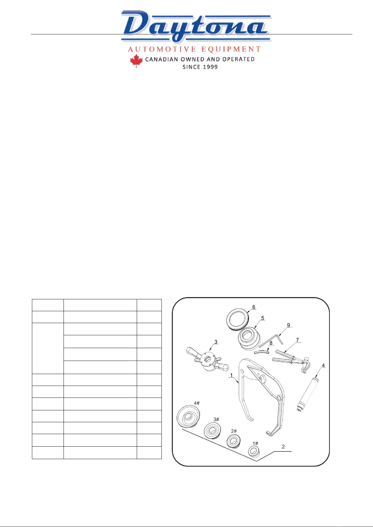
Unpack the carton, check if missing any spare parts.
No.
Item
Qty
1
Width gauge
1
2
Conic No.1
1
Conic No.2
1
Conic No.3
1
Conic No.4
1
3
Quick relase nut
1
4
Thread hub
1
5
Bowl for quick nut
1
6
Pad for bowl
1
7
Balancing hammer
1
8
100g weight
1
9
Allen wrench
1

5
2.2. Install
⚫The equipment should be installed on the stable ground, not wooden pallet, otherwise not accurate.
⚫Keep the back panel 0.6M away from the wall for good ventilation. Enough room should be left on both
sides for convenient operation.
2.3. Fix balancer to floor with screws on the bottom.
2.4. Install adaptor
The wheel balancer is supplied complete with cone type adaptor for fastening wheel with central bore. (see below
picture)
2.5. Install wheel
Clean wheel, take off counterweights, check pressure of wheel.
Choose the way of installation according to the type of wheel.
Main shaft-wheel— Main shaft-suitable cone(big head towards inside)
suitable cone( small head towards inside)—quick handle nut —wheel—quick handle nut
Attention:May add a wheel, and hold the wheel to help install the thread hub. When installing or taking off wheel,
do not let wheel move on the shaft, to avoid scratching shaft.
3.Controls and components
No.
Item
Standard/Optiona
l

6
A
Switch
S
B
Head with
tool tray
S
C
Gauge head
S
D
Main shaft
S
E
Pedal
breaker
O
F
Safe guard
S
G
Key board
S
Six balancing modes
Icon
Balancing
mode
Operation
Add weights
Standard/Default
Turn on machine
Input a,b,d value
Start spin, after spin stop
Clip on weights on
both sides of rim edge
ALU2
1. Turn on machine
2. Input a,b,d value
3. Press ALU button, indicator lit up
4. Start spin, after spin stop
Add adhesive weights
on the rim shoulder
both sides
(Button Colors May vary)

7
ALU3
1. Turn on machine
2. Input a,b,d value
3. Press ALU button, indicator lit up
4. Start spin, after spin stop
Clip on weight on
inside rim edge, add
adhesive weight on
outside rim shoulder
ALU1
1. Turn on machine
2.Input a,b,d value
3.Press ALU button, indicator lit up
4.Start spin, after spin stop
Add adhesive weights
on the rim shoulder
both sides
ALUS
1. Turn on machine
2. Press ALU button, indicator lit up
3. Input aI,aE,d value
4. Start spin, after spin stop
Add adhesive weights
on the two positions
gauge head touch
Static mode, for
motorcycle
wheels
1. Turn on machine
2. Input a,b,d value
3. Press ALU button
Start spin, after spin stop
Add adhesive weight
Key board (H)
Icon
Function
Icon
Function
Set distance
Optimization of unbalance
Set rim width
Selection of “ALU” modes
Set rim diameter
Static mode, for motorcycle wheels
“ST” Will show in right display
Recalculation
Unbalance display pitch and threshold
Start
Stop/Cancel

8
4. Indication and use of wheel balancer
4.1.DYN (Standard/Default) mode
4.1.1. Clean wheel, take off counterweights, check pressure of wheel.Choose the way of installation according to the type
of wheel.
Main shaft-wheel— Main shaft-suitable cone(big head towards inside)
suitable cone( small head towards inside)—quick handle nut —wheel—quick handle nut
Attention:May add a wheel, and hold the wheel to help install the thread hub. When installing or taking off wheel,
do not let wheel move on the shaft, to avoid scratching shaft.
4.1.2. Turn on machine
4.1.3. Input a b d value
ab
d
◼Move gauge to touch edge of rim (Fig.1), read the value of distance, press and to change,set “a”
value.
◼Use width gauge to read the value of width (Fig. 2), press and to change, set “b” value.
◼Read the value of diameter (marked on the wheel), press and set “d” value.
Fig.1 Fig.2
9
4.1.4. Put down the guard and; press to perform a measuring spin.
4.1.5. In a few seconds the wheel is brought to operating speed and begin measuring unbalance, the unbalance values
remain on instruments 1 and 3 when the wheel stopped. Press may check the real unbalance value under threshold.
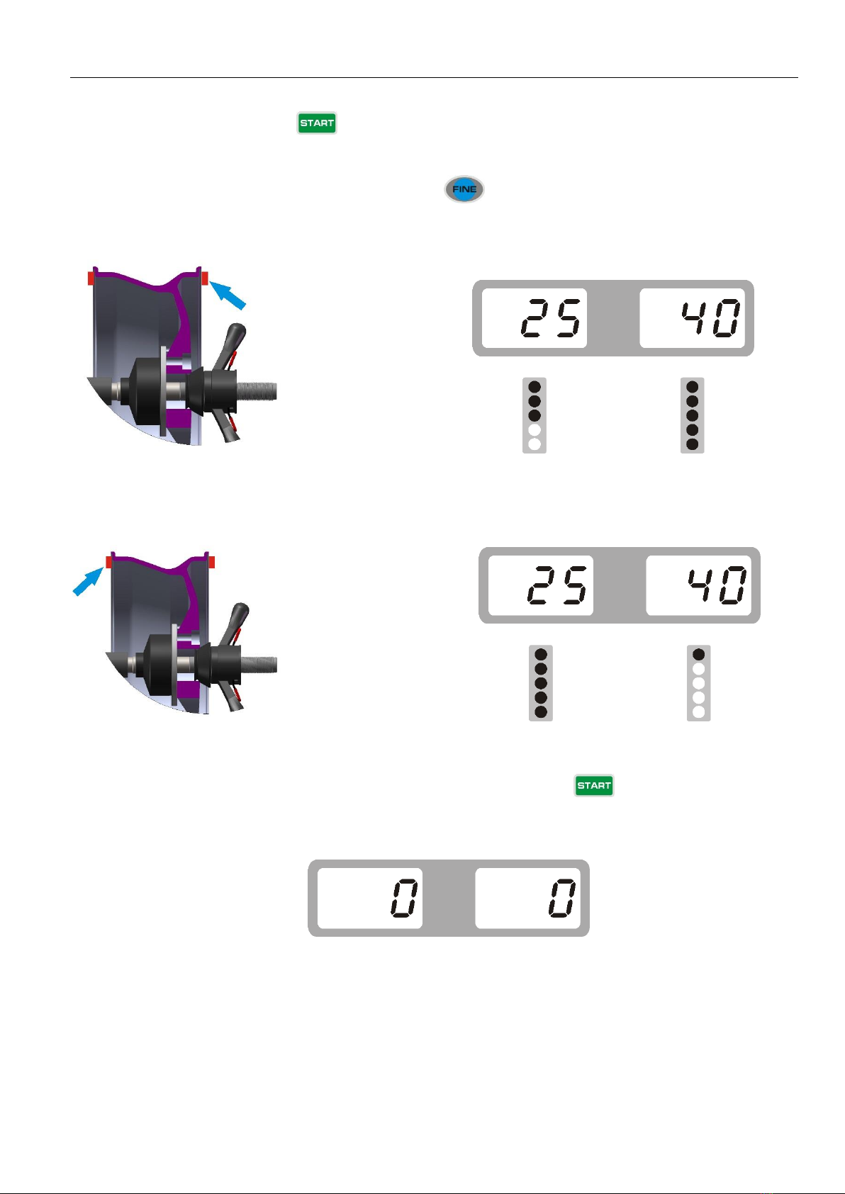
4.1.6. Anticlockwise moving wheel slowly, the displays with right LED’s lit up full indicate the correct angular position
where to mount the counterweights (12 o’clock position) outside, as Fig.3, clip the counterweight.
Fig. 3
4.1.7.Anticlockwise moving wheel slowly, the displays with left LED’s lit up full indicate the correct angular position
where to mount the counterweights (12 o’clock position) inside, as Fig.4, clip the counterweight.
Fig. 4
4.1.8. After finishing cliping the counterweights, put down the guard or press ,to perform balancing spin
again, if comes out 00 00,means balancing succeed. (Fig.5)
Fig. 5
4.2.ALU-2 mode (ALU-1, ALU3 same operation, only the position to add weights
different)
4.2.1. Set “a” “d” “b” values
10
4.2.2. Press until ALU2 indicator lit up
4.2.3. Put down the guard or press to perform a measuring spin.
4.2.4. In a few seconds the wheel is brought to operating speed and begin measuring unbalance, the unbalance values
remain on instruments 1 and 3 when the wheel stopped. Press may check the real unbalance value under threshold.
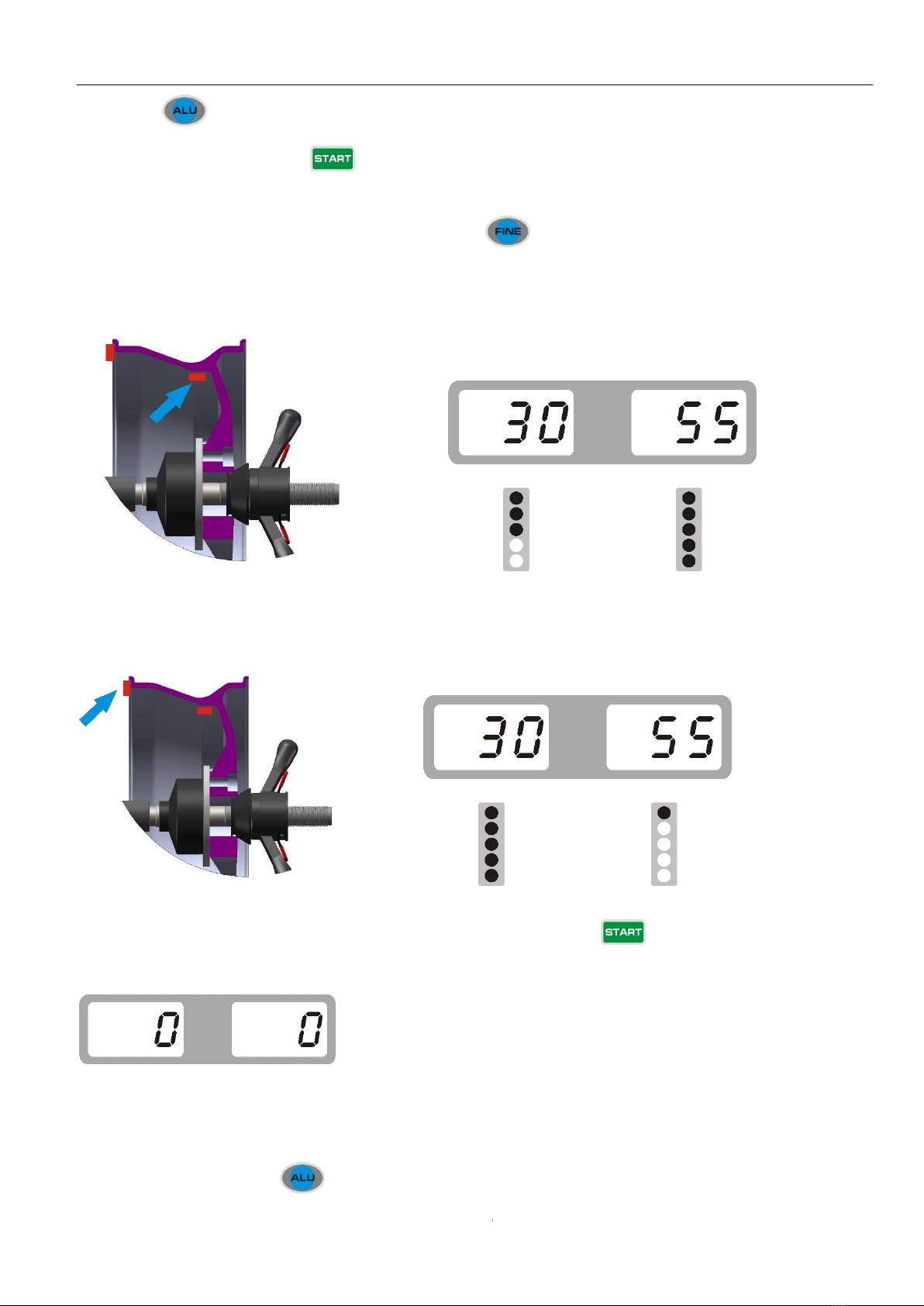
4.2.5. Anticlockwise moving wheel slowly, the displays with right LED’s lit up full indicate the correct angular position
where to mount the counterweights, 12 o’clock position (9H=Off) or 9 o’clock (9H=On) position outside, as Fig.6, add
the counterweight.
Fig. 6
4.2.6. Anticlockwise moving wheel slowly, the displays with left LED’s lit up full indicate the correct angular position
where to mount the counterweights, 12 o’clock position (9H=Off) or 9 o’clock (9H=On) position inside, as Fig.7, add the
counterweight.
Fig. 7
4.2.7. After finishing mounting the counterweights, put down the guard or press ,to perform balancing spin again,
if comes out 00 00,means balancing succeed. (Fig.8)
Fig. 8
4.3.ALU-S mode
This mode is used for special rim, if ALU1/ALU2/ALU3 can not be used, you should choose ALUS mode.
4.3.1. Turn on machine, press until the indicator of ALUS lit up.

11
4.3.2. Set aI, aE, d Value
⚫Set aI value: Pull gauge out, first to touch position of FI to measure aI value, press or to input
aI value.
⚫Set aE value :Then touch position of FE to measure aE value, press or to input aE value.
⚫Set d value: Then press and to input d value. = Inside Diameter of rim
Fig. 9
4.3.3. Put down the guard and press to perform a measuring spin. 4.3.1. 12 o’clock position to add weight
Set SLC as OFF according to 8.1
Anticlockwise moving wheel slowly, until the right LED lit up full, add weight on 12 o’clock position (Fig.10)
Fig. 10
Anticlockwise moving wheel slowly, until the left LED lit up full, add weight on 12 o’clock position (Fig.11)
Fig. 11
After finishing mounting the counterweights, put down the guard and press ,to perform balancing spin again, if
12
comes out 00 00,means balancing succeed. (Fig.12)
Fig. 12
4.3.2. Use gauge head to add weight
Set SLC as ON according to 8.1
Fig. 13
Anticlockwise moving wheel slowly, until the right LED lit up full(The inside show is the distance from the outside)
(Fig.14)
Fig. 14
Then turn down safe guard and press to start spin, comes Fig. 22 means the wheel is balanced.
Fig. 22
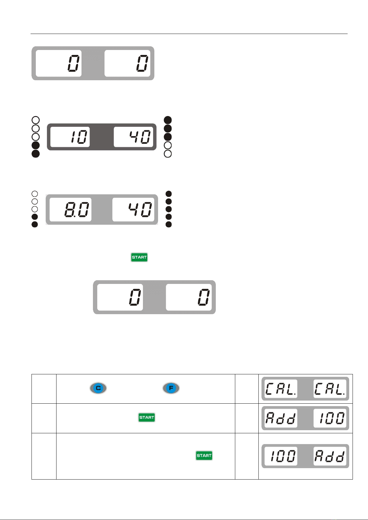
Self-calibration of wheel balancer
Do the self-calibration whenever you think the balancer is not accurate. The 100g weight must be accurate.
Turn on balancer, install a medium size wheel (13″-15″)which can use clip-on weight, set “a b d” value, then
Step 1
Press and hold, then press
comes
Step 2
Put down safe guard or press start spin, after spin stop
comes
Step 3
Open the safe guard and clip a 100 gram weight on the outside
12 o’clock position, put down safe guard and press to
start spin, after spin stop
comes

13
Step 4
Open the safe guard and clip a 100 gram weight on the inside 12
o’clock position, put down safe guard and press to start
spin, after spin stop
comes
self-calibration finished
Errors
Various abnormal conditions can arise during machined operation by the microprocessor, if comes the errors, must stop
operation, find the reason and the solution according, if the error persists, consult the supplier.
No.
Errors
Reasons
Solution
1
1.No spin
2.Shaft spin
1.If no spin, check or change power
board
2.If spin, check or change position pick
up board and computer board
3. Adjust position pick up board support
2
1.No wheel or wheel not locked
tightly
2.Position pick up board
problem
1.Lock tightly
2. check or change position pick up board
3
1.No enough pressure in wheel
2.Wheel distortion
1.Add proper pressure in wheel
2.Check wheel
4
1.Position pick up board
problem
2. Computer board problem
1.Check or change position pick up board
2.Check or change computer board
5
1. Micro switch problem
2. Computer board problem
1.Check or change Micro switch
2.Check or change computer board
6
1. Power board problem
2. Computer board problem
1.Check or change power board
2.Check or change computer board
7
1. Program lost
2. Computer board problem
1.Self calibration
2. Check or change computer board
8
1. No add 100g weight during
self calibration
2.Computer board problem
3.Power board problem
1. Add 100g weight
2.Check or change computer board
3.Check or change power board

14
9
1.Micro switch problem
2. Computer board problem
1.Check or change micro switch
2.Check or change computer board
10
1.Computer board problem
2.Power board problem
1.Check or change computer board
2.Check or change Power board
9.OPT function
Note: When unbalance value is too much, choose OPT, and operator must be experienced.
Install wheel, input a b d value
1
Press
comes>
2
Put down safe guard and press
comes>
3
With the help of tire changer, change the rim and
rubber 180 degree
reference
>
>>
4
Then put down safe guard and press
comes>
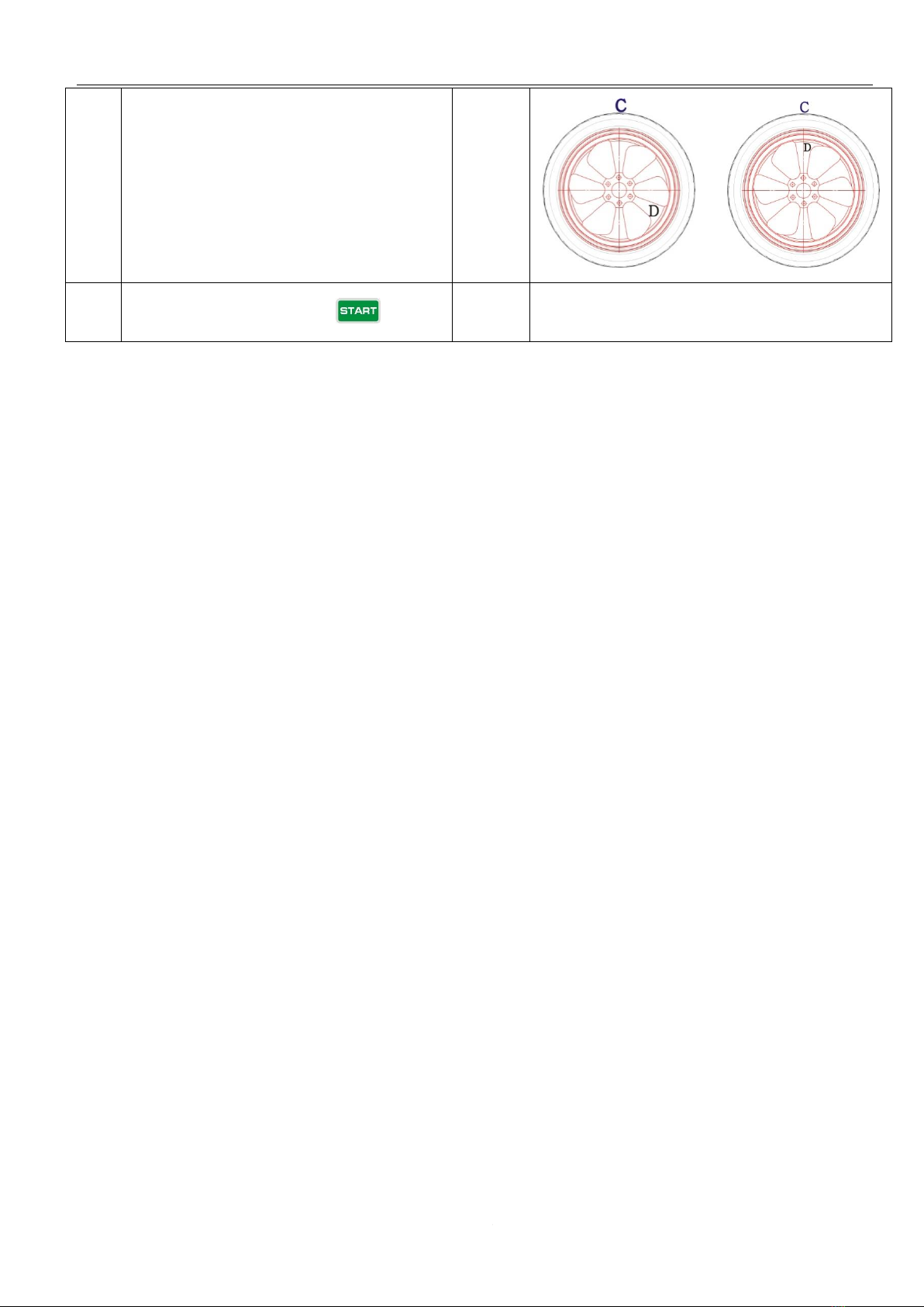
5
Rotate wheel until four indicators lit up (two on
both sides, the dark spot in the right side picture),
mark the positon C with chalk on rubber
reference
>
6
Rotate wheel until two indicators lit up (one on
both sides, the dark spot in the right side picture),
mark the positon D with chalk on rim
reference
>
15
7
With the help of tire changer, change the rim and
rubber to make C and D match
reference
>
>>
8
Put down safe guard and press
comes>
If unbalance is less than before, OPT succeed
IDENTIFYING MECHANICAL MOUNTING REPEATABILITY ERRORS ON WHEEL BALANCERS
Chasing weights, changing weight angles, changing weight amounts, and changes in run out and force variation may all be produced by
incorrect mounting or worn/damaged adaptors. Balancers cannot identify mechanical mounting errors caused by incorrect mounting
methods or worn/damaged mounting adaptors. Correct mounting MUST be verified by the technician, including identifying the on-vehicle
mounting method. Adaptors must be inspected for excessive wear and should be cleaned regularly to prevent dirt from affecting the
balancer results.
If mechanical mounting errors do not seem to be evident calibration can be performed – refer to procedures in manual.
TO TEST ELECTRONIC AND HARDWARE REPEATABILITY:
✓Mount an assembly on the spindle shaft
✓Input the weight location dimensions using standard clip-on weight locations
✓Measure and record the non-rounded amount of imbalance on each weight plane
✓Repeat this procedure four times without removing the wheel to verify the balancer can repeat measurements within 0.05
ounce (per plane). If it does not repeat the measurements, check the wheel for debris or water in the tire
TO TEST MECHANICAL MOUNTING REPEATABILITY:
✓With the assembly mounted on the spindle shaft, perform a balance spin
✓Record the non-rounded weight amounts for the inner and outer planes. (Do not apply weights)
✓When the data is recorded, loosen the wing nut and using the foot pedal to lock the spindle in position, rotate the wheel 90
degrees clockwise. Perform another balance spin. Record the non-rounded weight amounts for the inner and outer planes
✓Repeat the above steps twice more so measurements are taken at 0, 90, 180, and 270 degrees. The weight amount from
the highest to lowest recorded number should not vary by more than 0.25 ounce for smaller passenger car wheels (per plane), 0.50
ounce for SUV wheels (per plane), and 1.0 ounce for larger truck wheels (per plane). If recorded readings change by more than
this, repeat the measurements at 0, 90, 180, and 270 degrees again
DATA ANALYSIS:
Note: Larger rim/tire assemblies may experience more variation in data than smaller assemblies. This should be considered when

16
comparing data.
Do not check repeatability using ALU mode because it is “hyper-sensitive” in comparison to clip-on weight placement. In ALU mode
the diameters are smaller and the planes are closer together compared to standard clip weight balance, therefore any change in re-centering
will be amplified compared to when clip-on weight planes are dialed-in.
For example, a wheel that needs 0.25 or 0.50 oz. weights in ALU mode may show zeroes in clip-on weight mode. You can also get cases
where dynamic imbalance on standard is small, such as 1 oz., and it jumps to 4 or more oz. in ALU if the planes are close enough together.
All balancers will do this….and that’s why most balancers have such a hard time hitting zero on the first spin.
If the imbalance amounts change and the readings from the first sample data and the second sample data are NOT the same for 0, 90,
180, and 270 degrees, the assembly is not being mounted correctly. Refer to “Mounting the Wheel on the Spindle Shaft” for proper
mounting techniques.
If ALL readings change, BUT the readings from the first sample data and the second sample data are the same for 0, 90, 180, and 270
degrees, the hub/shaft assembly is out of position. Use a dial indicator to check for run out on the hub face and on the shaft. Run out on
the hub face should not exceed 0.0015”. Run out on the shaft should not exceed 0.0015”. If run out exceeds these limits, remove the
threaded hub/shaft assembly and inspect for any debris or nicks on the tapered mounting surfaces only, spindle and hub assembly must be
replaced.
BALANCER MOUNTING METHODS
MOUNTING THE WHEEL ON THE VEHICLE
Since today’s vehicles are more sensitive to road feel, it is critical to be aware of how the wheel mounts on the vehicle. Acceptable ride
quality depends on accurately mounting the wheel on the vehicle hub. Step torqueing lug nuts in a star pattern should be followed on every
installation.
If the wheel is not placed on the vehicle using the same centerline that was used on the balancer, the wheel balance, run out, and force
variation will not be duplicated.
Improper wheel centering is a huge problem when the hub bore of the wheel does not ‘slip fit’ onto the hub of the vehicle. Extra
caution should be used when mounting these types of wheels after servicing on the balancer. This is especially prevalent on lower cost
aftermarket wheels. In many cases, a tire and/or wheel is blamed for creating unacceptable vibration when in fact it was merely mounted
on the vehicle improperly.
MOUNTING THE WHEEL ON THE SPINDLE SHAFT
Since today’s vehicle designs are lighter and more sensitive to road feel, it is critical to achieve the best balance. Proper balance requires
that the tire/wheel assembly be centered on the balancer. Most balancers will balance the tire/wheel assembly to zero, even with the
tire/wheel assembly mounted off center. The main objective of the balancer operator is to center the wheel on the balancer using the best
available method. Mounting the wheel off-centre on the balancer creates incorrect measurements of imbalance and run out conditions.
MOUNTING WHEELS WITH CONES
The majority of wheels are mounted with a cone to center them on the balancer’s shaft. Cones are manufactured with different tapers.
17
The taper and the fit of the cone make a significant difference in accurate centering. Cones having a low taper fit the hub bore and guide
the wheel for better centering during the mounting process.
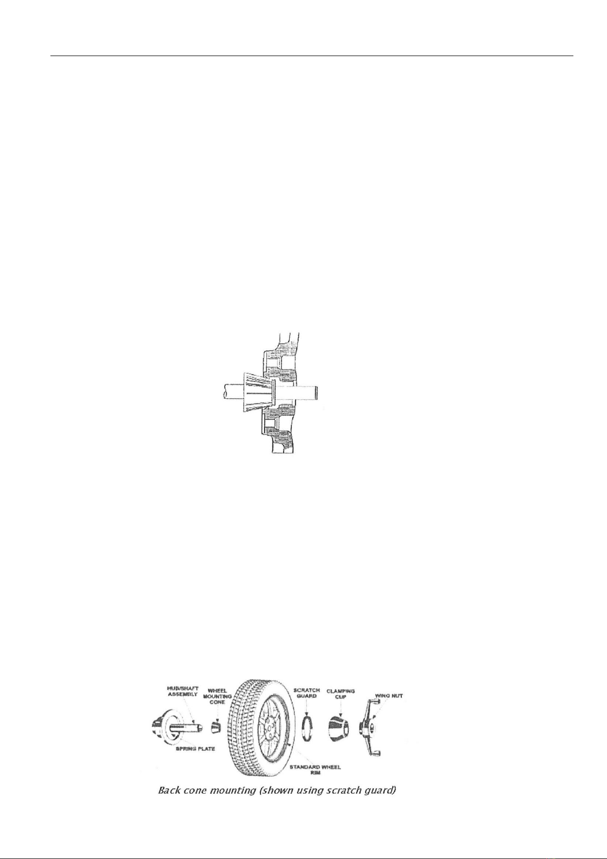
Most wheels benefit with the cone mounted from the backside. This method is referred to as back cone mounting.
CHECK FOR:
✓Correct mounting cone/adaptor for this wheel design
✓Wheel defect such as metal burr interfering with the cone/adaptor
✓Dirt or debris interfering with the cone/adaptor
BACK CONE MOUNTING PROCEDURE
Select the proper wheel-mounting cone by placing it in the center bore of the wheel to be balanced.
Select the cone that contacts the wheel nearest the center of the cone.
Place the wheel-mounting cone on the spindle against the spring plate. Mount the wheel with the inner rim facing the balancer and
centered on the cone.
Install the clamping cup and wing nut on the spindle shaft against the wheel and secure the entire assembly by firmly tightening the
wing nut. Depress the foot pedal to hold the spindle in place (if available). Slowly roll the wheel toward you during the initial tightening
of the wing nut. This helps the wheel to roll up the taper of the cone as opposed to forcing it to slide up the cone.

18
The scratch guard may be installed on the clamping cup to protect aluminum rims from being marred, but should not be used on steel
wheels.
FRONT CONE MOUNTING PROCEDURE
This procedure utilized a tapered cone inserted from the front side of the wheel instead of the backside as previously described.
Select the proper wheel-mounting cone by placing it in the center bore of the wheel to be balanced. Choose the cone that contacts
the wheel nearest the center of the cone.
Mount the wheel with the inner rim facing the balancer. Place the wheel-mounting cone on the spindle with the small end of the cone
facing the front of the wheel.
Install the wing nut and pressure ring assembly onto the spindle shaft against the wheel and secure the entire assembly by firmly
tightening the wing nut.
Heavy wheel centering may benefit by pulling the tire away from the hub face at top dead center while tightening the wing nut. This
helps the wheel to overcome gravity against the hub or spacer.
PRESSURE RING
The pressure ring should be used to prevent the wing nut from directly contacting an adaptor or a cone.
It may also be used in place of a pressure cup if space is limited between the wheel and the end of the spindle.
TIRE TECH INFORMATION/GENERAL TIRE INFORMATION

19
1. The definition of balance is the uniform distribution of mass about an axis of rotation, where the center of gravity is in the
same location as the center of rotation.
2. One of the limitations of balancing tire and wheel assemblies off a vehicle is that repeatability can be an issue. In other
words, you may not get the same results when you attempt to rebalance a wheel that has already been balanced. What has
changed? It is not the tire or rim. What has changed is the geometry of the tire and wheel on the balancer.
3. Weights on the wheel have an inherent problem due to the tire/rim geometry. Since the imbalance is normally out at the
tire tread surface, and has more effect on balance than an equal weight located at the rim radius.
4. Wheel balancers operate at a smaller radius than a wheel, making it progressively less effective as the tire diameter increase
for a given wheel diameter.
5. Match mounting tires on wheels is also a process where a tire’s installed position on the wheel is specifically selected to
help minimize the final combination’s force variation and/or imbalance.
6. Tires used off-road are notoriously hard to balance and keep balanced. They are big, they have large tread blocks (subject
to “chunking”).
7. “Lug-centric” wheels are notoriously hard to balance on common “hub-centric” balancers and are found with many different
rim manufacturers. Toyota also locates the wheel on the hub, via the rim studs. (i.e. lug-centric) and a special lug centric adaptor
should be used to properly balance the wheel.
8. According to Tru-Balance, wheel-centering products bypass the hub pilot and actually center the wheel to the wheel studs
using the 12, 4, and 8 o’clock positions, resulting in less weight value change during reposition of wheel to hub mounting on wheel
balancing machines.
9. The way that a wheel is mounted on a balancer will not only affect the accuracy of the balance job itself but also the
repeatability of the balancing results.
10. You can select different methods of wheel mounting according to practice to have wheel spin straight as possible.
POSITIVE positioning is featured with simple quick operation with suitable cone and nut on the outside of rim, commonly used
with steel rims and aluminum alloy rims with small deformation.
NEGATIVE positioning is used when deformation is noticed with the spin of the wheel. Adopt this method of positioning to
guarantee the accurate positioning of the rim inner hole and main shaft. Especially the thick ALU. Negative positioning is with
the suitable cone on the inside of the rim and the bowl and nut on the outside.
Table of contents
Popular Wheel Balancer manuals by other brands


Hofmann
Hofmann geodyna 4500-2 Operation manual

MANATEC
MANATEC JUMBO HCV operating manual

M&B Engineering
M&B Engineering WB 355 Original instruction manual

Atlas
Atlas WBT-210 quick start guide

CAR-MON
CAR-MON LFT Series quick start guide

HENNESSY INDUSTRIES
HENNESSY INDUSTRIES coats ProRide Diagnostic manual


