GB1200 User Manual
- -
8
2. Check whether input dimension is wrong, press the key R to automatically defect
the value A, L, D.
3. Check whether balancing modes accord with the tire structure. (See detailed 4.4
balancing modes)
4. Check whether the lock washer nut is tightened.
5. When dismount the tire, care is taken to carry the tire lightly and do not impact the
main shaft.
6. When balancing using balancing block with clamp, nail lightly with balance weight
on the tire edge. After balancing ends, knock it on the floor and do not knock hard
on the main shaft to avoid damaging the sensor.
5. MAINTENANCE
5.1 Self-calibration
Self-calibration is completed in the factory. When using the machine many years later and
replace the parts of machine or doubt that balancing error is much greater, self-calibrate over
again. Select a medium-sized tire (13 inches or 14 inches), install it on the main shaft, input
the value A, L, D of this tire.
Caution: Select the better tire to self-calibrate, input the correct dimension, or else result in
calibrating inaccurately.
5.1.1 Self-calibrating with a tire balanced
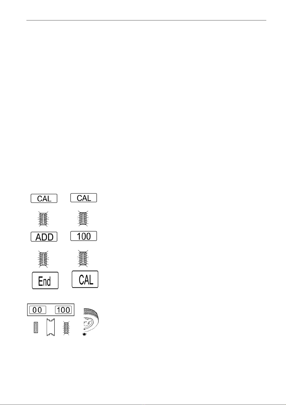
1. First press the keys R & START, the display board
displays “CAL”--“CAL”. Indicator LEDs blink; release the keys
after indicator LEDs go out.
2. Then press the key START, the wheel rotates and
automatically brakes, the display board displays “ADD”--“100”,
place 100g balancing weight at any position on the outside of
the wheel and the rim edge .
3. Then press the key START, the wheel rotates and
automatically brakes, the display board displays “END”--“CAL”,
which indicates that self-calibration ends.
4. Press the key START again, if displaying “00”--“100” (±4g)
and outer indicator LEDs blink, 100g balancing weight should
be beneath the main shaft (allow having ±4° error), which
indicates that self-calibration succeeds.
Judging self-calibration accuracy
1. Display numerical value accurately (allow having ±4° error).
2. Display phase position accurately (outer indicator LEDs blink,100g balancing weight is
beneath the main shaft and allow having ±4° error).
5.1.2 Self-calibrating with a tire unbalanced