Aston Global AWB-139CML User manual

Aston Magnetic Levitation Wheel Balancer AWB-139ML User’s Manual
www.astontechusa.com
INSTALLATION & OPERATION
USER’S MANUAL
Magnetic Levitation Wheel Balancer AWB-139CML
ASTON TECHNOLOGIES, INC.

www.astontechusa.com
1
Aston Magnetic Levitation Wheel Balancer AWB-139ML User’s Manual
TABLE OF CONTENTS
Warning……………………………………………………………………………….. 3
Owner’s Responsibility……………………………………………………………….. 3
Important Safety Instructions..………………………………………………………... 4
Start Up………………………………………………………………………………...5
Operation Instructions………………………………………………………………… 5
1.1 Display Overview………………………………………………………………… 4
1.2 Keypad Overview………………………………………………………………… 6
1.3 Key Combination Overview……………………………………………………….8
1.4 Ready to Balance a Wheel...……………………………………………………….9
1.4.1 Mounting a Wheel onto the Spin Shaft……………………………………….…9
1.4.2 Back Centering-Cone Mounting………………………………………………...9
1.4.3 Front Centering-Cone Mounting……………………………………………….10
1.4.4 Universal Adaptor Mounting (optional)………………………………………..11
1.5 Enter Wheel Data.……………………………………………………………......11
1.5.1 Manual Data Entry……………………………………………………………..11
1.5.1.1 Rim Distance A………………………………………………………………11
1.5.1.2 Rim Diameter D……………………………………………………………...12
1.5.1.3 Rim Width W…………………………………………………………………12
1.5.2 Automatic Data Entry…………………………………………………………..13
1.5.2.1 Distance A and Rim Diameter D……………………………………………..13
1.5.2.2 Rim Width W………………………………………………………………...14
1.5.2.3 User’s Data Preset……………………………………………………………14
1.6 Balance a Wheel …………………………………………………………………15
1.6.1 Standard Dynamic Balance…………………………………………………….15
1.6.2 Standard ALU Programs……………………………………………………….18
1.6.3 ALU-S Program………………………………………………………………..19

www.astontechusa.com
2
Aston Magnetic Levitation Wheel Balancer AWB-139ML User’s Manual
1.6.4 HIDE SPLIT weight program………………………………………………….22
1.6.5 OPT- Match Mount Program……..……………………………………………23
1.6.6 Static Balancing………………………………………………………………...24
1.6.7 Motorcycle wheel balancing…………………………………………………...24
2.1 Balancing Calibration…………………………………………………………….25
2.2 Distance A Calibration…………………………………………………………...26
2.3 Diameter D Calibration…………………………………………………………..26
2.4 Width W Calibration……………………………………………………………..27
3.0 System Alarm Codes..……………………………………………………………27
Warranty…………………………………………………………………………….29

www.astontechusa.com
3
Aston Magnetic Levitation Wheel Balancer AWB-139ML User’s Manual
Warning!
FAILURE TO OPERATE THIS EQUIPMENT AS DIRECTED MAY CAUSE INJURY OR
DEATH. PLEASE READ THIS ENTIRE MANUAL PRIOR TO INSTALLATION AND
OPERATION. BY USING THIS PRODUCT, YOU AGREE THAT YOU FULLY UNDERSTAND
AND COMPREHEND THE FULL CONTENTS OF THIS MANUAL. MAKE SURE ALL
OPERATORS READ AND UNDERSTAND.
Failure to follow danger, warning, and caution instructions may lead to serious personal injury or
death to operator or bystander or damage to property. Do not operate this machine until you read
and understand all the dangers, warnings and cautions in this manual.
OWNER’S RESPONSIBILITY
To maintain machine and user safety, the responsibility of the owner is to read and follow these
instructions:
•Follow all installation instructions.
•Make sure installation conforms to all applicable Local, State, and Federal Codes, Rules, and
Regulations; such as State and Federal OSHA Regulations and Electrical Codes.
•Carefully check the unit for correct initial function.
•Read and follow the safety instructions. Keep them readily available for machine operators.
•Make certain all operators are properly trained, know how to safely and correctly operate the
unit, and are properly supervised.
•Allow unit operation only with all parts in place and operating safely.
•Carefully inspect the unit on a regular basis and perform all maintenance as required.
•Service and maintain the unit only with authorized or approved replacement parts.
•Keep all instructions permanently with the unit and all decals on the unit clean and visible.

www.astontechusa.com
4
Aston Magnetic Levitation Wheel Balancer AWB-139ML User’s Manual
IMPORTANT SAFETY INSTRUCTIONS
READ BEFORE OPERATING UNIT
•Keep the machine away from moist, corrosive and hot surrounding.
•Protective goggles, safety glasses, or a face shield must be worn by the operator. Care should
be taken to see that all eye and face safety precautions are followed by the operator. ALWAYS
WEAR SAFETY GLASSES.
•Keep guards and safety features in place and in working order.
•Wear proper protective clothing. Safety toe, non-slip footwear and protective hair covering to
contain hair is recommended. Do not wear loose clothing, or jewelry when operating the
balancer.
•If an extension cord is necessary, a cord with a current rating equal to or greater than that of the
equipment should be used. Cords rated for less current than the equipment may overheat. Care
should be taken to arrange the cord so that it will not be tripped over or pulled.
•Do not disable hood cover operation, or in any way shortcut safety controls and operations.
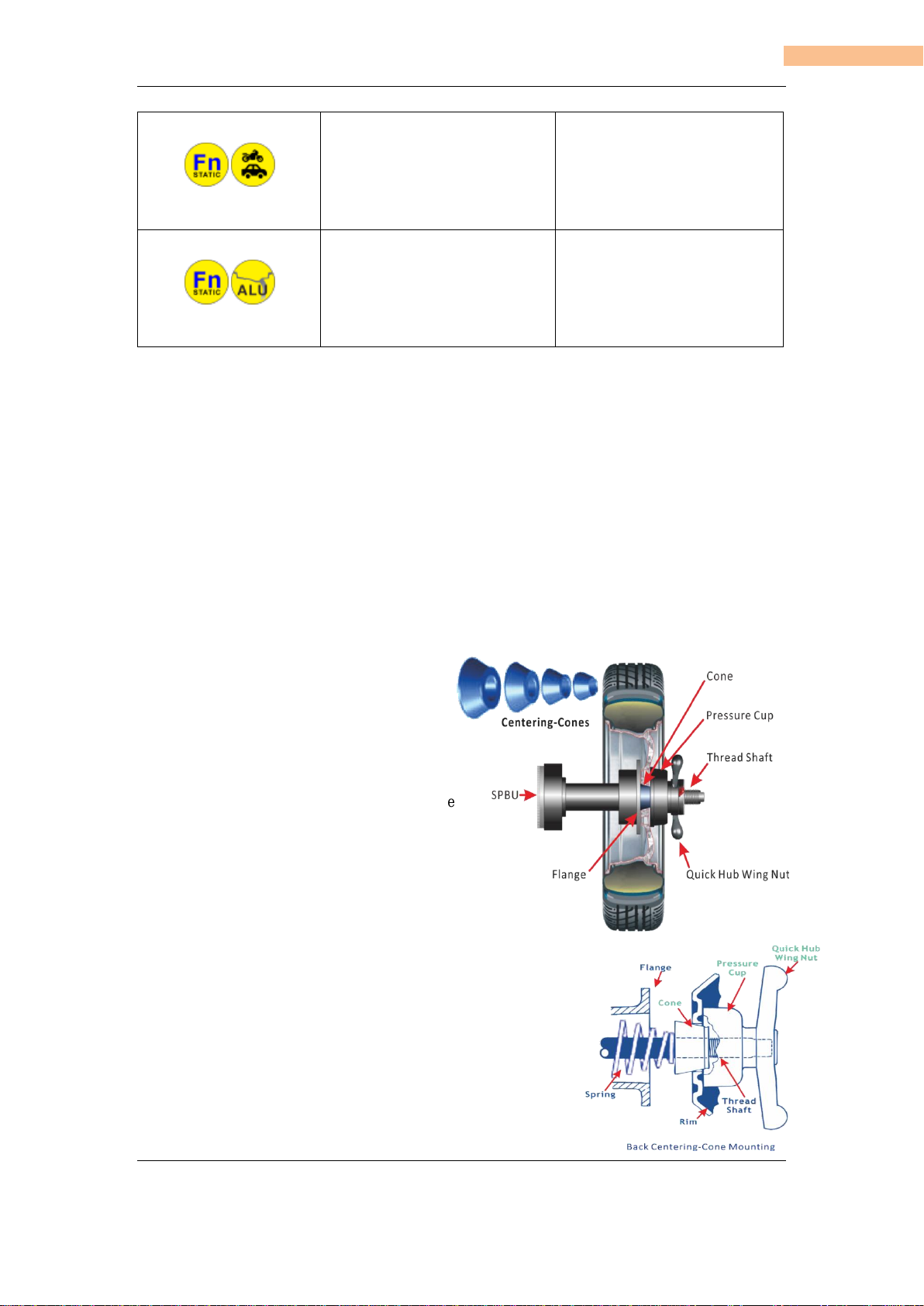
•Be sure that all wheels are mounted properly, the hub nut engages the arbor for not less than
four turns, and the hub nut is firmly tightened before spinning the wheel.
•Read and understand this manual before operating.
•Be sure the balancer is properly connected to the power supply and electrically grounded.
•Do not operate damaged equipment or if the power cord is cut or worn.
•Keep work area clean and well lighted. Cluttered and/ or dark areas invite accidents.
•Avoid dangerous environments. Do not use power tools or electrical equipment in damp or wet
locations, or expose them to rain and moisture
•Avoid unintentional starting. Be sure the balancer is turned off before servicing.
•Disconnect the balancer before servicing.
•Use only manufacturer’s recommended accessories. Improper accessories may result in
personal injury or property damage.
•Repair or replace any part that is damaged or worn and that may cause unsafe balancer operation.
Do not operate damaged equipment until it has been examined by a qualified service technician.
•Never overload or stand on the balancer.
•Do not allow untrained persons to operate machinery.
•To reduce the risk of fire, do not operate equipment in the vicinity of open containers or
flammable liquids.
•Adequate ventilation should be provided when working on operating internal combustion
engines.
•Keep hair, loose clothing, fingers, and all parts of body away from moving parts.
•Use equipment only as described in this manual.
•Use only manufacturer’s recommended attachments.

www.astontechusa.com
5
Aston Magnetic Levitation Wheel Balancer AWB-139ML User’s Manual
Start up.
1)Make sure the voltage is within the range stated in the label, and the wire is properly
grounded.
2) Switch on the wheel balancer, the system indicates as follows.
OPERATION INSTRUCTIONS
1.1. DISPLAY OVERVIEW

www.astontechusa.com
6
Aston Magnetic Levitation Wheel Balancer AWB-139ML User’s Manual
1. INNER (left) Weight Display Window.
9. OPT Function Indicator, light is on when the
Optimization Program is activated.
2. OUTER (right) Weight Display Window
10. Hidden Weight Function Indicator (under
ALU-S mode), light is on when the HIDE
Program is activated.
3. Rim Distance A Display Window.
11. Ounce Indicator, light is on when ounce (oz)
is selected.
4. Rim Width WDisplay Window.
12. Gram Indicator, light is on when gram (g) is
selected.
5. Rim Diameter DDisplay Window.
13 NA
6. User Number Indicator, light is on beside the
selected user number 1 to 4.
14 NA
7. INNER (left) Weight Position Indication
Bar.
15. Vehicle Mode Indicator, light is on beside
the corresponding vehicle type selected
8. OUTER (right) Weight Position Indication
Bar.
16. Balancing Mode Indicator, illustrates the
weight (either click-on or stick-on type)
positions corresponding to the rim profile. Refer
to the detailed balancing programs followed.
1.2. KEYPAD OVERVIEW
A
START Key: Press the START key to start
a spin cycle. Note: Lower the protection
hood to activate a spin cycle.
I
Vehicle Selection (MODE) Key:
Press this key to select the vehicle
wheel type.

www.astontechusa.com
7
Aston Magnetic Levitation Wheel Balancer AWB-139ML User’s Manual
B
STOP Key: Press STOP key to perform the
following functions in each different status:
· Stop spin cycle in emergency when the wheel is
spinning
· Activate the wheel lock (solenoid
brake) when the wheel is not spinning, deactivate it
by pressing STOP key again.
J
USER Key: Repeat pressing this
key to toggle to choose the
desired user working
environment. Press Fn+ USER
key to save presetting data in each
user environment.
C
SPL Key: Press the Smart Position Locator
key to locate the wheel to the balancing
weight position.
K
"A-" Key: Press this key to
trim down value of rim
distance A.
D
HIDE Key: Press this key to enter the
hidden weight function (behind the spokes)
when ALU-S program is activated.
L
"A+" Key: Press this key
to raise up value of rim
distance A.
E
<T Key: Press this key to indicate actual
imbalance weight amount reading below 5
grams or ¼ ounce.
M
"W-" Key: Press this key
to trim down value
of rim width W.
F
Fn / Static Key: Press this key to toggle between
dynamic and static balancing modes.
N
"W+" Key: Press this key to
raise up value of rim width W.
G
ALU Key: Press this key to ALU-S balancing
program.
O
"D-" Key: Press this key to trim
down value of rim diameter D
H
C Key: Press this key to perform t he
Following functions in each different status:
· Recalculate the balancing result after a test spin
done, after changing either of A, W and D data,
press C key to do recalculation without additional
spin;
· Exit program during in process of some
Programs.
P
"D+" Key: Press this key
to raise up value of
rim diameter D
The above listed 16 keys are all programmed with extended functions, either mode witching
or program activating. Details are shown in the following sections.

www.astontechusa.com
8
Aston Magnetic Levitation Wheel Balancer AWB-139ML User’s Manual
1.3. KEY COMBINATION OVERVIEW
KEY COMBINATION
FUNCTIONS
KEY IN PROCEDURE
Spin Mode Setting
Auto spin = Wheel spin after
protection hood is lowered down.
Manual spin = Wheel spin by
pressing START key.
In calibration program, wheel spin by
press START key.
Factory default setting is auto spin.
Press and hold the STOP key and
then press the C key, hold for 5
seconds until both weight display
windows are turned off. The spin
mode changes when keys are
released, and the display window's
lights are on. Lower the protection
hood to check spin mode status.
Weight unit setting
Set the weight units in Gram (g) or
Ounce (oz).
Press and hold the STOP key, then
press A+ and A- keys, either oz or g
indicator is illuminated upon the
selection.
Balancing Calibration
To enter the balancing calibration
program.
Press both Fn and C keys to enter
balancing calibration program.
Distance A Calibration
To enter the Distance A
calibration program.
Press Fn and A+ or A- keys to
enter Distance A calibration
program.
Width W Calibration
To enter the Width W calibration
program
Press Fn and W+ or W- keys to
enter Width W calibration
program.
Diameter D Calibration
To enter the Diameter D
calibration program.
Press Fn and D+ or D- keys to
enter Diameter D calibration
program.
Save User's Presetting
Data To preset data in each user's
environment
Press the user key to toggle to the
selected user number. Enter A, W
and D data, then press Fn and
USER keys to save data into the
selected user environment.

www.astontechusa.com
9
Aston Magnetic Levitation Wheel Balancer AWB-139ML User’s Manual
Optimization (OPT)
Program. To enter OPT
program.
Press both Fn and Vehicle-
MODE keys to enter OPT
program. See detail in the section
OPT Optimization Program.
ALU Program.
To enter ALU 1-5 programs.
Press both Fn and ALU keys to
enter ALU1-5 program. See
detail in the section ALU 1-
5Program.
1.4.Ready to balance a wheel
NOTE: Calibration is required when the wheel balancer is first put into
operation at a fixed location, after it is moved to a new location or when
the technician suspects the machine of providing incorrect values or
when main components have been replaced. It is recommended to
perform a calibration every 3 month, but especially while having
enormous possible changes of temperature during the seasons. See the
detail procedure in the calibration section.
1.4.1. MOUNTING A WHEEL ONTO THE SPIN SHAFT
Select the correct size centering-cone diameter
that will ensure the wheel rim is tightly secured
(no wobble) to the thread shaft. Insert the
centering-cone to the spin shaft and partially
through the center hole of the rim. Please pay
attention use cones and quick hub wing nut in the
different fields of application!
Below are some of the different methods for the
quick hub wing nut wheel mounting, choose the
proper one in your
application.
1.4.2. BACK CENTERING-CONE MOUNTING
Most of original equipment rims and steel rims can be handled by
using this procedure. The wheel is back-cone-centered, centering-
cone from the INNER side of the hub.

www.astontechusa.com
10
Aston Magnetic Levitation Wheel Balancer AWB-139ML User’s Manual
1)Make sure the pressure cup is attached to the quick hub wing
nut.
2)Select the centering-cone that best fits the center hole in the
rim. Slide the centering-cone over the thread shaft with the
larger diameter towards the flange, small diameter joining the
center hole of the rim.
3)Lift the wheel onto the thread shaft and center it onto the
centering-cone. Make sure to position the INNER side of the
wheel rim against the flange and cone.
4)Mount the quick hub wing nut with pressure cup onto the
thread of the spin shaft and tighten it firmly against the rim.
The quick hub wing nut should engage the threads for at least
three full turns.
NOTE
:
Use the nylon spacer between rim and pressure
cup to protect custom wheel finishes.
1.4.3. FRONT CENTERING-CONE MOUNTING
A wheel should only be centered with this method when the
type of the INNER surface of the rim is not convenient to
provide an accurate centering seat.
1)Make sure the pressure cup is NOT attached to the
quick hub wing nut.
2)Lift the wheel onto the threaded spin shaft and slide it
back against the shaft flange. Make sure to position the
INNER side of the wheel rim against the flange.
3)Slide the centering-cone onto the shaft into the middle of the
wheel rim. It is necessary to lift the wheel to get the centering-
cone placed in the center hole.
4)Fit the quick hub wing nut without pressure cup onto
the spin shaft. Tighten it securely against the centering-
cone. The hub wing nut must engage the threads for at
least three full turns.

www.astontechusa.com
11
Aston Magnetic Levitation Wheel Balancer AWB-139ML User’s Manual
1.4.4 Universal Adaptor Mounting (optional)
For wheel without center hole you must use
the optional Universal Adaptor.
For Universal Adopter details see in the
Original Equipment Manufacturer’s manual.
1.5 Enter Wheel Data
Wheel dimension data must be entered before a wheel can be balanced. There are 2 ways to
enter wheel data A, D and W, manual entry and automatic entry.
DEFINITIONS OF THE WHEEL DATA
A =Distance
The distance is measured from the wheel balancer to the
INNER plane of the rim (INNER weight location).
W =Width
The width of the rim at the rim flange.
D =Diameter
The rated diameter of the rim, it is indicated on the tire.
1.5.1. Manual Data Entry
For manual entry models, wheel data can be entered manually through the key pad.
1.5.1.1. Rim distance A
After properly mounting the wheel on the
machine spin shaft, pull out the front measuring
arm from the home position and move it to
contact on the left side of the rim. Read the
scale on the ruler to obtain the distance value
on between the machine body and the wheel.

www.astontechusa.com
12
Aston Magnetic Levitation Wheel Balancer AWB-139ML User’s Manual
Press A+ or A- key to set the distance value as per reading,
and see it shows on the rim distance A
display window.
1.5.1.2. Rim Diameter D
Read imprint for rated diameter value
from tire sidewall or rim.
Press D+ or D- key
to set the rim diameter
accordingly, and see it shows on
the rim diameter D display window.
1.5.1.3. Rim Width W
Measure width of the rim with caliper provided.

www.astontechusa.com
13
Aston Magnetic Levitation Wheel Balancer AWB-139ML User’s Manual
Press <T and W+ to activate the width data manual input.
Press W+ or W- key
to set the width value as per reading,
and see it shows on the rim distance A
display window.
1.5.2. Automatic Data Entry
For auto entry models, wheel data can be set automatically with the electronic measuring arms built
in the machine. The front measuring arm is for taking measurement of wheel distance A and rim
diameter D, and the rear measuring arm is for the rim width W
1.5.2.1. Distance Aand Rim Diameter D
Bring out the measuring arm and make the tip (stick weight holder clip) contact on the inner side of
the rim, hold it until the display windows A and D showing dashes as per the picture below.
Return the arm back to the home position, the display windows A and D are now showing the values
acquired.

www.astontechusa.com
14
Aston Magnetic Levitation Wheel Balancer AWB-139ML User’s Manual
Position of the measuring arm shall be correctly placed to ensure accurate data acquisition. If an
incorrect value has been acquired during measurement, move the arm back to home position and
repeat the operation.
1.5.2.2. Rim width W (for models equipped with sonar measuring device)
Data Acquiring Data set
Lower down the wheel guard to enter the wheel width W automatically.
Press and keys to check the value set by machine. It can be changed manually,
see the manual input section for detail.
1.5.2.3. Users Data Preset ERATE
Four different user data can be preset to the memory to save operation time.
To preset a wheel data into one of the four user environments, repeat pressing the USER key to
toggle to a desired user working environment (for example user 2), the corresponding user
number is illuminated, as illustrated in the picture followed, enter wheel data A, W and D
manually or with the automatic measuring arms, simultaneously press Fn and USER key, the
user 2-wheel data are now preset stored to the memory.
1.6 Balance a Wheel
1.6.1 Standard Dynamic Balance

www.astontechusa.com
15
Aston Magnetic Levitation Wheel Balancer AWB-139ML User’s Manual
The wheel balancer sets standard dynamic balancing as default mode. As shown in the picture,
the balancing mode indicator is in standard dynamic balancing mode, which shows clip on type
weights are to be fitted on both sides of the rim flange.
Operation steps
ASet wheel data A, W and D.
BSpin the wheel PERATE
Lower the protection hood, the wheel spins automatically, as the wheel spins, all indicators and
display windows on the display panel are turned off until the wheel stops, the balancing results
are indicated on both weight display windows as illustrated in the picture followed.
Attention!
* Do not apply any undue stress to the machine during wheel spin to obtain most
accurate result.
* Do not operate the machine without protection hood. Never raise the protection hood
before the wheel stopped. Keep hair, loose clothing, fingers and all parts of body
away from moving parts.
* To terminate a spin process, press STOP key.
CRaise the protection hood.
DWeight position search. Two methods are available in this machine: Manual search
and Automatic search (SPL), the user can choose one of them during operation.
MANUAL POSITION SEARCH
STEP 1.To search first weight position (i.e. INNER (left) side), rotate the wheel with hand,
as indicates on the weight position indication bar, turn the wheel backward (reverse spin
direction) or forward (spin direction) until all lights of the indication bar are illuminated, hold
the wheel for about 1 second, the locking device activated to restrain the wheel in the position.

www.astontechusa.com
16
Aston Magnetic Levitation Wheel Balancer AWB-139ML User’s Manual
Indication Bar Display
Upper lights on All lights on Lower lights on
Turn wheel forward In position Turn wheel backward
12 O’clock
STEP 2:
Apply a balancing weight with displayed
amount to the INNER
plane in "TDC"
(Top Dead Center)
position of the rim.
STEP 3

www.astontechusa.com
17
Aston Magnetic Levitation Wheel Balancer AWB-139ML User’s Manual
Press STOP key to unlock the wheel (user can also turn the wheel backward ndt o unlock the
wheel), search 2 weight position (i.e. OUTER (right) side) with the same way described on step
STEP 4
Apply a balancing weight with displayed amount to the OUTER (right) plane in the position on
the rim at top dead center 12 o'clock.
Automatic Position Search (SPL)
STEP 1: Press the SPL key, the wheel rotates slowly, the INNER (left) weight
positioning bars are fully illuminated as the wheel stop at the s correction weight position I
NNER (left) (Top Dead Center of the rim).
STEP 2: Apply a balancing weight with displayed amount to the INNER plane in the position
onto the rim at TDC (12 o'clock)
STEP 3: Press the SPL key, the wheel rotates slowly, the OUTER (right) weight positioning
bars are fully illuminated OUTER as the wheel stop at the (right) correction weight
position OUTER (TDC of the rim).
STEP 4: Apply a balancing weight with displayed amount to the OUTER (right) plane in the
position onto the rim at TDC (12 o'clock).
(SPL might locate at a position very close to TDC due to wheel weight deviation. Slightly rotate
the wheel forwards or rearwards until you get the buzzer sound.)
Press key C to exit the SPL program.
E After balance weights applied on the wheel, lower the protection hood, and proceed a test
wheel spin to check the balancing result. The result shall be zero on both weight display
windows if correct weights are applied to the correct positions.
Press <T Key to read the precise unbalance value.
**************************************************************************************
➢During applying weights to verify the wheel balance, positioning error might happen, and
a few degrees error might cause a residual unbalance as large as 5-10 grams, especially in
case of large unbalance.
➢In practical wheel balancing operations, available counter weights are 5 grams
increments, i.e. 5, 10, 15...60 grams etc. However, an actual unbalance results might be
any grams in between, for example, when there is a 23 grams unbalance in actual, and the
program will suggest 25 grams to balance it.

www.astontechusa.com
18
Aston Magnetic Levitation Wheel Balancer AWB-139ML User’s Manual
➢The facts described above might cause an unsatisfied balancing result, if such cases happen,
it is recommended to remove the applied weights from the rim and redo the balancing.
Always check if the balancing weights (clip-on or stick-on weights) are securely applied onto
the rim. A weight not fitted securely might come off as the wheel rotates and causes dangers.
**************************************************************************************
1.6.2 Standard ALU Programs
With the rated wheel data A, W and D entered, there are 5 standard ALU modes rated available,
the different possibilities of weight application have been considered. All standard ALU
programs provide correct unbalance values while maintaining the rated geometric data A, W
and D setting of the alloy wheel.
STANDARD ALU Programs
Indicators display
Descriptions
ALU1
For both INNER and OUTER adhesive
weights to be applied inside the rim as
illustrated.
ALU2
Clip type weight to be applied for INNER
plane, and adhesive weight to be applied
inside the rim for OUTER plane as
illustrated.
ALU3
As illustrated, only adhesive weights must
be applied for INNER and OUTER planes
ALU4
Clip type weight to be applied for INNER
plane, and adhesive weight to be applied for
OUTER plane as illustrated.
ALU5
Adhesive weight to be applied inside the rim
for plane, INNER and clip type weight to be
applied for OUTER plane, as illustrated
SWITCHING ALU PROGRAMS
STEP 1: After entering the wheel standard data A, W and D, or after a Standard dynamic
balancing test is done, Press Fn and ALU key to toggle the suitable program for your
application.
STEP 2: Spin the wheel as per the procedures described in the section of standard dynamic

www.astontechusa.com
19
Aston Magnetic Levitation Wheel Balancer AWB-139ML User’s Manual
balancing.
STEP 3: Search weight as per the procedures described in the section of standard dynamic
balancing.
STEP 4: Apply balancing weights as per the selected ALU program illustrated.
STEP 5: Proceed a test spin to check the balancing correction result
⚫Laser pointer for ALU-1
For the models with laser pointer, ALU-1 program will relocate the
weight form top position (12 o’clock) to bottom position (6
o’clock). As the weight point reaches to the correction angular
position, the laser light will project on the wheel, where indicates
the correction weight to be stick on.
******************************************************************************
Some slight residual unbalances may remain at the end of the test spin due to the considerable
difference in shape that may be found on rims with same rated dimensions. Therefore, if the
standard ALU programs are not giving a satisfied balancing result, choose the variable plane
program ALU-S to have correct balancing.
******************************************************************************
1.6.3 ALU-S Program (VARIABLE PLANE PROGRAM)
This program makes it possible to apply adhesive weights in
user selected positions. It is used for maximum precision
balancing of light alloy rims that require both weights for inner
and outer planes to be applied on the inside surface of the rim.
Press ALU keys enter the programs until the light over the mark "ALU-S" illuminates, as illustrated,
3 lights on the balancing mode indicator are illuminated.
⚫WHEEL GEOMETRIC DATA ACQUISITION
Geometric data relating to the actual balancing planes rather than the rated wheel data (A, W and D
as in standard dynamic and standard ALU programs) must be entered. The balancing planes where
the adhesive weights are to be applied may be selected by user according to the specific shape of
the rim.
Table of contents
Other Aston Global Wheel Balancer manuals
Popular Wheel Balancer manuals by other brands

Snap-on Incorporated
Snap-on Incorporated MICROSCAN III quick start guide

John Bean
John Bean VPI SYSTEM II Operation instructions

Bosch
Bosch FWA 4630 Original instructions

Eagle
Eagle EB-1200 Instruction & maintenance manual

Cormach
Cormach TOUCH MEC 100 Use and maintenance manual

Corghi
Corghi PROLINE 640 manual