Rotary Lift R1090 Manual

© May 6 2021 by Vehicle Service Group. All rights reserved.
I
N
S
T
A
L
L
A
T
I
O
N
I
N
S
T
R
U
C
T
I
O
N
S
I
N
S
T
A
L
L
A
T
I
O
N
I
N
S
T
R
U
C
T
I
O
N
S
WHEEL ALIGNMENT EQUIPMENT
R1090
INSTALLATION AND SERVICE MANUAL
FOR TESTS AND CALIBRATIONS
RESERVED FOR AUTHORIZED
SERVICE CENTERS
Co11527-12

2
0 INTRODUCTION
The purpose of this manual is to provide the installer with complete instructions for the connections and calibration of the 3D wheel
alignment equipment of the “X6” series and subsequent ones, produced since 2021
The instructions for use and maintenance, reserved for the end user, are included in the specific manual supplied with the machine.
Attention! The “CALIBRATION” procedure and other special verification procedures illustrated in this manual are re-
served for specialized technical assistance personnel; for this reason, access to them is linked to a password.
This password, which must not be communicated to other people, is determined by the sequence of keys “F8;
F7; F6; F8”.

3
TABLE OF CONTENTS
1 INSTALLATION AND UPDATING OF THE PROGRAM ............................................................................................. 4
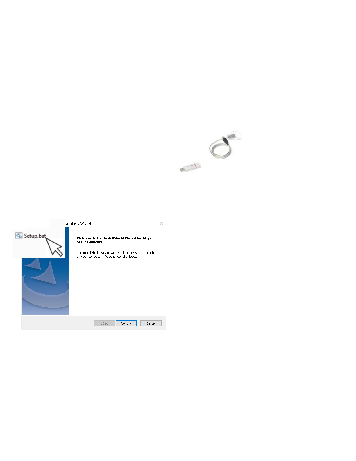
1.1. Installation........................................................................................................................................................................................................... 4
1.2. Start full installation........................................................................................................................................................................................... 4
1.3. Part 1 - Launcher installation........................................................................................................................................................................... 5
1.4. Part 2 - Prerequisite installation...................................................................................................................................................................... 5
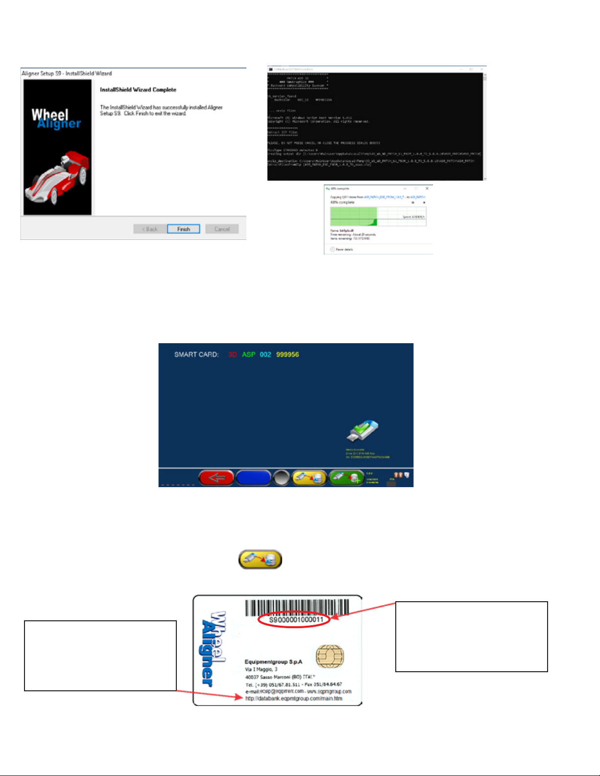
1.5. Parts 3 and 4 – Main program and installation update............................................................................................................................... 6
1.6. Uninstallation..................................................................................................................................................................................................... 8
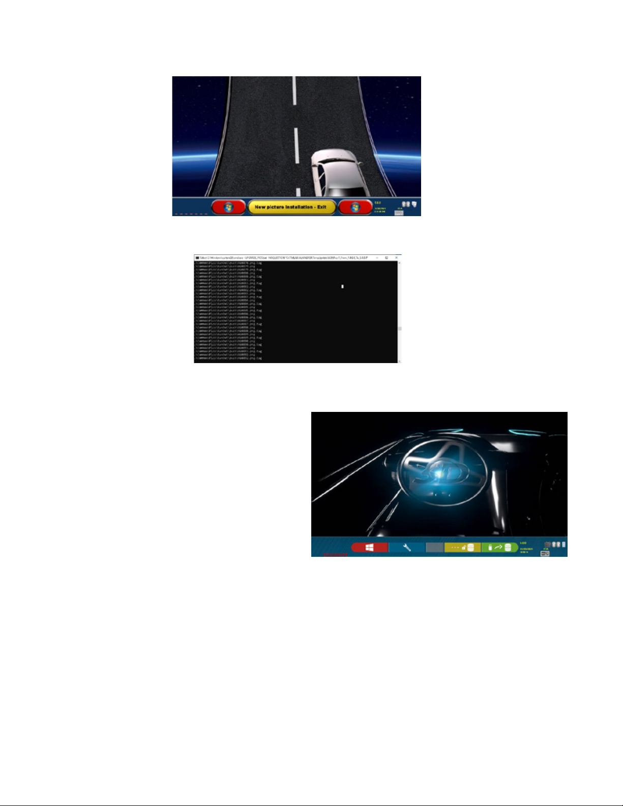
1.7. DEMO MODE ..................................................................................................................................................................................................... 8
1.8. Upgrade.............................................................................................................................................................................................................. 8
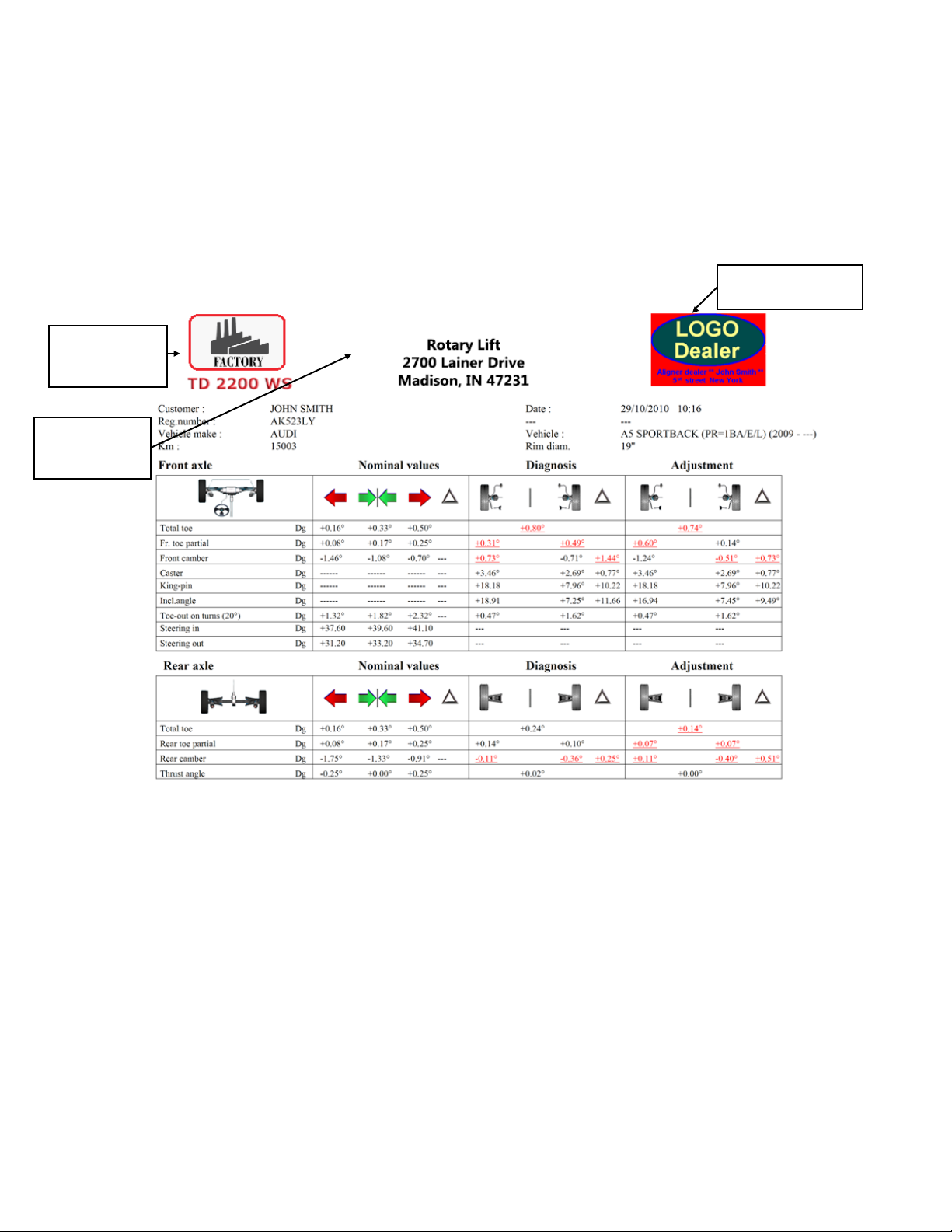
1.9. Insertion of the distributor logo...................................................................................................................................................................... 9
1.10. ATTACHING THE MEASURING HEAD SUPPORTS...................................................................................................................................... 10
2 CONNECTIONS.............................................................................................................................................................11
2.1. Power line connection..................................................................................................................................................................................... 11
2.2. Connecting the sensors to the cabinet......................................................................................................................................................... 11
2.2.1. Pairing the sensors with the cabinet............................................................................................................................................................ 12
2.3. Entering target characterization files........................................................................................................................................................... 14
2.3.1. Target Replacement........................................................................................................................................................................................ 15
2.4. Connecting the sensors and internal devices of the measuring heads................................................................................................. 16
2.4.1. Measuring head - main components........................................................................................................................................................... 16
2.4.2. Measuring head cover.................................................................................................................................................................................... 17
2.4.3. Replacing the CPU board .............................................................................................................................................................................. 19
2.4.4. Setting up the CPU board............................................................................................................................................................................... 20
2.4.5. FW Update........................................................................................................................................................................................................ 22
2.4.6. Replacing the side camera and light........................................................................................................................................................... 23
2.4.7. Replacing front / rear cameras and lights.................................................................................................................................................. 23
3 CALIBRATIONS........................................................................................................................................................... 24
3.1. Complete procedure with calibration tool.................................................................................................................................................. 24
3.1.1. Calibration procedure of the “Vertical” Central Cameras....................................................................................................................... 24
3.2. Incidence compensation adjustment.......................................................................................................................................................... 25
3.3. Steering wheel compensation adjustment................................................................................................................................................ 25
4 TEST PROCEDURES................................................................................................................................................... 26
4.1. Keyboard Test and FW Release................................................................................................................................................................... 26
4.2. Test of Inclinometers “X”and”Y” and central cameras “H” and “V”................................................................................................... 27
4.3. Test for displaying the positions of the spheres in the targets.............................................................................................................. 27
4.4. Test of the measurement of angles measured by the cameras............................................................................................................ 28
4.5. Testing Target and Side Camera................................................................................................................................................................. 29
4.6. Count of number of tests performed.......................................................................................................................................................... 30

4
1 INSTALLATION AND UPDATING OF THE PROGRAM
1.1. Installation
This process takes several minutes, it may require restarts.
You will install: Windows Power Shell; Microsoft SQL server; SW for the Smart Card reader; XVid Codec; .NET framework and finally the
“AS9” series setup SW.
Note: The PC, not supplied by the manufacturer (supplied by the customer), must have the following minimum characteristics:
• 1.5 GHz clock CPU; 4 GB RAM;
• 120GB HD
• 4 USB 2.0;
• Windows 10 Operating System
• 1366x768 Pixels Video Output
The Smart Card reader is supplied by the factory, it must be connected to a USB port
Turn on the PC and insert the USB key supplied with the equipment kit.
1.2. Start full installation
To install the 3D Wheel alignment equipment program, in Standard mode, it is necessary to launch the batch file Setup.bat (by double
clicking). Instead, to install THE DEMO version only (with a demo database and without connection to the sensors) it is necessary to
launch the SetupDEMO.bat file (again by double clicking).
Figure 1
Click on the “Next” key to finish the preparation phase and proceed to the installation (caution: the installation has not yet started).
The installation consists of four parts:
• Launcher (program that prepares and presides over the installation),
• Installing prerequisites,
• Main program,
• Upgrade.

5
1.3. Part 1 - Launcher installation
After launching through the setup.bat batch, the program prepares for the correct operation of the installation.
Note: Each of the four phases verifies the correctness of the installation and, if a critical problem is detected or if you want to terminate
the installation earlier, the launcher indicates what steps to follow in order to restore the initial condition.
Figure 2
Click on the “Install” button and then on the “Finish” key to end the preparation phase and proceed to the installation.
1.4. Part 2 - Prerequisite installation
The installer can automatically recognize the operating system and installed programs. Based on this, it decides which prerequisites
still need to be installed.
Figure 3
Click on the “Install” key and then on the “Finish” key to perform the prerequisite installation phase and move on to the next one.

6
1.5. Parts 3 and 4 – Main program and installation update
Figure 4
Click on the “Finish” key: this starts copying of the primary and secondary layout files to the hard disk:
Following this, the PC reboots.
After the PC has restarted, the SW of the newly installed “3D Wheel alignment” equipment is automatically started, the screen shown
below appears.
Figure 5
To complete the installation, you must now copy the “config” file contained in the USB key from the \AS9 folder to the folder on your PC
C:\TMLAB\ALIGNERS9\System\
This file is unique and exclusive to the equipment purchased and is paired with the Smartcard supplied.
To copy the aforementioned file simply press the F3 key , the “config” file of the USB key is automatically copied to the cor-
rect folder on the PC.
Indication of the “DATABASE” site
It is possible to download SW and
database updates.
It is poassible to activate the
machine
SmartCard Serial No.
The File Name “config” that charac-
terizes the equipment is linked to this
number
(e.g. config_S9000001000011.ENC)
Figure 6

7
After you have copied the “Config” file, you must restart the program again, so that the remaining files can be copied, depending on the
equipment model specified in the “Config” file.
The screen shown below appears:
Figure 7
Press the F1 key , all remaining files needed for the system are automatically copied.
Figure 8
The installation is now complete.
The program starts by displaying the screen on the side.
Figure 9
Subsequently, it is necessary to set the various options of the machine configuration and it will be necessary to define the connections
of the sensors to the cabinet. See the next chapters for details.
To conclude, it will be necessary to perform the “ACTIVATION” phase (installation of the “TOKEN” file), a circumstance in which the
DATABASE becomes operational and the warranty start date begins.
To download and install the “Token”, please refer to manual M0251, available on the “DATABANK” website (it is indicated on the last
line at the bottom of the SMARTCARD – see Figura 6 page 4).
Note: If your PC has an Internet connection, THE ACTIVATION phase can also be performed within the setup SW. In this instance,
always refer to manual M0251 available on the “DATABANK” website

8
1.6. Uninstallation
In the event of a critical error or interruption by the user, the program suggests the procedure to be followed to restore the situation
prior to installation.
In the Control Panel, select the “Programs and Features” item and uninstall the “AlignerS9” and “Aligner Launcher” programs.
When finished, restart the PC.
1.7. DEMO MODE
In a standard installation, to switch FROM NORMAL mode to DEMO mode (and vice versa), simply press keys Ctrl + D simultaneously.
In a “DEMO” installation you can choose any model from the entire range; at first, the above-mentioned page appears, select the
model and press F4 to continue.
Figure 10
1.8. Upgrade
The SW update can be downloaded from the “DATABANK” website (it is indicated on the last line at the bottom of THE SMARTCARD –
see Figura 6 page 4) where the latest version of the SW is always available.
Simply download the “Patch” which is proposed after entering your SMARTCARD number. The upgrade software of the alignment
equipment consists of some files including a file “UPGRADE.bat”. To update the SW simply double-click UPGRADE.bat

9
1.9. Insertion of the distributor logo
The wheel alignment program gives the possibility to insert in the final print (top right), a figure with the distributor logo and a related
text. The insertion procedure is as follows:
- Create a file representing the Distributor Logo by calling it “DEALER.PNG”; it must be in PNG format (300x192 pixels)
- Copy the file to the folder below:
:\TMLAB\ALIGNERS9\PrintTemplate\images
Factory logo and
fixed
model name
Customization of
the customer or
distributor
Figure 11
Dealer.png 300x192
pixels

10
1.10. ATTACHING THE MEASURING HEAD SUPPORTS
It is necessary to drill 3 holes for M8 screws on each side of the bridge, in order to fix the supports of the measuring heads, making
sure that the distance from the center of the heads to the center of the rotary plates is 1150 mm. If it is necessary to measure vehicles
with a very long wheelbase, it is possible to move the turntable forward by a further 400 mm.
The maximum distance from the rear wheels to the center of the heads is 3150 mm.
Note: Be sure to drill holes at a distance of 1150 mm on both sides of the bridge.
The level of the heads must then be adjusted through
the two M5 set screws arranged on the brackets. This
operation will be performed using the readings in the
appropriate test menu (see chapt. 4.2)
Drill 3 holes Ø 6.80 mm and thread M8 as in the
drawing below. The holes must be drilled 22.5
mm below the top of the runway.
The upper edges of the sup-
ports are 6 mm lower than top
of the runway.

11
2 CONNECTIONS
2.1. Power line connection
The alignment cabinet must be connected to the 100/240Vac 50/60Hz power line; the maximum power used is 500W.
Use the supplied power socket, located on the back of the cabinet.
ATTENTION: Do not unplug the the unit from the wall during the night as the batteries of the sensors must be recharged. For this reason,
when the equipment is switched off, the system disconnects power to the PC, monitor and dedicated electronics, but not to the battery
charging station.
2.2. Connecting the sensors to the cabinet
The cabinet of the “3D” alignment communicates with the measuring heads through a Bluetooth-compatible device inserted in a USB
port of the PC, and the corresponding Bluetooth-compatible devices located inside the heads. These must be “paired” with each other
through the procedure described below. The batteries are recharged on the charging station on the cabinet.
The charging stand wiring is connected on the
power board 18911. Disconnect the wiring from
the board before removing it
If you need to replace a charging station, be careful
when removing its wiring, it passes inside the cabinet. To
facilitate the passage of the new wiring, it is advisable to
leave a probe
Figure 12
On some models, similar to what
happens on the measuring head
(see chapt. 2.4.1), it is possible to
fine-tune the extraction force of the
batteries by adjusting the appropri-
ate grub screw.

12
2.2.1. Pairing the sensors with the cabinet
If the PC is not supplied by the manufacturer (supplied by the customer) or is replaced or formatted, the measuring heads must be
“paired” with the PC as indicated below.
The cabinet of the “3D” series alignment communicates with the heads via a Bluetooth compatible device
inserted into a USB port of the PC, and the corresponding modules mounted inside the measuring heads.
The transmission\reception mode of the “3D” system allows you to uniquely “pair” only one pair of heads, thus allowing you to be
protected from external disturbances and also to be able to use multiple equipment in the same room.
The “pairing” procedure described in the following pages is already performed at the factory. It is necessary only if the customer
obtains the PC, or if it is necessary to replace a detector or the PC as a spare one
Starting from the home, page press the F2 key to enter the System Menu, then use the F2/F3 keys to select the “System Configuration”
option and confirm with F4.
There is a USB extension cable,
only in some cabins useful for
placing the Bluetooth-compatible
device in a position not shielded
by metal walls (transmission is
better)
Bluetooth compatible device
on PC
ATTENTION: The Bluetooth USB (DONGLE) compatible device
provided by the manufacturer DOES NOT REQUIRE any installation
drivers! it is sufficient to plug it into a free USB port; the Windows
O.S. configures it automatically.
Starting from the home, page press the F2 key to enter
the System Menu, then use the F2/F3 keys to select
the “System Configuration” option and confirm with
F4.
Figure 13

13
Use the F2/F3 keys to select the “Sensor search”
option, then confirm with F4.
Turn on the sensors, then press the F5 key, the
search for the sensors will start.
The two windows show the MAC addresses of all
sensors with Bluetooth-compatible devices that
have been found.
Sensors configured as LEFT are indicated in the
LEFT window, sensors configured as RIGHT are
indicated in the RIGHT window.
If more than 2 sensors are found, select the correct
one via F2/F3, then press F4 to confirm.
When pairing is complete, the two icons at the bottom
right turn BLUE. Instead, if the pairing has not been
performed (or the front sensors are turned off) these
icons are GRAY.
Note: the icons highlighted in red indicate that the
driver SW that manages the system is not already
running
Important: to test the actual connection with the sen-
sors, use the communication test (release FW)
described in par. 4.1
Figure 14
Figure 15
Figure 16
Figure 17

14
It is necessary to enter the files with the description of the characterization of the 4 targets.
These are included in the USB memory key supplied with the equipment.
From the “System Configuration” menu page (see
Figura 13), select with keys F2/F3 the “Equipment
Configuration” option, then confirm with F4.
Barcode with target serial no.
Indication
FL /FR / RL /RR
Figure 18
2.3. Entering target characterization files
Confirm the “Equipment Configuration” option, then
select “Target File” and confirm with F4.
Enter the 13-character code reported on the back, for
all four targets;
FL = Front Left, FR = Front Right, RL = Rear Left, RR=
Rear Right.
Press F1 to confirm and exit;
The 4 target files will automatically be copied from
the USB key to the appropriate PC folder.
Figure 19

15
One of them must be applied to the target, in relation to its use:
• FL = front left;
• FR= front right;
• RR= rear right;
• RL= rear left
The replacement kit also includes a USB memory key where the specific target file can be found
2.3.1. Target Replacement
A damaged target can be replaced with a new replacement target.
When you receive a generic replacement target, included with the kit there are labels marked with the initials: FL, FR, RL
or RR.
Insert the USB memory key into the PC of the equipment. The file inside has the same name as the one written on the Bar-
code label on the back of the target. Make a note of this name, you will need it later.
Run the wheel alignment program.
Press F2 to access the configuration menu.
Figure 21
Using the keys F2 and F3, select the “system configuration” menu and confirm with F4.
Then continue as described in chapt. 2.3.

16
2.4. Connecting the sensors and internal devices of the measuring heads
The connections inside the measuring heads have already been made at the factory, therefore you should never open
them, except if you have to replace a component.
However, it is better to never remove the cover of the measuring head; in case of malfunctions, always contact the
manufacturer. However, if it is necessary to carry out simple maintenance work, ensure to return the moved parts to their
original position.
2.4.1. Measuring head - main components
TOLERANCE
INDICATOR LEDS
FRONT AND REAR
CAMERAS FRONT AND REAR
CAMERA LIGHT
ALPHANUMERIC DISPLAY
CPU BOARD
SIDE CAMERA LIGHT
BATTERY
SIDE CAMERA
BATTERY CONTACT BOARD
MAGNET FOR MAIN-
TAINING THE COUPLING
BRACKET
COUPLING BRACKET ON LIFT
It is possible to adjust the set
screw with an Allen wrench, to
fine-tune the battery removal
force
To remove the battery press
down on the side where the
adjustment set screw is

17
Remove the battery by pressing down on the side of the register, as shown in
chapt. 2.4.1, and remove the camera lid
Remove the 3 screws and remove the sheet metal from the battery cable
cover
Remove the 4 cover fixing screws
Remove the cover taking care to override the side camera LEDs
Position the cover sideways from the handle side of the measuring head
2.4.2. Measuring head cover

18
cod.202590600
Figure 22
Below is a brief descripon of the connecons on the CPU inside the measuring head.
JP1 BATTERY WIRING
JP2 SECONDARY BATTERY INPUT - NOT USED
JP6 SIDE CAMERA ILLUMINATOR WIRING
JP7 SERIAL 1 - RESERVED
JP8 SERIAL 2- RESERVED
JP10 PROGRAMMING JUMPER - RESERVED
JP11 ALPHANUMERIC DISPLAY
JP12 KEYBOARD
JP16 CAMERA WIRING (on head Left Rear Side; on head Right Front Side)
(paired with light with LONG WIRING)
JP17 SIDE CAMERA WIRING
JP18 CAMERA WIRING (on Left head Front side; on Right head Rear side)
(paired with light with SHORT WIRING)
JP27 LIGHT WIRING (on Left head Rear side; on Right head Front side)
- LONG WIRING ~240mm -
JP28 LIGHT WIRING (on head Left FRONT SIDE; on head Right rear side)
- SHORT WIRING ~80mm -
JP29 LED WIRING REG. Tolerance (on Left Head Front Side; on Right Head Rear Side)
JP30 LED WIRING REG. Tolerance (on Left Head Rear Side; on Right Head Front Side)

19
STDA133
STDA151
Take care when removing the wiring of
the cameras from the “ZIF” type connec-
tor: it is necessary to open the door. When
the wiring is then restored, close the door
CPU support fixed with 2 screws
Inclinometer board
Fixed with 3 screws
Take care to gently remove
the connectors of the lights
from the board, always pull-
ing them vertically
Be careful when inserting the lighter
connectors on the new board, observ-
ing the direction.
ATTENTION! The first time the PC is connected,
the message shown on the side will appear with
the words “Head Parameter Mismatch”: select
the option “PC HW” and confirm with F5, so that
the calibration saved in the PC is copied correctly
to the head with the new CPU, thus avoiding also
performing the complete calibration procedure of
the cameras.
2.4.3. Replacing the CPU board
It is possible to replace the main CPU board.
Warning: the CPU is always equipped with the inclinometer board,
connected to the CPU through a “flat” cable. When replacing this
unit, it is necessary to calibrate the inclinometer. Only the first steps
in which the “inclinometer” sensor is calibrated must be performed.
Note: For calibration of the inclinometer sensor only, it is possible to
use the complete tool STDA133 or even the simple plate STDA151.
You must first remove the inclinometer by unscrewing the 3 screws on the base, then remove the 2 screws securing the
CPU holder and gently remove it from its seat, then replace it with a new one, reconnecting all the wiring.

20
2. Click on the
“Run” button
1. Enter the BTH address of
the CPU to be configured 3. Close any error message indicating
the inconsistent FW
version
2.4.4. Setting up the CPU board
Run Windows File Explorer and open the folder on your PC: TMLAB/ALIGNERS9/EXE folders. run the
program “Superman.exe”
Table of contents