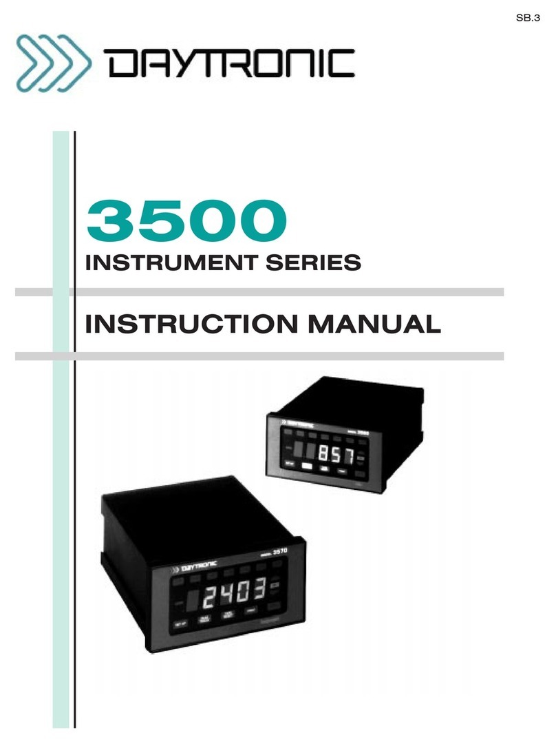
DayTronic 3000 series User manual

MODEL
3178
STRAIN GAGE CONDITIONER
SB.5.1
INSTRUCTION MANUAL
3000
Instrument Series

Copyright © 1996, Daytronic Corporation. All rights reserved.
No part of this document may be reprinted, reproduced, or used in any form or by
any electronic, mechanical, or other means, including photocopying and recording,
or in any information storage and retrieval system, without permission in writing
from Daytronic Corporation. All specifications are subject to change without notice.

Correction
to Model 3178 Instruction Manual, v. SB.5.1
The I/O Wiring Data in Fig. 4 of this manual does not give the correct shield pairing of
cable wires, which is shown in the revised diagrams below and on the following page:
1
A
2
B
3
4
C
9
A
D
B
C
+EXC
–EXC
+SENSE
–SENSE
+SIG
–SIG
CAL SENSE
C
.
.
.
A
Extra Wire, paired
with CAL SENSE,
unconnected at
Connector A
SHIELD
Daytronic 400 Series
Transducer Connections
1
A
2
B
3
4
C
9
D
A
B
C
+EXC
–EXC
+SENSE
–SENSE
+SIG
–SIG
CAL SENSE
B
.
.
.
A
Extra Wire, paired
with CAL SENSE,
unconnected at
Connector A
SHIELD
Daytronic 500 Series
Transducer Connections
1
A
2
B
3
4
7
E
B
C
D
E
+EXC
–SENSE
+SIG
–SIG
LEBOW CAL
D
.
.
.
A
Extra Wire, paired
with LEBOW CAL,
unconnected at
Connector A and
at transducer
SHIELD
A
–EXC
+SENSE
Lebow 1600 Series
Rotary Transformer Torque
Transducer Connections
(cont’d)

Correction
to Model 3178 Instruction Manual, v. SB.5.1 (cont’d)
+SENSE
–EXC
–SENSE
+SIG –SIG
CAL
SENSE
1
A
2
B
3
C
4
9
.
.
.
A
SHIELD
+EXC
Daytronic 3X78 Instrument to Generalized Strain Gage Transducer
Showing CAL SENSE Connection
4-Wire Configuration for Cables
Shorter Than 20 Feet
+SENSE
–EXC
–SENSE
+SIG –SIG
CAL
SENSE
1
A
2
B
3
C
4
9
.
.
.
A
SHIELD
Extra Wire, paired with CAL SENSE,
unconnected at Connector A
+EXC
6-Wire Configuration for Cables
Shorter Than 20 Feet
+SENSE
–EXC
+SIG –SIG
CAL
SENSE
1
A
2
B
3
C
4
9
.
.
.
A
SHIELD
Extra Wire, paired with CAL SENSE,
unconnected at Connector A
–SENSE
+EXC
8-Wire Configuration for Cables
Longer Than 20 Feet

MODEL
3178
STRAIN GAGE CONDITIONER
INSTRUCTION MANUAL
Model 3178 Instruction Manual, v. SB.5.1
Pub. No. 3178M.5.1, Issued 03/01
Part No. 91121
Daytronic Corporation
Dayton, OH • Tel (800) 668-4745
www.daytronic.com

This page intentionally blank.

Daytronic Corporation
TABLE OF CONTENTS
Section Page
1
Description................................................. 1
2
Installation and Cabling...................................... 3
3
Calibration
..................................................
11
4
Block Diagram Description 14
5
Verification of Normal Operation 19
LIST OF ILLUSTRATIONS
Figure
Page
1
Model 3178 Strain Gage Conditioner 1
2
Instrument Mounting Dimensions 4
3
Instrument Panel Mounting
5
4
I/O Wiring 9
5
Front Panel Description 12
6
Block Diagram
.............................................. 17
7
Star Bridge Construction 20
LIST OF TABLES
Table
Page
1
Specifications . . . . . . . . . . . . . . . . . . . . . . . . . . . . . . . . . . . . . . . . . . . . . . . .
2
PLEASE NOTE: Sections 6 and 7, Figures 8 and
9, and Table 2 have been
removed from this manual.
If you need information regarding specific 3178 components and circuitry,
please contact the Daytronic Service Department at (937) 293-2566.
...................................
.............................
.....................................
...........................
.............................
...................................
......................................
..................................................

Daytronic Corporation
INSTRUCTION MANUAL
MODEL 3178 STRAIN GAGE CONDITIONER
1.DESCRIPTION
The Model 3178 is a conditioner-amplifier for use with resistance strain gage
transducers in applications which require an ac excitation voltage. It supplies a 3.28
kHz
precision amplitude-regulated excitation, remotely sensed, to the transducer.
The instrument uses a phase-sensitive carrier amplifier-demodulator design so that
both direction and magnitude of the applied force are determined. The 3178 con-
tains the necessary balancing and calibration controls and conditions/amplifies the
applied input to a standard Five-Volt Data Signal Level which is the output analog
signal level of 3000 Series Instruments. Two analog outputs, having low-pass cutoff
frequencies of 2 Hz and 400 Hz, are provided. The filtered outputs provide for
averaging or smoothing of signals containing noise or other unwanted dynamic
components which are periodic in nature. Filtering removes these dynamic compo-
nents so that stable digital indication and precise jitter-free
precise jitter-free
control action can be
obtained. The Model 3178 is shown in Figure 1 and the specifications are given in
Table 1.
Figure 1. Model 3178 Strain Gage Conditioner
1

Table
1.
Specifications
Model 3178
Transducers:
4-arm bridges, 90
to
1000 ohms. nominally 0.5
mv/v
to
5
mv/v,
full scale.
Cables:
4-,
5-,
or 7-wire, depending on application; 1000
feet
maximum length.
Bridge Excitation: Regulated 3.28
kHz
ac; nominally 2
vac.
Balance Adjustments:
10-turn
coarse and fine; will balance 1.5
mv/v
initial unbalance.
Span Adjustments:
10-turn
coarse and fine; 0.5
to
5
mv/volt,
full scale.
Analog Outputs: Two
analog
outputs
available; 0
to
±5
volts
with
50%
overrange, 5 milliamperes maximum.
Bandpass
is dc to 2 Hz or dc to
400 Hz.
Active
low-pass filters provide for
rolloff
of 60
dB
per decade
above cutoff frequency. Full-scale slew time is
1.4/f
seconds, where f
is
the
cutoff frequency.
Output Ripple and Noise: 0.15% of full scale (rms) maximum for
400-Hz
output;
0.02% of full scale (rms) on
2-Hz
output.
Accuracy: 0.05% of full scale.
Dimensions: 1.7 x 4.41 x 8.5 (HWD inches).
Operating Temperature Range: 0to +130 degrees F.
Power Requirements: 105 to 135 volts
ac,
50 to 400 Hz at 5
watts
maximum.
2

Daytronic Corporation
The Model 3178 is useful in applications involving transformer coupling to the
strain gage bridge (for example, rotary transformer torque sensors) and in certain
applications that require high sensitivity with optimum signal-to-noise characteris-
tics. Carrier amplifiers offer higher sensitivity than dc amplifiers and, since they
respond only to the modulated carrier frequency, they reject certain extraneous
voltages that can cause error in dc systems. These error sources include
ther-
mocouple
or galvanic
voltages in the cable-connector system, homopolar
voltages
from rotating machinery, low-frequency
pickup, and
1/f
noises of various origin.
Consequently, the Model 3178 is an excellent instrument choice when special noise
environment conditions and the need for amplification of low-level signals exist.
Calibration of the 3178 is accomplished by the conventional shunt technique,
using an internally installed calibration resistor. Front-panel CAL buttons provide
for shunt calibration in both the positive and negative realms. An internal symmetry
control provides independent adjustment of negative realm sensitivity for trans-
ducers that do not have symmetrical slope characteristics. Positive-realm calibra-
tion can be remotely checked by means of Remote Cal terminals on the instrument
I/O connector.
The 3178 Strain Gage Conditioner is also available in two additional forms. The
Model 3278 contains a Digital Indicator to view the analog output of the conditioner.
The Model 3378 contains a Limit section (in addition to a Digital Indicator) that
provides High/OK/Low
indications and outputs. The Digital Indicator and Limit
features are standard to all 3000 Instruments and are covered in separate instruction
manuals.
2. INSTALLATION AND CABLING
The following paragraphs provide the instructions for instrument installation
and cabling.
Mounting. The 3000 Series Instruments can be operated as bench-top units or
they can be rack- or panel-mounted. Clearance dimensions for a bench-mounted
instrument are given in Figure 2. Panel cut-out dimensions for panel mounting are
also shown in Figure 2. Up to four 3000 Series Instruments can be mounted in a
19-inch
rack using the 1.75-inch high Model 3004 Rack Adaptor. Rack-mounting
dimensions are also given in Figure 2. To panel mount an instrument, proceed as
follows. Refer to Figure 3.
IMPORTANT: The unit is shipped with two spacer washers on the securing screws of the rear-panel I/O
Connector. When panel-mounting the unit, you MUST REMOVE THESE WASHERS, so that the
printed-
circuit board may move forward about
1/8" during Step (f).
3

Model 3178
A. Bench Mounting
B. Rack Mounting
C. Panel Mounting
Figure 2. Instrument Mounting Dimensions
4

Daytronic Corporation
@@
Figure 3. Instrument Panel Mounting
5

Model 3178
Remove the front panel by removing the two 2-56 x
3/8
flat-head screws.
Remove the front bezel by removing the four 6-32 x
5/8
fillister-head
screws.
Make the panel cutout and drill the screw clearance holes indicated in
Figure 2. The front bezel can be used as a template to define the
rectangular cutout and locate the clearance holes.
Hold the instrument enclosure behind the panel and reattach the front
bezel to the enclosure from the front of the panel with the four remaining
screws.
Reinstall the front panel.
Tighten the two securing screws of the rear-panel
I/O
connector to
ensure that the connector is seated and that the conditioner
printed-
circuit board is pushed fully forward so that the front-panel screwdriver
adjustments and buttons are accessible. These screws give approxi-
mately 1/8-inch of adjustment; consequently, this is the maximum panel
thickness which should be used.
CAUTION
Do not overtighten the connector securing screws or resultant
damage may occur to the printed-circuit board.
AC Power Connection. To protect operating personnel, the 3000 Series In-
struments are equipped with a three-conductor power cord. When the cord is
plugged into the appropriate receptacle, the instrument is grounded. The offset pin
on the power cord is ground. To maintain the safety ground when operating the unit
from a two-contact outlet, use a three-prong to two-prong adaptor and connect the
green pigtail on the adaptor to ground.
To prepare the instrument for operation, connect the power cable to a 105-135
volt
ac,
50-400 Hz power source. The instrument can use up to 5 watts of power.
6
(a)
(b)
(c)
(d)
(e)
(f)

Daytronic Corporation
Calibration Resistor. If a fixed resistor is shunted across one arm of a strain
gage bridge, it produces an unbalance equivalent to that of a particular value of
mechanical input. If this Equivalent Input value is accurately known, it can be used
as a reference point for shunt calibration of the system. Upon completion of
installation of the transducer and its associated cabling, the user can:
Perform an overall
dead
weight calibration using a precisely known
value of mechanical input. The calibration can then be transferred to the
installed calibration resistor for convenience in subsequent checking.
Replace the installed calibration resistor with one (or an equivalent
resistance value) supplied by the transducer manufacturer to achieve a
precisely known Equivalent Input allowing the instrument sensitivity to
be adjusted correctly.
Determine the Equivalent Input value for the installed calibration resis-
tor, knowing the transducer sensitivity, and adjust the instrument sen-
sitivity accordingly.
A precision
59-kilohm
calibration resistor is installed in the 3178 at the factory.
The installed resistor can usually be used even though the transducer calibration
data mentions some other resistance value. In Section 3 of this manual, the tech-
niques described above are demonstrated. If, however, the installed value of
calibration resistor is not appropriate for the transducer and measurement range to
be used, the
59-kilohm
resistor should be replaced at this time. The calibration
resistor is mounted on terminals located at the front edge of the conditioner
printed-circuit board. It can be accessed by removing the instrument front panel.
Note: Lebow 1600 Series Rotary Transformer Torque Transducers are supplied
with the appropriate calibration resistor integral to the transducer. When this type
of transducer is used with the 3178, it is not necessary to remove the
59-kilohm
resistor internal to the instrument. The Lebow calibration resistor can be appropri-
ately connected to the 3178 calibration circuit via the transducer cabling. Refer to
Figure 4 and the following section.
Transducer Cabling. Cabling to the transducer is accomplished via the
supplied instrument I/O connector. The I/O connector pin numbers and functions
are given in Figure 4. When Daytronic 400 or 500 Series Transducers are used,
factory-wired cables are available as shown in Figure 4. The Daytronic
82S
Cable is
for use with Lebow 1600 Series Rotary Transformer Torque Transducers. This
7
(1)
(2)
(3)

Model 3178
cable provides connection from the 3178 calibration circuit to the calibration
resistor which is integral to the 1600
Series
transducers, without requiring the
removal of the 3178 calibration resistor.
When user-fabricated transducer cabling is used, it should take the form of
either the 4-, 5-, or 7-wire cable configuration shown in Figure 4. The 4-wire
configuration should be used when overall deadweight calibration is the method
used and the required cable length is less than 20 feet. The
5-wire
configuration
should be used when the instrument is to be calibrated by achieving a precisely
known Equivalent Input value through the use of a shunt calibration resistor
supplied by the transducer manufacturer and when the required cable length is less
than 20 feet. The 7-wire configuration should be used with cable lengths longer than
20 feet since the excitation voltage is sensed and regulated at the transducer and
optimum shunt calibration can be achieved.
Remote Calibration Check. The instrument can be placed in the calibration
mode (positive realm only) by shorting pins 5 (Signal Common) and 8 (Remote Cal)
of the rear-panel I/O connector. Figure 4 indicates three methods of remotely
entering the calibration mode (external switch, transistor, or TTL source). The
Remote Cal function provides a convenient method of periodically monitoring
calibration of the instrument in the positive realm.
Master/Slave Connections. When more than one 3178 (or a combination of
3178 or 3130 LVDT Conditioners) is being used in a measurement setup (instru-
ments are continuously mounted or the transducer cabling is in a common conduit
or raceway), beat frequencies may be produced from the
3-kHz
oscillators used in
the instruments to develop the excitation. To prevent beat frequencies from occur-
ring, one unit can be designated the master, and the remaining units can be driven
from the oscillator contained in the master unit. The remaining units are designated
as
slave
instruments. To perform master/slave wiring, refer to Figure 4.
Analog Outputs. Two analog outputs are available at the instrument I/O
connector, with each output having a different passband: dc to 2 Hz and dc to 400
Hz. The cutoff frequencies are achieved with active low-pass filters. When the
dc-to-2 Hz output is used, a trade off is made between noise elimination and
increased time-to-answer or slew time. Each output has a
60-dB
rolloff
a decade
from the cutoff frequency. The filter characteristics are given by the following
equations.
8

I600
Fig. 4
I/O
Wiring Data
See the CORRECTION to Fig. 4 in the front of this manual.

I600
Fig. 4
I/O
Wiring Data
I600
Fig. 4
I/O
Wiring Data
I600
Fig. 4
I/O
Wiring Data
I600
Fig. 4
I/O
Wiring Data
I600
Fig. 4
I/O
Wiring Data
I600
Fig. 4
I/O
Wiring Data
I600
Fig. 4
I/O
Wiring Data
Fig. 4 (cont'd) See the CORRECTION to Fig. 4 in the front of this manual.

Daytronic
Corporation
Aout
@
f
0
=
0.7
Ain
Aout
@
10
f
0 = 0.001
A
in
T
=
1
.4/
f
0
where
Aout
=
output amplitude
Ain
=
input amplitude
f
0
=
selected cutoff frequency
T = time-to-answer in seconds (output of filter within 0.
1%
of final value after step function is applied).
3. CALIBRATION
This section contains the instructions for calibrating the 3178. Included is a
functional description of the instrument front-panel (see Figure 5). To perform
calibration, proceed as follows.
Turn power ON by placing the rear-panel slide switch in the ON posi-
tion. The front-panel indicator should light to indicate the application of
ac power. Allow 5 minutes of warmup for stabilization of transducer
characteristics.
Set the Fine and Coarse SPAN controls fully clockwise.
With the transducer unloaded, press the NULL button and adjust the C
BALANCE control to obtain the minimum (least positive or most nega-
tive) output reading. In some instances, an integral digital indicator will be
used to display the conditioner output (Model 3278 or 3378). When only
the conditioner is supplied
(3178),
an external indicator must be used to
monitor the conditioner output.
Release the NULL button and bring the output reading to zero with the
Fine
and Coarse R balance controls.
Load the transducer in the positive direction with a convenient dead weight
value which is greater than one half of full scale. Then remove the
3178's
front panel (one small flat-head screw near each edge) to access both the
SYMMETRY and PHASE adjustments. Adjust the PHASE control (the one
on the extreme right), until a maximum output value is obtained. Then replace
the front panel. (Once set for your transducer, this PHASE ADJUSTMENT
step need not be repeated unless a great change in cable length–or
capacitance–is required). Adjust the Coarse and Fine SPAN controls until
11
(b)
(a)
(c)
(d)
(e)

Model 3178
a
R
and C BALANCE Controls: These controls are used to set the output
to zero when the transducer is unloaded.
NULL Pushbutton: This pushbutton is pressed when
nulling
the trans-
ducer bridge with the
R
and C BALANCE controls. It provides for
non-synchronous demodulation of the carrier for balancing purposes.
After a minimum reading is obtained on the display device by adjusting
the C control, the pushbutton is released and the output
is zeroed
using
the
R
controls.
SPAN Controls: The Coarse and Fine SPAN controls are used to set the
output to the dead weight value when dead weight calibration is used.
They can also be used to set the output to the Equivalent Input value
when the CAL
(+
or –
)
button is pressed.
CAL Pushbuttons: The +and –CAL pushbuttons provide for shunt
calibration in the positive and negative realms, respectively. They are
used in conjunction with the SPAN controls to calibrate the instrument.
When both positive and negative realm calibration is required, the
+CAL button is used in conjunction with the SPAN controls and the
–CAL button is used with the internal Symmetry adjustment.
Figure 5. Front-Panel Description
12

Daytronic Corporation
the output value equals the dead weight value. Remove the dead weight, and
then press the +CAL button, noting the indicator reading obtained. In future
calibrations, you need only press the +CAL button and adjust the SPAN
controls until you obtain the previously recorded dead weight reading.
If the transducer is to be also used in the negative realm, load the
transducer in the negative direction with the same dead weight value as
used in step (e) and confirm that the dead weight reading obtained is the
same as that of step (e). If not, see steps (g) thru (i).
An internal
Symmetry
adjustment is provided to compensate for trans-
ducers that do not have symmetrical sensitivity characteristics. This
adjustment is factory set assuming symmetrical characteristics. If step
(f)
indicates that a field adjustment is necessary, proceed as follows.
Remove the front panel by removing the two 2-56 flat-head screws to
obtain access to the Symmetry adjustment.
With the transducer loaded as in step
(f),
adjust the Symmetry control (just
to the right of the –CAL button) to obtain a dead weight reading equal to
that obtained in step
(e).
If dead weight calibration is not practical and the transducer manufac-
turer has supplied a calibration resistor (or resistor value), install the
recommended calibration resistor.
Repeat steps (b) thru (d). Now press the +CAL button and adjust the
SPAN controls until the instrument output is equal to the Equivalent
Input value simulated by the installed resistor.
If a negative Equivalent Input value is also provided (as in the case of
Lebow 1600 Series transducers), press the –CAL pushbutton and con-
firm that the negative value can also be obtained with the same setting of
the Coarse
and Fine
SPAN controls. If not, adjust
the
Symmetry control
to obtain the negative Equivalent Input value.
If dead weight calibration is not practical and the transducer calibration
data is unknown, the Equivalent Input value for the factory-installed
calibration resistor can be approximated
mv/v
sensitivity rating of the transducer
known.
as follows, assuming that
and the bridge resistance
the
are
13
(f)
(g)
(h)
(i)
(j)
(k)
(l)
(m)
Other manuals for 3000 series
2
This manual suits for next models
1
Table of contents
Other DayTronic Measuring Instrument manuals
DayTronic
DayTronic 3000PLUS User manual

DayTronic
DayTronic 3770 User manual

DayTronic
DayTronic 4500 User manual
DayTronic
DayTronic M3 User manual
DayTronic
DayTronic M2 User manual

DayTronic
DayTronic 4000 Series User manual

DayTronic
DayTronic 3000PLUS User manual

DayTronic
DayTronic 3770P User manual

DayTronic
DayTronic TM3 User manual

DayTronic
DayTronic 4000 Series User manual

