DayTronic 4500 User manual

Model 4500™
Quick Reference Guide
Daytronic Corporation
2566 Kohnle Drive Miamisburg, Ohio 45342
Telephone 1-800-668-4745 or 937-866-3300
Fax 937-866-3327 www.daytronic.com

1 | Daytronic Model 4500 Quick Reference Guide
WARNING
Death, serious injury, or fire hazard could result from improper
connection of this accessory. Read and understand these instructions
and the applicable Daytronic Original Equipment User Guide before
connecting this accessory. Follow all installation and operating
instructions while using this accessory.
Connection of this instrument must be performed in compliance with the
National Electrical Code (ANSI/NFPA 70-2008) of USA and any
additional safety requirements applicable to your installation.
Installation, operation, and maintenance of this instrument must be
performed by qualified personnel only. The National Electrical Code
defines a qualified person as “one who has the skills and knowledge
related to the construction and operation of the electrical equipment and
installations, and who has received safety training on the hazards
involved.”
Qualified personnel who work on or near exposed energized electrical
conductors must follow applicable safety related work practices and
procedures, including appropriate personal protective equipment, in
compliance with the Standard for Electrical Safety Requirements for
Employee Workplaces (ANSI/NFPA 70E-2009) of USA and any
additional workplace safety requirements applicable to your installation.
Published by Daytronic Corporation
2566 Kohnle Drive
Miamisburg, Ohio 45342 USA
Telephone: 1-800-668-4745 or 937-866-3300
Fax: 937-866-3327
Web site: www. daytronic.com
Copyright ©2010 Daytronic
All rights reserved.
No part of this book may be reproduced, stored in a
retrieval system, or transcribed in any form or by any
means—electronic, mechanical, photocopying, recording,
or otherwise—without prior written permission from the
publisher Daytronic, Ohio 45342 USA.
Printed in the United States of America.
P/N QR-4500 Rev. A 04.12.10

2 | Daytronic Model 4500 Quick Reference Guide
ADVERTENCIA
Una conexión incorrecta de este instrumento puede producir la muerte, lesiones graves y
riesgo de incendio. Lea y entienda este manual antes de conectar. Observe todas las
instrucciones de instalación y operación durante el uso de este instrumento.
La conexión de este instrumento a un sistema eléctrico se debe realizar en conformidad
con el Código Eléctrico Nacional (ANSI/NFPA 70-2008) de los E.E.U.U., además de
cualquier otra norma de seguridad correspondiente a su establecimiento.
La instalación, operación y mantenimiento de este instrumento debe ser realizada por
personal calificado solamente. El Código Eléctrico Nacional define a una persona calificada
como "una que esté familiarizada con la construcción y operación del equipo y con los
riesgos involucrados."
El personal cualificado que trabaja encendido o acerca a los conductores eléctricos
energizados expuestos debe seguir prácticas y procedimientos relacionados seguridad
aplicable del trabajo incluyendo el equipo protector personal apropiado en conformidad con
el estándar para los requisitos de seguridad eléctricos para los lugares de trabajo del
empleado (ANSI/NFPA 70E-2009) de los E.E.U.U. y cualquier requisito de seguridad
adicional del lugar de trabajo aplicable a su instalación.
AVERTISSEMENT
Si l'instrument est mal connecté, la mort, des blessures graves, ou un danger d'incendie
peuvent s'en suivre. Lisez attentivement ce manuel avant de connecter l'instrument.
Lorsque vous utilisez l'instrument, suivez toutes les instructions d'installation et de service.
Cet instrument doit être connecté conformément au National Electrical Code (ANSI/NFPA
70-2008) des Etats-Unis et à toutes les exigences de sécurité applicables à votre
installation.
Cet instrument doit être installé, utilisé et entretenu uniquement par un personnel qualifié.
Selon le National Electrical Code, une personne est qualifiée si "elle connaît bien la
construction et l'utilisation de l'équipement, ainsi que les dangers que cela implique."
Le personnel qualifié qui travaillent dessus ou s'approchent des conducteurs électriques
activés exposés doit suivre des pratiques en matière et des procédures reliées par sûreté
applicable de travail comprenant le matériel de protection personnel approprié
conformément à la norme pour des conditions de sûreté électriques pour les lieux de travail
des employés (ANSI/NFPA 70E-2009) des Etats-Unis et toutes les conditions de sûreté
additionnelles de lieu de travail applicables à votre installation.
WARNUNG
Der falsche Anschluß dieses Gerätes kann Tod, schwere Verletzungen oder Feuer
verursachen. Bevor Sie dieses Instrument anschließen, müssen Sie die Anleitung lesen
und verstanden haben. Bei der Verwendung dieses Instruments müssen alle Installation-
und Betriebsanweisungen beachtet werden.
Der Anschluß dieses Instruments muß in Übereinstimmung mit den nationalen
Bestimmungen für Elektrizität (ANSI/NFPA 70-2008) der Vereinigten Staaten, sowie allen
weiteren, in Ihrem Fall anwendbaren Sicherheitsbestimmungen, vorgenommen werden.
Installation, Betrieb und Wartung dieses Instruments dürfen nur von Fachpersonal
durchgeführt werden. In dem nationalen Bestimmungen für Elektrizität wird ein Fachmann
als eine Person bezeichnet, welche "mit der Bauweise und dem Betrieb des Gerätes sowie
den dazugehörigen Gefahren vertraut ist."
Qualifiziertes Personal, das an bearbeiten oder herausgestellte angezogene elektrische
Leiter sich nähern, muß anwendbare Sicherheit bezogener Arbeit Praxis und Verfahren
einschließlich passende persönliche schützende Ausrüstung gemäß dem Standard für
elektrische Sicherheitsauflagen für Angestellt-Arbeitsplätze (ANSI/NFPA 70E-2009) der
Vereinigten Staaten und alle zusätzlichen Arbeitsplatzsicherheitsauflagen folgen, die auf
Ihre Installation anwendbar sind.

3 | Daytronic Model 4500 Quick Reference Guide
Safety Summary
Definitions
WARNING statements inform the user that certain conditions or
practices could result in loss of life or physical harm.
CAUTION statements identify conditions or practices that could harm the
Model 4500, its data, other equipment, or property.
NOTE statements call attention to specific information.
Symbols
The following International Electrotechnical Commission (IEC) symbols
are marked on the top and rear panel in the immediate vicinity of the
referenced terminal or device:
Caution, refer to accompanying documents (this guide).
Direct current (DC) operation of the terminal or device.

4 | Daytronic Model 4500 Quick Reference Guide
Safety Precautions
The following safety precautions must be followed whenever any type of
sensor connection is being made to the Model 4500.
Wear proper Personal Protective Equipment, including safety
glasses and insulated gloves when making connections to power
sensors.
Hands, shoes, and floor must be dry when making any connection
to a power line.
Before each use, inspect all cables for breaks or cracks in the
insulation. Replace immediately if defective.
Turn off the power supply to the Model 4500.
Before connecting to sensors to be monitored, open their related
circuit breakers or disconnects. DO NOT install any connection of
the Model 4500 to live power lines.
Modules should be connected first to the Model 4500, then
connected to the sensor to be monitored.
If the equipment is used in a manner not specified in this guide, the
protection provided by the equipment may be impaired.

5 | Daytronic Model 4500 Quick Reference Guide
Statements and Notices
Statement of warranty
All products of Daytronic are warranted to the original purchaser against
defective material and workmanship for a period of one year from the
date of delivery. Daytronic will repair or replace, at its option, all defective
equipment that is returned, freight prepaid, during the warranty period.
There will be no charge for repair provided there is no evidence that the
equipment has been mishandled or abused. This warranty shall not
apply to any defects resulting from improper or inadequate maintenance,
buyer-supplied hardware/software interfacing, unauthorized modification
or misuse of the equipment, operation outside of environmental
specifications, or improper site preparation or maintenance.
Statement of reliability
The information in this guide has been reviewed and is believed to be
entirely reliable, however, no responsibility is assumed for any
inaccuracies. All material is for informational purposes only and is
subject to change without prior notice.
Notice regarding proprietary rights
This publication contains information proprietary to Daytronic. By
accepting and using this guide, you agree that the information contained
herein will be used solely for the purpose of operating equipment of
Daytronic.
Copyright
This publication is protected under the Copyright laws of the United
States, Title 17 et seq. No part of this publication may be reproduced,
transmitted, transcribed, stored in a retrieval system, or translated into
any language or computer language, in any form, by any means,
electronic, mechanical, magnetic, optical, chemical, manual, or
otherwise, without the prior written consent of Daytronic, 2566 Kohnle
Drive, Miamisburg, OH 45342.
Copyright © 2010 Daytronic
All Rights Reserved. Printed in the United States of America.
Trademarks
Model 4500™is a trademark of Daytronic.

6 | Daytronic Model 4500 Quick Reference Guide
TABLE OF CONTENTS
PREFACE
Warning.................................................................................... 1
Safety Summary....................................................................... 3
Statements and Notices........................................................... 5
INTRODUCTION
Theory of Operation ................................................................. 7
DSP Section (Data Scan Function).......................................... 8
Host Section (Operator and Interfacing Management)............ 9
BASIC SETUP
Quick Setup Procedure............................................................ 11
TECHNICAL SPECIFICATIONS
Specification List ...................................................................... 17

7 | Daytronic Model 4500 Quick Reference Guide
INTRODUCTION
Theory of Operation
The Daytronic Model 4500™ is an industrial grade "intelligent" panel
instrument that measures, displays, records, controls and utilizes
computer/plc interfacing of process sensors for on-line production and
testing of manufactured parts and components for the purpose of high
speed quality verification and control. A configurable, real-time display
and touch screen interface allows for easy monitoring and interfacing in
stand-alone operations. The unit includes an external communications
port(s) that allow data retrieval and supervision by external computers
and controllers.
The Model 4500 contains two separate microprocessors subsections for
the purpose of data flow, control and interfacing. The front-end section,
referred to as the DSP, scans, data converts and manages the analog
measurement data at a sampling rate of 10KHz per analog and
mathematical calculated data channels. The interface section, referred to
as the Host, manages the communications, display, touch and other
interfacing capabilities of the instrument.
The DSP manages the A/D sampling, linearization, engineering units
conversion, mathematic calculation channels, limit control, command
control and DAC outputs of the 4500 unit. The DSP operates
independently from the Host subsection to maintain data integrity and
timing while posting data results and control parameters to the Host
section.
The Host subsection supervises the data from the DSP for the purpose
of operator display, touch control and computer interfacing of the 4500.
Areas such as the touch screen, display, RS-232 command interface,
memory management and optional items are the responsibility of the
Host section of the 4500. With this type of separated, managed
assignments between areas –DSP for obtaining and publishing the data
and the Host to manage the data flow –the 4500 has the ability to
constantly run without interruption of the data for the purpose of stand-
alone control and operation interaction.

8 | Daytronic Model 4500 Quick Reference Guide
DSP Section (Data Scan Function)
Four Analog Input Data Channels
The Model 4500 can process up to four analog input data channels from
the installed 5D Modules. Scanned and limit checked at a fixed rate of
10KHz, each input is configured by the user for the proper setup and
engineering units conversion per sensor connection for the application.
Sixteen Calculation Data Channels
Up to sixteen (16) internal calculated data channels can be configured by
the user. Calculation channels allow the unit to do cross channel
mathematics such as Maximum, Minimum, Average, RMS, Add,
Subtract, Multiply, Divide, Timers and other functions that will build the
user's application for data values. The result of the calculation channels
can be used to obtain values such as Horsepower, Efficiency, TIR,
Thickness, timer loops, Track/Hold, Peak and other useful stand-alone
channel fields. Calculation channels are updated at 10KHz rate,
including limit monitoring.
Four DAC Analog Output Data Channels
Updated at 10KHz rate, the digital to analog output channels are
available to the user to create analog representation of internal data
channels (real or calculated) for the purpose of providing the application
the benefit of analog control for external devices.
At the end of the data channel scan cycle, the DSP section will publish
the logic bit status for internal limit levels, and will check status of input
and output logic levels of the unit. With the logic level update of the bits,
the DSP section will activate logic status flags which have the ability to
activate control commands that have been configured by the user. These
command strings are accomplished via the Execute or Execute Not
syntax mnemonic. The commands configured within the Execute string
will be placed in a queue for management by the DSP or the Host
section as designated by the type of command being serviced.
Commands that affect data will be acted on by the DSP. Display and
interface commands will be acted on by the Host.

9 | Daytronic Model 4500 Quick Reference Guide
Host Section (Operator and Interfacing Management)
Touch Screen and Display
Touch screen and display operation of the unit is accomplished at a
refresh rate of approximately 4Hz. This gives the unit a reasonable
update rate enabling the user to monitor and configure the unit while
allowing the Host section to manage the tasks needed to maintain stand-
alone operation of the data acquisition process. The Host portion of the
4500 does not interrupt the DSP section, thus the unit –upon power up –
can scan and monitor the sensor and logic data regardless of whether it
is being configured, calibrated or interfaced by an external processor.
The 4500 provides users the ability to compose or develop custom
display pages for viewing depending on user application needs. The user
can select and configure any or a combination of the following elements
for the page display: data channels (real and calculated), logic bits, bar
graph representation of the data channels, trend graphs of the data
channels, touch button elements, X/Y graph of data channels, and a
notepad feature for adding instructional text or legend as required by the
application. Each of the composable pages may have up to 10 display
element fields.
Command and Control
Command and control within the 4500, internally thru the touch screen
configurator and externally using a computer or PLC, is done via a three
letter mnemonic syntax library that Daytronic has developed over the
years and based on earlier instrument series. The three-letter ASCII
syntax command and response mnemonic format allows the 4500 to be
configured easily via a standard ASCII interface protocol, adapting to any
computer or communications device as a "terminal" element. This allows
the unit to adapt to changing computer and microprocessor technology
with a simple and easy to understand interface protocol.

10 | Daytronic Model 4500 Quick Reference Guide
This page intentionally left blank.

11 | Daytronic Model 4500 Quick Reference Guide
BASIC SETUP
Quick Setup Procedure
The steps below show how to set up and perform an operation check on
the Model 4500.
1. Inspect the 4500 and note the 5D module location placement at the
rear panel of the unit. Slot 1 is located at the far left moving towards
the right to Slot 4.
2. Wire the sensors to the appropriate 5D conditioning modules. Follow
the wiring configuration instructions laid out in the Model 4500 User
Guide that comes with the purchase of this instrument. Refer also to
the appropriate 5D manual for more information; the 5D manuals are
available from Daytronic or visit the website at www.daytronic.com.
NOTE: The sensors do not need to be connected in order to perform
this quick setup and operation check procedure; however, it is
recommended that a 5D conditioning module be installed to the unit
in order to stimulate input signals and verify that the proper sensors
respond to the appropriate data channels being configured.
3. Connect the DC power to the unit at 24Vdc at 1.5 amps nominal.
Ensure that the shield wire is tied to ground.
4. On power up, the Home page should be displayed and an audible
"beep" should be heard. The "beep" indicates that the A/D

12 | Daytronic Model 4500 Quick Reference Guide
processing section is communicating with the internal host
processor.
5. From the Home page, press Preferences > Display Preferences.
From the Display Setup Menu, select the Calibrate Touch Screen
button. The user will be prompted to follow the instructions. Once the
touch screen is successfully cablibrated, press OK and then Accept
the new calibration settings. When calibration is complete, Exit the
setup screens until the Home page appears.
NOTE: Use a stylus or a blunt object like a pencil eraser when
working on the touch screen. Do not use a pointed object as it may
damage the screen.
6. From the Home page, press Editor > Assign a 5D to a slot, to check
if the 5D module installed matches the required physical placement
of modules at the rear panel of the 4500, as noted in Step 1. If there
is a conflict or to double-check 5D module placement, press the Get

13 | Daytronic Model 4500 Quick Reference Guide
ID's button. The unit will query the installed modules and retrieve
their appropriate serial number(s). The 4500 instrument organizes
the 5D conditioner modules thru the serial number. To enable/display
and enter the serial number, press the module slot icon box and
follow the instructions displayed. When done, press Accept to exit
the slot assignment page
7. Upon return to the Instrument Editor Menu, press the Edit a channel
setup button. This is where the editor will apply known information to
match the input sensor to the 5D conditioner, which is then
configured to the properly assigned Channel number within the
instrument. Channel one corresponds to Slot 1, channel two
corresponds to Slot 2, and so forth. Enter the Tag name and Legend
name for the appropriate channel, these labels will be the "common"
names given to that input throughout the instrument. The character
limit for each of these fields is 8 characters.

14 | Daytronic Model 4500 Quick Reference Guide
8. For purposes of doing an initial operation check on the unit,
configure only the 5D modules that are installed for Channel 1 thru
Channel 4. Press Limits > Colors to enter the corresponding limits
and display colors as desired. Press the Analog input channel box or
the Next button to select the desired Channel. Press OK > Exit to
return to the Home page.
9. Upon return to the Home page, press Calibration > Set up a 5D
module. Select the appropriate module icon box that user would like
to calibrate. It is suggested to have a live input from the sensor that
the user can use to stimulate input signals to the 5D conditioner.
10. Within the module setup, check the input Tag name and Legend
information and enter the 5D parameters that are appropriate for
user application. Press Next and enter the parameters listed –
Transducer Sensitivity, Expected Full Scale Input and Offset. These
values are considered "absolute" calibration parameters which are

15 | Daytronic Model 4500 Quick Reference Guide
calculated or referenced from the sensor's catalog or calibration
document. Continue entering the information, as directed, until the
last setup page is reached where Exit is displayed. Press Exit to
return to the Calibration Menu.
11. From the Calibration Menu, press the Two-Point Calibration
(Channels 1 thru 4) button. Select the 5D conditioning module box
wherein data from Step 10 was entered. The reading at the top right
of the display page should increase (or decrease) following the
sensor input. If not, double-check the wiring and setup of the module
parameters. After verifying that the channel data is reading
appropriately, the user may perform a two-point calibration of the
input following the instructions displayed. If not, press OK > Exit to
return to the Home page.
12. From the Home page, press the Meter icon to monitor the Analog
Input values for proper operation and calibration.
13. To set up communications between the unit and an external
computer, install the UtiliPAC410 software program bundled as a
standard accessory with the purchase of Model 4500. To install,
insert the UtiliPAC410 CD in the computer disc drive and double-
click the SETUP program icon. Once installation is complete, locate
and launch the program. When launched, the Serial Communications
Setup page appears. UtiliPAC410 will query the user for the proper
communications port and protocol. The user only needs to change
the COM port to match the one that is currently in use (protocols are
correct) and then press OK. This will test the communications port
between the 4500 instrument and the external computer.

16 | Daytronic Model 4500 Quick Reference Guide
Once the software is configured, the program will initiate
communications with the instrument and verify the Model and Type
of the unit. Once communication between the 4500 and UtiliPAC410
is successfully established, the main menu appears.
14. Observe the instrument data by clicking on the Data Display tab. The
channel data should match the readings on the Meter page of the
4500 instrument.

17 | Daytronic Model 4500 Quick Reference Guide
TECHNICAL SPECIFICATIONS
Housing Panel mount; Rack mount
4.73” height x 7.75” width x 6.57” depth
Connections removable screw terminal, supplied
Power Requirements 24 Vdc +/-10%; 1.0 A max.
Operating Temperature Range -10° C to 40° C (14° F to 104° F)
Operating Relative Humidity 95%, noncondensing
Transducer Types 4500 accommodates up to four (4)
module types (Refer to the appropriate
5D manual for detailed information
concerning the signal conditioners; The
5D manuals are available from
Daytronic or visit the website at
www.daytronic.com)
5D30: AC Excitated LVDT (4.5 or 6
wire) 16 to 2500mv/V
5D40: Frequency, full scale ranges from
200Hz to 400KHz
5D64: DC Voltages, full scale ranges
from 0.05 to 150Vdc
5D70: DC Strain, full scale ranges from
0.1 to 16mv/V
5D78: AC Strain, full scale ranges from
0.5 to 4.5mv/V
Logic I/O 8 Inputs & 8 Outputs, individually
controlled
Nominal 0 to Vcc, where Vcc is 5 to
24Vdc.
Vcc = True condition (logic 1). Internal
pull down resistor of 4.7 L Ohm. All
inputs assume Logic 0 state in absence
of connection. Logic signal inputs can
be used for relay/contact closures,
quadrature inputs, frequency inputs –up
to 10KHz.

18 | Daytronic Model 4500 Quick Reference Guide
Display 1/4 VGA LCD; 320 x 240 Color with
touch overlay
Scan Speed 6KHz per channel
A/D 16 Bit, floating point; Data is in fixed
engineering units format
Accuracy +/- 0.02% after calibration of 5D modules
Communications Ethernet (10/100BaseT) with HTML protocol;
RS232 –ASCII command and response
syntax
Analog Outputs Four (4) Live originating from the “B” output
of the 5D module, +/- 0 to 5Vdc with 20%
over-range;
Four (4) Digitally controlled analog outputs of
+/- 0 to 10Vdc originating from the cross
channel math channel/s. DAC resolution is
+/- 1mv, max load - 20ma each.
Analog Filtering Per 5D Module, selectable
Internal 10 Point Programmable for the 5D input signal
Linearization
Onboard Memory 256 MB for setups and data
Storage
System Time Clock 1 Second resolution, recorder time 1ms
resolution

19 | Daytronic Model 4500 Quick Reference Guide
This page intentionally left blank.
Table of contents
Other DayTronic Measuring Instrument manuals

DayTronic
DayTronic 3770P User manual
DayTronic
DayTronic 3770 User manual
DayTronic
DayTronic 3000PLUS User manual
DayTronic
DayTronic 4030 User manual

DayTronic
DayTronic 4000 Series User manual

DayTronic
DayTronic 3000PLUS User manual
DayTronic
DayTronic 3500 Series User manual
DayTronic
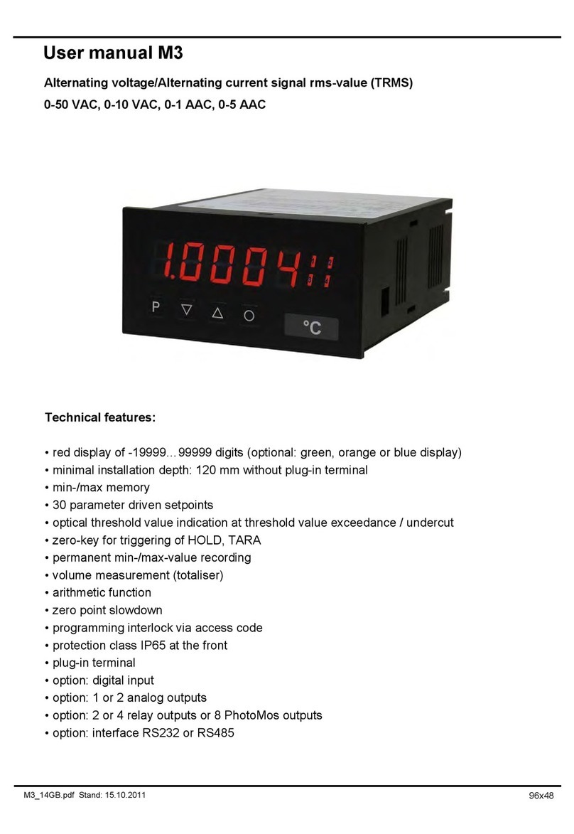
DayTronic M3 User manual

DayTronic
DayTronic 3000PLUS User manual

DayTronic
DayTronic TM3 User manual
